Note: Descriptions are shown in the official language in which they were submitted.
~UAL-STAO.,E TAPEFiE!' LEAF SPFiIN(°., FOR A TRAILEf3
BACKGROUND OF TWE INVENTION
The present invention relates to commercial vehicle suspensions and, more
particularly, to a dual-stage tapered leaf spring for use in a tractor-trailer
suspension assembly.
In general, most trailers, (such as specialty carriers, tankers, dry freight
haulers,
etc.) are equipped with non-driven single, tandem or multi-axle assemblies.
Conventionally, the
suspension systems provided for supporting and damping the relative movement
between each
axle and the trailer frame have included singl~-stage m~lti-leaf springs,
pneumatic spring
systems or a combination thereof. The vast majority of trailers are equipped
with single-stage
multi-leaf springs which are designed to mechanically dampen the trailer when
"loaded" to
n preserve its cargo and provide adequate roll stiffness. Mufti-leaf springs
are a class of leaf
springs having a plurality of three or more constant thickness stepped-length
leafs which are
stacked to fiorm a constant rate, leaf spring assembly. As such, single-stage
mufti-leaf springs
are not designed to differentiate between "loaded" and "unloaded" trailer
operation and thus
normally provide a firm or "stilt" ride .luring loaded operation.
Unfortunately, this "stiff" ride
causes excessive suspension vibration end reduced wheel control during
"unloaded" trailer
operation which detrimentally impacts tho useful service life of the trailer
while causing an
undesirably harsh ride for the vehicle operator:
Conventionally; trailer suspension applicatioris equipped with dual-stage leaf
springs for providing a variable or progressive rate (i.e. "soft" ride when
unloaded and "stilt" ride
when . loaded) have been extremely limited due to the availability of
pneumatic systems.
However, when dual-stags leaf springs have been us~d it is common to employ a
massive and
n-efficient first stage mufti-leaf spring having an additional secpnd stage
leaf mounted thereto.
Traditionally, the first stage mufti-Peaf spring is ized to provide the low
rate "soft" ride when the
g-a ac; a-~,~rr°~
trailer is unloaded (i.e. curb load) with the second stage leaf being
inactive, When the trailer
is loaded (i.e. design load), the second stage leaf becomes actively loaded
for causing the
overall rate to increase so as to produce a firmer ride. According to one
method, a "helper"
spring is mounted above the main spring of the first-stage mufti-leaf spring
and does not
support any load until it engages caroming pads for resisting further
deflection of the multi-
leaf first stage. As such, the change in rate and, in turn, the ride stiffness
is necessarily abrupt
and harsh. Alternatively, dual-stage leaf springs may have one or more
reiatlvely thick second
stages leafs mounted below and adjacent to the shortest leaf of the "first
stage" portion of the
mufti-leaf leaf spring. Upon deflection, rolling contact is made between the
second stage leafs
and the first stage for producing the increased rate. Again however, the rate
transition is
typically abrupt, .
While dual-stage leaf springs have been used in various light-duty truck
applications, such springs have not been used in the heavy-duty trailer
industry, This is
primarily due to the fact that heavy-duty trailer suspensions must be designed
to function for
a significantly larger load-carrying range than is required of modern light-
duty vehicles. As
such, dual-stage multi-leaf springs are heavy and require a significant range
of deflection to
provide the desired rate transition. These design constraints have made
utilization of
conventional multi-leaf dual-stage springs impractical for many trailer
suspension applications.
Modernly, pneumatic suspension systems are being installed in trailers to
provide
means for variably adjusting the rate 6n response to changes in the load
carried by the trailer.
However, pneumatic suspension systems are typically quite expensive and
require additional
structural components for providing sufficient roil and wind-up stiffness in
most commercial
heavy-duty trailer applications.
,~
CA 02059252 2003-10-24
62406-123
SUMMARY OF THE INVENTION
In accordance with the invention, a suspension
system for a trailer having axle means and a chassis frame,
first and second hanger means mounted on each side of said
chassis frame is provided. The suspension system has a
dual-stage tapered leaf spring operably coupled to said axle
means and disposed between said first and second hanger
means for damping the relative movement between said axle
means and said chassis frame, and the dual-stage tapered
leaf spring comprises: a first leaf member having its upper
end surfaces in sliding contact with said first and second
hanger means, said first leaf member having a first tapered
thickness profile; and a second leaf member disposed below
and coupled to said first leaf member such that its upper
end surfaces are adapted to move between positions of
disengagement and engagement with lower end surfaces of said
first leaf member in response to deflection of said dual-
stage tapered leaf spring, said second leaf member having a
second tapered thickness profile; wherein each of said first
and second tapered thickness profiles include a series of
successive linearly tapered increments which each define a
different amount of thickness taper per unit of length
measurement, said linearly tapered increments having
different incremental tapers sequentially arranged and
configured to track a modified parabolic taper profile.
Also according to the invention, a suspension
system for a trailer has axle means and a chassis frame,
first and second hanger means mounted in tandem on each side
of said chassis frame, and a variable rate dual-leaf spring
assembly operably coupled to said axle means and disposed
between said first and second hanger means for damping the
relative movement between said axle means and said chassis
- 3 -
CA 02059252 2003-10-24
62406-123
frame. The variable rate dual-leaf spring assembly
comprises: a first elongated leaf member having a portion
of its upper end surfaces in sliding contact with said first
and second hanger means, said first leaf member having a
first tapered thickness profile; and a second elongate leaf
member disposed below and coupled to said first leaf member
such that a portion of its upper end surfaces are adapted to
move between positions of disengagement and engagement with
lower end surfaces of said first leaf member in response to
deflection of said dual-leaf spring assembly, said second
leaf member having a second tapered thickness profile;
wherein said first and second tapered thickness profiles
include a series of successive linearly tapered increments,
which each define a different amount of thickness taper per
unit of length measurement, said linearly tapered increments
having different incremental tapers sequentially arranged
and configured to approximate a modified parabolic taper
profile, said upper end surfaces of said second leaf member
being normally disengaged from said lower end surfaces of
said first leaf member when said trailer is operating in a
first loaded condition such that engagement of said upper
end surfaces of said first leaf member with said cam surface
means causes said dual-leaf spring assembly to provide a
soft damping characteristic, and wherein said upper end
surfaces of said second leaf member are adapted to engage
said lower end surfaces of said first leaf member when said
trailer is operating in a second loaded condition for
providing a firmer damping characteristic.
Embodiments of the present invention provide a
lightweight dual-stage tapered leaf spring assembly for use
in heavy-duty trailer suspension applications. More
particularly, some embodiments of the present invention are
directed to an improved dual-leaf tapered leaf spring
- 4 -
CA 02059252 2003-1~0-24
62406-123
assembly having a main or first tapered leaf defining a
first stage rate and a second tapered leaf operable to
define a second stage rate. The first and second leafs are
formed to include a tapered thickness profile which closely
approximates a true modified parabolic taper.
Upon installation into the trailer suspension
system, the remote ends of the main leaf operably engage
hanger cams suspended from the trailer frame. The second
leaf is operably mounted below the main leaf and is adapted
to move between positions of non-engagement and engagement
with the main leaf in response to deflection of the leaf
spring assembly. The "approximated" modified parabolic
profiles for each of the main and second leafs are adapted
to provide a smooth non-linear transition between the first
and second stage rates (i.e. between "curb" and "design"
loads) as compared to the excessively abrupt linear
transition associated with conventional dual-stage multi-
leaf springs. More specifically, the smooth non-linear rate
transition is generally parabolic and includes first and
second arcuate transition regions. The first arcuate
transition region is relatively large and occurs upon the
cranked ends of the second tapered leaf engaging and rolling
in on the main leaf upon continued axle displacement for
effectively shortening the second leaf moment arm. The
second arcuate transition region occurs upon continued leaf
spring deflection in response to the main leaf rolling in on
the hanger cams for effectively shortening the main leaf
moment arm. The first and second arcuate regions of the
transition curve are interconnected by a fairly linear load
deflection region which occurs following second leaf
engagement and prior to the shortening of the main leaf. As
such, the cumulative effect of the improved tapered profiles
and unique two-stage camming action is to provide a smooth
- 5 -
CA 02059252 2003-10-24
62406-123
non-linear rate transition between the lower first stage
rate and the higher second stage rate so as to define a
variable rate leaf spring assembly.
In a related embodiment, the main tapered leaf of
the dual-stage dual-leaf spring of the present invention is
designed to have a higher working (i.e. bending) stress
level than the second tapered leaf. In addition, the
working stresses for each of the tapered leafs are uniformly
distributed over their entire length due to the
"approximated" modified parabolic tapered thickness profile
of each of the leafs. As such, the service life and ride
characteristics associated with the lightweight high-stress
tapered leaf spring assembly of the present invention are
superior to conventional non-tapered and linearly tapered
multi-leaf springs while causing uniform stress distribution
in a manner heretobefore only associated with true
parabolical tapered profile. Furthermore, the present
invention is material efficient and designed to maintain
sufficient interleaf clearance for permitting smooth second
leaf to main leaf engagement without causing excessive
interleaf contact or friction upon the full range of axle
deflection. Elimination of interleaf friction lends itself
to substantially lower frictional losses whereby the
available potential energy is substantially increased.
According to a preferred embodiment, the tapered
thickness profile for each of the first and second leafs
incorporates a series of successive linearly tapered
increments which approximate a true modified parabolic taper
profile. More particularly, the successive linearly tapered
increments define a plurality of sequential transition
points which each define a different amount of thickness
taper per unit of length measure for effectively minimizing
- 6 -
CA 02059252 2003-10-24
62406-123
the mass of material used while concurrently achieving
uniform stress levels. As such, the "approximated" modified
parabolic taper effectively replicates a true parabolic
tapered spring in configuration and function so as to
provide maximized spring efficiency at a realistic
production cost.
A further embodiment of the present invention
provides a dual-stage dual-leaf tapered leaf spring that can
be operatively installed in virtually any single, tandem or
multi-axle commercial trailer as an original equipment
suspension component or a retro-fit replacement.
Various other advantages and features of
embodiments of the present invention will become readily
apparent to one skilled in the art upon reading the
following specification taken in conjunction with the
accompanying drawings.
BRIEF DESCRIPTION OF THE DRAWINGS
Figure 1 is a schematic view of an exemplary
commercial tractor-trailer combination having a trailer
supported from tandem axles by front and rear pairs of dual-
stage dual-leaf tapered spring assemblies according to an
embodiment of the present invention;
Figure 2 is a partially broken away side view of
the tandem axle suspension assembly shown in Figure 1;
Figure 3 is an enlarged partially disassembled
view of the rear dual-stage dual-leaf spring assembly of
Figure 2 deflected to its "curb" load first stage operative
position;
- 6a -
i i i
CA 02059252 2003-10-24
62406-123
Figure 4 is a view, similar to Figure 3, showing
the dual-stage dual-leaf spring assembly in an
"intermediate" loaded transition stage position;
Figure 5 is a view, similar to Figure 3,
illustrating the dual-stage dual-leaf spring assembly
deflected to its "design" load second stage operative
position;
Figure 6 is an exemplary comparative graph
illustrating the rate vs deflection characteristics of the
leaf spring assembly shown in Figures 3 through 5 relative
to a conventional multi-leaf single-stage leaf spring;
Figure 7 is a schematic illustration of a modified
parabolic tapered profile and a linear tapered profile;
Figure 8 is a thickness taper profile for a
portion of the main leaf illustrating the plurality of
successive linearly tapered increments which approximate the
modified parabolic taper of Figure 7;
Figure 9 is a view similar to Figure 8
illustrating the thickness taper profile for a portion of
the second leaf;
Figure 10 is an exemplary graphical illustration
of the thickness taper profiles of Figures 8 and 9 as
compared to a conventional linearly tapered leaf spring; and
Figure 11 is a schematic view of a method and
apparatus for forming the "approximated" modified parabolic
tapered thickness profiles according to an embodiment of the
present invention.
- 6b -
i
CA 02059252 2003-10-24
62406-123
DESCRIPTION OF THE PREFERRED EMBODIMENT
In general, the present invention is directed to a
variable or progressive rate leaf spring assembly for use in
tractor-trailer vehicle suspension systems. Furthermore,
the lightweight high-stress tapered leaf spring assembly of
the present invention is readily adapted for installation in
virtually all single, tandem and/or multi-axle trailer
suspension systems for supporting and damping relative
movement between the trailer frame and each of the axles.
According to a preferred embodiment of the present
invention, a dual-stage dual-leaf spring assembly is
disclosed which incorporates a tapered thickness profile
adapted to approximate a "modified parabolic" taper. As
will be appreciated, the primary functional
- 6c -
CA 02059252 2003-03-05
62406-123
charact~:;slia-of trailer suspension systems aaocee de~sd by the.'rate' and
'static deflection' of
the leaf spring. The rate is the leaf spring's #a~nge in load per unit of
deflection (ibs/'u~ch)..
Static deflection (inches) is derived by divicfang tl~e rate at a static load
position by the static
load for determining the 'stiitness" of the suspertsiOrt and the ride
frequency of the vehicle.
A "soft' ride ~equtres a relaUveiy large static deflec~on of the vehicle's
suspension system while
a "firm' ride.generaily requires a smaller of static deflection: tt is to be
understood that
the tapered dual-leaf spring assembly of ttte present invention Is primarily
adapted for
Incorporation into heavy-duly trailer suspon. application which operate within
a large
- variation in load carrying capacity to provide desireade ride and load
handling characteristics
under the entire range of loaded conditions.
wih particular reference now to Figure t , an exemplary tractor-Iraiier
combination
t 0 is shown. More particularly, tractor 12 is operatively coupled to trailer
14 in a known
manner for transporting a cargo (i.e. gas, bu~hg , machinery, cement, etc.).
Tractor
trailer 10 is exemplary in nature and is merely inler~ded to illustrate one
type of heavy-duty
commercial transport vehicle to which the present iwrenik~n is directed.
Trailer 14 is shown to be of the axis type, that is, the end of trailer 14
remote from tractor cab 12 is supported by one a more sets of front and rear
wheels 16 and
18, respectively, which are rotatably mourned to irons and rear axles 20 and
22, respectively,
arranged one behind. the other in a tandem rte.. A mechanical suspension
system 24
. is provided for damping relative movement been trailer 14 and axles 20 and
22. For
purposes of clarity, F"~guce 1 shows tracer 14 w~h its driver side suspension
and wheels
removed for providing a better view of mect~i suspension system 24. As wiU be
detailed hereinafter, the present invention is directed to a
unique dual-leaf tapered leaf spring assembly which is .
adapted for use with virtually any ~:onventional trailer
suspension system or axle
~~ ~' :~. ~ 3~d
arrangement ofi the type incorporating multi-leaf spring assemblies.
Suspension system 24 is
shown to include a pair of firont leafi springs 26A (one on each side of
trailer 14) and a pair
of rear leaf springs 26B (one afi each side of trailer 14) aligned in tandem
relationship.
Preferably, front and rear springs 26A and 268, respectively, are substantial
identical in
configuration and operational characteristics. In general, front and rear
pairs of leaf springs
26A and 26B, respectively, are adapted to be operably mounted between firame
stringers 30
(frame stringers 30 are located on both sides of trailer 14) and their
respective front and rear
axles 20 and 22 for supporting and damping the relative movement therebetween.
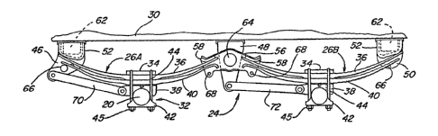
With particularly reference to Figure 2, leaf springs 26A and 26B are shown as
being connected at their rnid-points to (rant and rear axlos 20 and 22 in an
"oversiung" mannor
using conventional clamping means 32. More specifically, the connections are
preferably
identical for both front and rear springs 26A and 268, respectively, with
clamping means 32
comprised of a top clamp member 34 confiigured to embrace an inactive portion
ofi the upper
"tension°' surface of main leaf 36 for leaf springs 26A and 268. An
upper face of a lower axle
seat 38 engages a generally flat inactive portion of the lower "compression"
surface 39 of a
second Isaf 40. The lower face ofi lower axle seat 38 is shaped complimentary
to and
ertgageable with its respective axle. Similarly, a lower saddle clamp 42 is
disposed below and
matingly engages its respective axle. U-bolts 44 and torque nuts 45 are
adapted to securely
mount front and rear axles 20 and 22, respectively; to front and rear pairs of
leaf springs 26A
and 268, respectively, in a known matter such that any movement of the axles
causes a
corresponding deflection or movement of leaf springs 26.
Each front leaf spring 26A is supported between a front hanger bracket 46 and
a center hanger bracket 4e3 which are both maunted to frame stringers 30.
Likewise, each rear
leaf spfiing 26B is supported between central hanger bracket 48 and a rear
hanger bracket 50.
g _
CA 02059252 2003-03-05
62406-123
Front and rear hanger brackets 46 and 50, respeciveiy, include bearing or cam
pads 52
against which the outer non-adjacent ends of main leaf 36 for each of front
and rear leaf
springs 26A and 268, respectively, ate adapted to engage. As such, front
hanger brackets 46
and rear hanger brackets 50 are secured to the trailer's chassis frame
stringers 30 at locations
corresponding to the remote ends of Leaf springs 26; An equalizer member 56 is
supported
within center hanger bracket 48 and indudes a pair of simifariy angled bearing
pads 58 which
are adapted for normal engagement with the inner adjacent ends of front and
rear pairs of leaf
springs 26A and 268, respectively. Front, center and rear hanger brackets 48,
48 and 50,
respectively, are generally inverted U-shaped structural members having
downwardly extending
side plates between which the respective leaf springs 26 and equalizer member
56 are
disposed. Furthermore, front and rear hanger brackets 46 and 50, respeciiveiy,
are provided
on opposite sides of trailer 14 and are fixedly interconnected via cross-
support tubes 62 for
providing structural rigidity. likewise, each equalizer member 56 is mounted
inside Its central
hanger bracket 48 behnreen its respective side plates and are Tucediy
interconnected via a cross-
support tube 64 extending transversely between frame stringers 30. In
addition, retainer cubes
66 and 68 extend transversely between the side plates of front and rear hanger
brackets 46
and 50, respectively, and equalizer member 56 to inhibit dislocation of front
and rear leaf
springs 26A and 266, respectively, and which ars located beneath the ends of
second teat
40.
As nosed above, and as is standard in most tandem axle suspensions, the non-
uniform loading on the inner adjacent ends of irorri and rear leaf springs 26A
and 268 are
equalized via equalizer 56. A front torque rod 67 is connected between the
side plates of
iront.hanger bracket 46 and axle seat 38 of i~ont leaf springs 26A while a
second torque cube
69 is interconnected between the side plates of c~er hanger bracket 48 and
spring seat 38
- 9 -
f
~~~~~~~4~: ~
of rear leaf springs 26B, As previously noted, while the leaf springs 26 of
the present invention
is shown in a tandem axle arrangement it will be appreciated that leaf springs
26 can be
installed in other suitable mechanical suspension systems and axle
arrangements.
With particular reference now to Figure 3, one of rear leaf springs 26B is
shown
in greater detail with several of the center clamping components removed for
additional clarity.
Since front leaf springs 26A are substantially identical to rear leaf spring
26B, the following
description is likewise applicable thereto. As is apparent, leaf spring 26B
includes first or main
tapered leaf 36 having its opposite terminal end portions of its upper
"tension" surface 69 in
engagement with angled cam surface 70 of cam pad 52 and bearing pad 58 at
positions
outwardly of "roll-in" centerlines 72 and 74, respectively. As such, the
effective "active" length
of main leaf 36 is at lts greatest length when trailer 14 is at its "curb"
loaded capacity.
Moreover, in the position shown, leaf spring~26B is deflected to the first
stage "curb°' loaded
(i,e. trailer ~ 4 is substantially unloaded) position. At "curb", it is
desirable to have a relatively
low rate for a "soft" ride characteristic when trailer 14 is being transported
in its substantially
"unloaded" condition. As such, the limited engagement of main leaf 36 with
surface 70 of cam
pad 52 and bearing pad 58 defines a '°first stage'° rate with
ends 80 of second leaf 40 spaced
below and disengaged therefrom. Each end 80 of second leaf 40 is cranked or
slightly
downturned to. define a roll-in "contact" area specifically designed to engage
the underside
"compression" surface 82 of main leaf 36~upon continued axle deflection. In
addition, one
cranked end 80 of second leaf 40 terminates in a down-turned hook 83. The
cranked ends
80 are adapted to maintain a relatively constant interleaf gap opening 84
spanning between
the "inactive" central clamped portion of the leafs and the contact area of
cranked ends a0.
l~s will be described hereinafter in greater detail, each of first and second
leafs 36 and 40,
respectively, is formed to include a tapered thickness profile which
effectively "approximates"
- Zp
CA 02059252 2003-03-05
02406-123
true modified parabolic surface arad Lnsures maintenance of
:interleaf gap 84. F~rthe:r~noz~e, :i_ruter.ro41 ~~ap 84 provides the
clearance necessary to promote smooth sec;and leaf 40 to main
:Leaf 36 engagement and ro:L:L-rn withcmt_ geruerating excessive
interleaf contact or friction. As sucr~, ~::.he present
invention lends itself t:o low friction losses for keeping
1=he potential energy (i.e. a~Tai.l.ab:Le d<~mp:i.r:g) within the
desired range of loaded and m.loaded conda.tions.
Following the tapexving operation to be described,
each of first and second leafs 36 arid 40, respectively, are
cambered to produce the gerlex:al:L.~r serni~-e:L.l iptical curvature
shown from utilization c>f conventional hot_ forming and
quenching processes . A~; noted, each of f:_rst and aeco.nd
7_eafs 36 and 40, respecr.ivE~l~, has an "i.nacti.ve" central
clamped area of a predetermined length haring spacers 86
disposed t=herebetween. A ceruter bolt E~8 ~.oasses through
center bolt holes 90 punched i.n each leaf and a lock nut 92
is torqued thereon to rigidly clamp leafs 3o and 40 as dual-
l.eaf spring assembly 26h.
With referencEnow to figures 4 and 5, various
deflected positions of leaf spring 26B are shown. While
these Figl.zres are similar t:o Figure 3, the-y arc= intended t.o
i.llustratE: the "camming" action of bot:rn leafs upon continued
axle displacement. In particular, as the load on trai:Ler 14
i.s increa:>ed past the "c:urb" Lo,:~d. level, rc~ain. leaf 36 :Ls
sufficiently deflected untz.l it s underside "compression"
~~urface 82 contacts the corntact areas of t:he second leaf
spring 40 on the outer most: cranked entportions 80 on its
tension surface 94 to initiate the rate transition from the
lower first stage rate to a hig~ner second stage rate ride
characteristic. In effc>.ct, instread cof an abrupt and harsh
11
CA 02059252 2003-03-05
~~2406-123
.Linear load transition point as i.s typ:ical.l.y associated with
conventional dual-stage mufti -leaf spzr:a.ng:~, the present
invention provides for a smooth non-linear transition which
is generally parabolic in nature. More particularly, crank
ends 80 of second leaf 40 are adapted too "roll-in" from the
"curb" position shown i;i Figt.~re :3 to t~xae .nitial contact
position shown in Figure 4 with respect t~~> centerlines 72
and 74 upon continued
11. <:~
~' ~. ~', f."," ~g'~:~ k~..rJ,
~4c v. ......o '-.,. ~:a . .~
suspension deflection to provide a relatively long initial parabolic
transition segment 100 (see
Figure 6). This sliding or rolling action effectively shortens the "active"
length or moment arm
of second leaf 40. However, upon continued deflection of leaf spring 268, the
loading thereon
approaches the "design load" level, wherein tension surface 69 of main leaf 36
begins to "roll-
s in" on surface 70 of hanger cams 52 and 58 for effectively shortening the
"active" length thereof
so as to create a second parabolic transition portion 102 (Figure 6). As best
seen in Figure
5, at "design load" both main leaf 36 and second leaf 40 havo effectively
rolled in relative to
centerlines 72 and 74. In fact, the tapered profiles of each leaf and the
change in effective
length act to produce a variable rate as shown at 104 in Figure 6. The various
rate transition
regions are best seen from the exemplary rate vs deflection curve of Figure 6
which shows the
smooth and relatively long cumulative transition curve i06 of leaf spring 26B
compared to 'the
constant rate curve 108 for a conventional single-stage multi-leaf spring.
With particular reference now to Figures 7 through 10, the principles embodied
within the "approximated" modified parabolic tapered thickness profiles of
first and second leafs
36 and 40, respectively, will now be described in greater detail. In general,
it is known that
tapered leaf springs provides superior volumetric material efficiency as
compared to a
conventional constant thickness multi-leaf spring assembly designed to provide
similar
operational characteristics. This volumetric efficiency defines the amount of
potential energy
which leaf spring 26B is capable of storing at a specified stress level
relative to its volume of
"active" material. Therefore, it is desireable to utilise a tapered leaf
springs since they are more
efficient and have a relatively constant stress distribution from its line of
encasement (starting
taper point 1 i 0 at end of the "clamped" area) to its paint of load
application.
With reference to Figure 7, a schematic comparison is shown between a single
linearly tapered thickness profile 112 and a true modified parabolic tapered
profile 114 are
-~ 22
i~"'. f ;' :~ fiT ~' ~,A
8 ~. .e~~.xa.,s
shown. Each thickness profile begins tapering at point 110 from a starting
thickness "t;' and
terminates at a predetermined end thickness "t;'. Tap~r profile 314 is
referred to as "modified"
sinee s "true" parr~bolle tsp~r d~cr~ss~s In thlckn~ss to zero ihlckn~ss at
the point of loading
such that "t;' would equal zero. As such, a modified parabolic taper includes
an end portion
of a known thickness "t~' for facilitating load application. Howover, a
modified parabolic taper
is an impractical design based on prohibitive production costs and
manufacturing constraints.
Therefore, the present invention is directed at utilization of a tapered
thickness profile which
"approximates" a modified parabolic taper far maximum material efficiency at a
realistic
production cost. This profile is shown schematically at 11 & in Figure 7.
Moreover, exemplary
approximated modified parabolic taper profiles of the type utilized in both of
first and second
leafs 36 and 40, respectively, are shown in Figure 8 and 9 which substantially
replicate the true
parabolic profile shown in Figure 7.
More particularly, as can best be seen from Figures 8 and 9, the tapered
profiles
of first and second leafs 36 and 40, respectively, approximate or "track" a
modified parabolic
taper by incorparating a successive plurality of linearly tapered increments
having distinct and
different transition points. More particularly, according to the embodiment
shown there are five
transition points T1 through T5 for each leaf having an predetermined change
in taper finch
per inch) which are specifically selected to minimize the material volume and
achieve a higher
and more uniform stress distribution throughout,the entire leaf length. The
initial quick taper
20. (T, to T2) allows the working stress from each leaf to be transferred more
uniformly to inhibit
premature stress-related failure in the center clamp area.
For purpose of example only, Tables t through 4 list transitional taper
Information
and point thickness Information for leaf members 36 and 40 for leaf spring
268. As will be
appreciated, the specific modified parabolic taper profile for second leaf 40
is independent of
_ ~3 _
CA 02059252 2003-03-05
62406-123
and' different than the modified paraboic taper profile for first main leaf
36. This is done to
provide a higher working stress level ~ main leaf 96.
With reference to Figure ~ Table 1 provides the incremental tapers for one-
half
vt main leaf 36 (the other had being ider~al~.
t~ 1
TRANSDRTA - AA~IN ~,~=AF
TRANSITION INCi~tENTAL TAf'EH
1 o POINTS II~Cl~i1
T, TO T~ .314
T: TO T, .037
T, TO T, .047
T, TO TS .043
t 5 Similarly, Table 2 provides the incremental tapers for one-half of second
leaf 40 shown in
Figure 9.
T 2
THANSIf~t~l O~A,T~A - SECOI~!!'~l_~AF
20 TRANSITION iNCi~IENTAL TAPER
POINTS i
T, TO T~
T, TO T3 , 039 . .
'i', TO T, .045
25 T, TO Ts .053
- 1~1 -
CA 02059252 2003-03-05
62406-123
With reference now to Tables 3 and 4, the taper information for various
comparison curves of Figure 10 are d~closed. More specifically, curve 120
represents the
modified parabolic taper profile of main teat 3& c~u a 122 represents a
constant linear taper
profllo comparison; curve 124 represents the rno~d parabolic taper prollle of
second teal 40;
and curve 126 designates its corresponding at'rve constant linear taper. As is
apparent,
curves 120 and 124 closely 'track' the true mod~ad taper shown in Figure 7.
The difference
inforinatlon listed in Tables 3 and 4, atxi repr~eaa~d in plots 128 and 130 of
Figure 10, show
the substantial impact the modItisd taper protila ~ on material utilization
and working stresses .
relative to a constant linear taper.
TA 3
TAPER Ct7MPARISON - MAIN i.EAF 1361
REFERENCE ~~APPROXIMATBD~' LINEAR LINEAR
POINT PARABOLIC TAPER TAPER DIFFERENCE
(INCHES) (INCHES) (INCHES)
A 1.300 (~ 1.300 0.000
g - 1.300 1.300 0.000
C 1.262 1.264 -0.002
p 0.948 0,964 -0.016
0.875 . 0.890 -0.015
F 0.837 0.849 -0.012
G 0.800 0.808 -0.008
0.762 0.767 -0.005
1 0.725 0,726 -0.001
0.678 fkti85 -0.007
K 0.632 0.644 -0.012
t" 0.585 0.603 -0.018
0.543 0.562 -0.019
N 0.500 (t3 0521 -0.021
p 0.500 , ~ 0.500 0.Q00 . .
P ~ ~ 0.500 ~ 0.500 0.000
- l5 -
CA 02059252 2003-03-05
62406-123
w According to the preferred method, constant thickness bar stock 210 is
heated
to a predetermined elevated temperature and is located between cam proiiie
dies 206.
Carriage 204 is then moved into a position suph that roil 202 die may be
lowered into
engagement wish a generally Dear roll start sixfaaa 214 of cam profile dies
206. Preferably,
roll 202 Is rotatabiy driven concurrently with the horizontal movement of
carriage 204 to cause
roll 202 to follow the contour of cam dte 206. Its such, .a majority of the
material flow is in a
lengthwise direcilon. The number of 'passes" a rol~ng operations required for
roll 202 to
completely follow the entire carn die surface 212 is dependent on the severity
and length of
the taper desired. Thereafter, the second half of bar stock 27 0 is tapered
(rolled 'in a similar
manner.. Following the tapering operation, .the tapered leafs 36 and 40 are
reheated, hot
formed and then quenched to the desired semi-el~cai curvature, The hot forming
operations
are adapted to provide ranked ends 80 and hook 83 on second leaf ac.
The foregoing discussion discloses and describes an exemplary embodiment of
the present invention. One skilled in the art win readily recognize horn such
discussion; and
from the accompanying drawings and claims, that ~rerious changes,
modifications and variations.
can be made therein without departing from the spirit and scope of the
invention as defined
in the following deans.
- m .-
CA 02059252 2003-03-05
62406-123
TABLE 4'
~r~
TAPER COMPARtSO~I w SIi,CONp LEAF !40)
REFERENCE "APPROXIMATED" LINEAR ~ LINEAR
'POINT PARABOLIC TAPER TAPER DIFFERENCE
(INCHES) (INCHES) CINCHES)
. ... -1.300 (t~ 1.300 D.000
g 1.300 1.300 0.000
C 1.2?4 ~ 1.277 -0.003
1.053 1.081 -0.028
E 0.991 1.017 -0.026
F 0.952 Q972 -0.020
G, 0.913 0.927 -0.014
~
. H ~ ~ 0.874 ~ ' 0.882 -0.008
I . ~ 0:835 Q837 -0.002
~ ,y ' 0.789 0.792 -0.003
5
0.744 0.747 -0.003
0.698 0.702 -0.004
0.646 0.657 -0.011
0.593 0.612 -0.019
2p O 0,540 0.567 -0.027
P 0.500 (t,~ 0.522 -0.022
p 0.500 0.504 0.000
Wish reference nowi to Figure 11, a method and apparatus for forming the
~appro~mated' modified paratw~c taper for the ikst and second feats 36 and 40,
respectively,
25 is schematically shown. In general, a caper rolling apparatus 200 includes
a vertically movable
roll 202 and a horizontally movable carriage 204. Left and right cam dies 206
(one shown) are-
securely affixed to a top surface 208 of carriage 204 in a predetermined
spaced relationship
adapted to permft ons or mae pieces of constant tf~daaess bar stock 2i0 to be
disposed
therebefinreen. Cam dies 206 are cart to include a rammed rolling surface 212
which
30 corresponds to the desired approximated modified parabolic taper. In
addition, cam profile
dies 206 are designed to compensate for thermal shdNCage of bar stock 210
following the hot
tapor rolling process.
_ 1~ _