Note: Descriptions are shown in the official language in which they were submitted.
VO90/16010 2 Q ~ ~ ~ 7 Q PCT/US90/03501
IMPROV~ TS TN OR ~FT-~TING TO ~-RAY C~S~TTF.S
1. BACKGROUND OF T~E INVENTION
This invention relates to x-ray cassettes
intended for shielding sheet film from visible
radiation and holding the film flat and in intimate
contact with intensifying screens during exposure of
the film to x-rays.
2. DESCRIPTION RELATIVE TO THE PRIOR ART
X-ray cassettes are known which comprise two
rectangular panels which are connected by a hinge at
one edge which allows the panels to be opened for the
introduction of a sheet of film and closed for
holding the film. The loading and unloading of the
film is done in the dark and one of the purposes of
15 the cassette is to shield the film from visible
radiation until the cassette is returned to the dark
and unloaded so that the film may be processed.
Thus, while it is, of course, easy to make the panels
of the cassette opaque to visible radiation but
20 transparent to at least some degree to x-radiation,
attention must be given to sealing the peripheries of
the panels against the intrusion of visible
radiation. Another important role of the cassette is
to maintain a complete intimate contact of
intensifier screens with the sheet film when the
cassette is closed. Those skilled in the art know
that where an intensifier screen is spaced from the
film, the image created in the film is blurred
because light from a point on the screen spreads to
30 an area on the film whereas with intimate contact the
point source on the screen is imaged as a point on
the film. For the purpose of gaining overall
intimate contact, it is known to include resilient
foam pads between a panel and its associated screen.
35 The prior art shows that even the use of foam pads
has not proved adequate for gaining the necessary
-
~R
20S927~0O90/16010 PCT/US90/0350]
--2--
overall intimate contact. U.S. Patent Specification
no. 3,504,180 describes an x-ray film cassette in
which the two panels are cylindrically curved, in the
open condition of theicassette, with the a~es of the
cylinders being parallel to the hinge connecting the
panels and with the panels being convex towards one
another. The panels are formed of sheet aluminum and
have light seals around their three edges other than
the hinge edges. The hinge forms a light seal along
the fourth edge.
While the cassette described in the
aforementioned Patent Specification has been very
successful commercially, the drive to reduce the
dosage of x-rays to which a patient is subjected
during the taking of an image, has lead to the
introduction of materials for cassette panels with
even greater transparency to x-radiation than
aluminum. Carbon fiber reinforced plastics material,
especially epoxy resin, has found commercial
acceptance as a substitute for aluminum in the
manufacture of at least that panel which is to be
directed towards the source of x-rays. It has been
found that dosage may be reduced by as much as 80%
when such a panel, rather than an aluminum panel, is
used. However, a fiber reinforced plastics panel has
a disadvantage when compared to an aluminum panel in
that once it has been molded or cast, its shape
cannot be modified. Even with the cylindrical
aluminum panels, it has been found necessary to
conduct an inspection of the integrity of the light
seal around the periphery of the cassette. If at
some location a lack of integrity was found, it has
been practice to deform the panel or panels so that
integrity is gained. Because the aluminum is
ductile, the applied deformation is permanent. The
fiber reinforced plastics panels are not susceptible
20~9X7QO90/16010 PCT/USgO/03501
--3--
to such a f inishing operation to gain seal integrity,
because they are not ductile. Tests of panels of
both materials involving creation of images, show
that there is room for improvement in gaining overall
contact of the screens with the film. Failure to
create a good light seal at the edges and failure to
gain overall contact of the screens with the film are
both derived from failure to create a panel which is
planar and parallel to the other panel in the closed
condition. It has been found that cassettes wherein
one or both panels are formed of plastics material
and have the cylindrical shape described in the
aforementioned U.S. Patent Specification, there may
be failure to gain the planarity and parallelism of
lS the panels in the closed condition and this may
appear as failure in the integrity of the light seal
and/or failure to gain overall contact of the screens
with the film and, because of the inability to deform
a plastics panel in a finishing operation, such
cassettes are useless.
It is an object of the present invention to
overcome the light seal and overall screen contact
problems in x-ray cassettes in which at least one
panel is formed of plastics material,
j~ 5 SU~ARY OF THE lNV~;NllON
The present invention solves the problem of
the prior art by forming the plastics panel so that
it not only exhibits the cylindrical form about an
axis parallel to the hinge line and convex towards
the other panel, but also is curved out of the
cylindrical towards the other panel so that it has
regions which exhibit some concavity towards the
second panel. In mathematical terms this may be
expressed as the panel having negative gaussian
curvature. Such regions curved towards the other
panel serve to ensure integrity of the light seal and
continuity of contact of the screen with the film.
WO90/16010 2 0 5 9 27 ~ PCT~US90/03501
BRIEF DESCRIPTION OF T~E DRAWINGS
An embodiment of the present invention will
now be described, by way of example, with reference
to the accompanying drawi-ngs, in which:
Fig. l is a diagrammatic representation of a
cassette, in accordance with the present invention,
in an open condition;
Fig. 2 is a scrap cross-section of marginal
portions of the panels of the cassette illustrated in
Fig. l, in a slightly opened condition, showing the
edge light seal;
Fig. 3 is a plan view of the cassette
illustrated in Fig. l, with the panels in a fully
open condition;
Fig. 4 is a scrap cross-section of the hinge
connecting the two panels of the cassette illustrated
in Fig. l, with the panels in the fully open
condition;
Fig. 5 is a scrap cross-sectional view of
the margins of the panels opposite the hinge, of the
cassette illustrated in Fig. l, with the panels in
the fully closed condition, illustrating reinforcing
and light-sealing strips secured to the margins of
the panels, and also illustrating intensifying
screens and foam pressure pads and a film sheet;
Fig. 6 is a plan view of half a panel in
accordance with the prior art, which panel is
cylindrically curved, with contour lines drawn
thereon to indicate the shape of the panel; and
Fig. 7 is a view similar to that of Fig. 6
but illustrating a half of a panel in accordance with
the present invention, again with contour lines drawn
thereon.
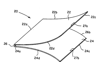
Fig. l of the accompanying drawings
diagrammatically represents an X-ray cassette 20 in
accordance with the present invention and in the open
2059270
~O90/16010
PCr/US90/03501
--5--
condition appropriate for the loading and unloading
of a sheet of film (not shown in Fig. 1). The
cassette 20 includes a first panel 22 and a second
panel 24. The two panels 22 and 24 are generally
rectangular and measure somewhat larger than 14
inches by 17 inches, which is the size of film which
the presently described embodiment is intended to
accommodate. The first panel 22 has long edges 22a
and 22c and short edges 22b and 22d. The second
panel 24 has long edges 24a and 24c and short edges
24b and 24d.
The panels 22 and 24 are connected by a
hinge 26 at the edges 22a and 24a of the panels 22
and 24, respectively. The form of the hinge 26 will
be described in detail subsequently herein. The
hinge 26 allows the panels to be moved from an open
position, as illustrated in Fig. 1, to a closed
condition, and vice versa. Latch means 27a, 27b are
provided at the middles of the edges 22c and 24c of
the panels 22 and 24, respectively. The latch means
27a and 27b serve to releaseably retain the panels 22
and 24 in the closed condition.
The edges 22b, 24b, 22d and 24d are provided
with labyrinthine light seals 28, not illustrated in
the diagrammatic representation which is Fig. 1, but
which are shown in section in Fig. 2. The light
seals 28 consist of a first part 28a on the first
panel 22 and a second part 28b on the second panel
24. The seal parts 28a and 28b have outboard
shoulder surfaces 30a and 30b, respectively, which
bear against one another in the closed condition.
Inboard from the shoulder surface 30a, the seal part
28a has two continuous ribs 32 and 34 which project
towards the other seal part 28b. The other seal part
28b has a channel 36 adapted to receive the rib 32.
The rib 34 of the first seal part 28a nests at the
205~270O90/16010 PCT/US90/03501
--6--
inboard edge of the seal part 28b in the closed
condition. In Fig. 2 the seal parts are spaced and
they approach and depart from one another for full
closing and further opening by relative movement in
the directions of the arrows 38. The seal parts 28a
and 28b are formed on the margins of the panels 22,
24 by insert molding and, hence, ar~e bonded to the
panels. The seal parts 28a and 28b are formed of
black opaque resilient plastics-~material.
The insert molding step which forms the edge
seal parts 28a and Z8b also forms the hinge 26.
Reference is now made to Fig. 3 of the accompanying
drawings. For the insert molding step, the two
panels 22 and 24 are held generally coplanar with the
edges 22a and 24a adjacent but spaced from one
another. The two seal parts 28a, the two edge seal
parts 28b and the hinge are formed, by insert
molding, as an integral H-shaped whole. It will be
observed that the edge seal parts 28a extend around
the two corners of the panel 22 remote from the hinge
26, onto the side 22c, for a short distance, as
indicated at 40. Similarly the edge seal parts 28b
extend around the two corners of the panel 24 remote
from the hinge 26, by a short distance, as indicated
at 42.
The form of the hinge 26 is illustrated in
cross-section in Fig. 4. In essence, the hinge is a
bridge 44 between continuations 46 and 48 of the seal
parts 28a and 28b, respectively, along the edges 22a
and 24a, respectively. The bridge is waisted at its
two ends, as shown at 50 and 52, and it is at these
waists that hinging occurs. The bridge 44 is
continuous along the edges 22a and 22b and hence acts
as a light seal when the panels 22 and 24 are in the
closed condition. ~owever, the continuations 46 and
48 of the seal parts 28a and 28b are provided in case
a rupture should develop, after extensive use, in the
waists 50 and 52.
2059270
WO90/16010 PCT/US90/03501
Light sealing at the edges 22c and 24c, when
the panels are in the closed condition, is provided
as illustrated in Fig. 5. The first panel 22 has
~ecured to it by rivets 54 an L-section strip 56
which extends substantially the full length of the
edge 22c, to be contiguous at its ends with the
continuations 40 of the edge seal parts 28a onto the
edge 22c, A continuous labyrinthine light seal
element 58, formed of black anodized aluminum, is
secured to the inner surface of the panel 22, also by
the rivets 54.
The qecond panel 24 has secured to it by
rivets 60, an L-section strip 62 which extends
substantially the full length of the edge 24c, to be
contiguous, at its ends, with the extensions 42 of
the edge seal parts 28b onto the edge 24c. A
continuous black anodized aluminum labyrinthine light
seal element 64, complementary to the element 58 on
the panel 22, is adhered to the inner surface of the
panel 24.
The L-section strips 56 and 62 are formed of
stainless steel and while they have stiffness they
are not infinitely rigid. Not only do they serve as
light seals, but also they serve as stiffeners, it
being recognized that the latch means 27a, 27b are
disposed at the middles of the edges 22c and 24c and
are of short length relative to the edges 22c, 24c.
Those skilled in the art know that a single latch has
an advantage in that with two latches it is possible
for the condition to occur in which one is latched
and causes a casual observer to think that the
cassette is properly closed and to assume that the
light seal has good integrity. However, in truth,
only one latch is latched and in the region of the
other latch the seal integrity is bad and the film is
fogged. Thus, the single latch has the advantage in
2~5~27~
WO90/16010 PCT/US90/03501
that the cassette i8 either properly latched closed
or it is not latched at all and a person loading the
cassette in a darkroom cannot be fooled. However,
because there is only a single latch and it is of
short length , there are places at the side of the
cassette remote from the hinge, which are not
retained together by a latch and hence, in such
places the panels tend to be forced away from one
another by the reaction presæure of the foam pads.
The L-section strips are provided along the edges of
the panels remote from the hinge to strengthen them
and resist the divergence of the panels.
In Fig. 5 there is also illustrated
diagrammatically, a film sheet 66 sandwiched between
intensifier sheets 68 and 70. Between each
intensifier sheet 68 or 70 and its associated panel
22 or 24, there is, in known fashion, a pressure pad
72. Each pressure pad 72 is in the form of a sheet
of foamed resilient plastics material and serves to
ensure intimate contact of the intensifier sheet 68
or 70, respectively, with the film sheet 66 when the
cassette is in the closed condition.
The second panel 24 i8 of known form and
consists of aluminum sheet. It is of generally
cylindrical shape with the axis of the general
cylindrical form being parallel to the hinge 26 and
with the convexity of the generally cylindrical form
facing the first panel 22. Fig. 6 is a plan view of
half of the second panel 24 as seen from the concave
side. The half which is represented in Fig. 6 is to
the side of a line perpendicular to the axis of the
hinge 26 and passing through points at the centers of
the edges 24a and 24c. The panel 24 is symmetrical
about that line. Drawn on the panel half are contour
lines 76 representing the depth of the panel below a
plane including the edges 24a and 24c. It will be
2059270
W090/16010 PCT/US90/03501
recognized from the fact that the contour lines are
all rectilinear that the panel 24 is cylindrical.
The representation of the contours in Fig. 6 is
appropriate for the panel in an open condition and
before it has edge seals 28, the hinge 26 and the
strip 62 and light seal element 64 associated with
it.
The first panel 22 is formed of carbon
reinforced plastics material which, for example, may
be an epoxy or a polyetherimide. As is known, such
panels have about one fifth the opacity to X-rays
when compared to aluminum panels of similar
mechanical strength.
Fig. 7 is a plan view, similar to that of
Fig. 6, but showing a half of the first panel 22. In
Fig. 7 also, only half the panel is illustrated, and
again it is a half to the side of a line 79
perpendicular to the hinge and passing through the
middles of the sides 24a and 24c. The panel is
symmetrical about that line because, in the present
embodiment , the latch means 27a and 27b are located
at the middles of the sides 22c and 24c,
respectively, of the panels 22 and 24, respectively.
In Fig.7 also, contour lines 80 are drawn on the
outline of the half panel. Again, the contours are
appropriate for the panel 22 before the application
of edge seal parts 28a, hinge 26 and strip 56 and
sealing element 58. It will be observed that the
first contour line immediately adjacent the edge 22a,
which is the edge at which the hinge will be formed,
is substantially rectilinear and parallel to the edge
22a. Thus, immediately adjacent the edge 22a the
curvature of the panel 22 is substantially
cylindrical. It will also be observed that the
further from the edge 22a towards the middle of the
panel, so the contour lines 80 bend more adjacent
205927~
WO90/16010 PCT/US90/03501
--10--
the edge 22b. It will be seen that adjacent the
center line 79 the, contour lines are substantially
rectilinear and-parallel which indicates that along
the center line 79 the curvature of the panel is
substantially purely cylindrical. That cylindrical
form is, of course, concave to the viewer of Fig. 7,
that is, the cylindrical curvature is convex to the
other panel 22. The curved form of the contour lines
80 as they approach the side 22b, with the contour
lines being closer to one another at the edge 22b
than at the center line 79, with a bigger space
between the two 0.365 contour lines at the edge 22b
than at the center line 79, indicates that there is
convexity of the panel, towards the viewer of Fig. 7,
superimposed on the overall concavity resulting from
the cylindrical curvature of the panel. In other
words, the surface of the panel drops away from a
line perpendicular to the center line 79 and parallel
to the surface of the panel at the center line 79,
progressively as the distance from the center line
increases. Thus, it may be said that the first panel
has regions which depart from the cylindrical and are
curved out of the cylindrical towards the other,
second panel, the said regions exhibiting some
concavity towards the second panel. It may also be
said that the panel exhibits negative gaussian
curvature, with a few areas of positive, when the
panel is in a cassette and in the open condition
The shape of the panel 22, which is
represented by the contour lines in Fig. 7, was
arrived at by computer modeling techniques. In
essence, it was assumed that two panels of similar
material and cylindrical curvature and hinged at one
edge, were closed on one another and held together by
a latch at the middle of the edges opposite the hinge
edge. The computer was used to show where there
~59270
WO90/16010 PCT/US90/03~01
would be deviation of the panels from the planar and
parallel condition, and the magnitude of such
deviation. Such deviation would, of course, in real
life, translate into gaps between the shoulders 30a
and 30b of the light seals and, possibly, lack of
contact of the screens with the film. The computer
was then caused to, in the model, deform each panel
by a dimension equal to the dimension of the
deviation, at each point on the facing surfaces of
the panels. An iterative process was instituted,
with the computer again closing the panels, in the
model, and again measuring the deviations. It was
found that only two such iterations were needed to
arrive at a shape for the panels which resulted in
good light sealing and screen contact. In this
computer modeling technique, the effects of the
pressure pads 72, 74 which, being compressed when the
cassette is closed, exert pressures on the panels
tending to deform the panels at locations other than
immediately adjacent the hinge and the latch, was
also taken into account. Also taken into account
were the effects of the strips 56 and 62, the light
sealing elements 58 and 64 and the light seals 28.
As stated above, the computer modeling
procedure assumed two identical panels. In the
embodiment particularly described above, one panel is
formed of fiber reinforced plastics material and the
other is formed of aluminum. The use of different
materials for the panels is because the
fiber-reinforced plastics material is many times more
expensive than aluminum and, while its expense can be
justified for the panel which is to be towards the
x-ray source, its expense cannot be justified for the
other panel. Thus, the two panels are not identical
in materials. However, the fiber-reinforced plastics
material was chosen to have a stiffness approximating
205`927~ -O90/16010 PCT/US90/03501
-12-
that of the aluminum panel. Thus, in the embodiment
particularly described above, there is one panel, the
plastics panel, which might be regarded as having a
perfect shape, and the other panel, the aluminum
panel, has the cylindrical shape, which is less than
perfect but may in many actual embodiments, lead to
adequate light sealing and uniformity of screen
contact. If there are any light leaks, the technique
used heretofore as a finishing step in the
manufacture of cassettes with two aluminum panels,
may be adopted. That technique is bending the
aluminum panel in any area where a gap exists between
the intended-to-be-mating shoulders 30a and 30b of
the light seals 28. It will be recognized by those
skilled in the art, that the carbon fiber reinforced
plastics panel cannot be permanently deformed after
it has been cured, thus it is not susceptible to the
finishing step performed on aluminum panels.
In other embodiments of the present
invention, for example when cost is not a
consideration, both the panels may be formed of a
reinforced plastics material and in such embodiments,
both panels would be similar to the first panel
specifically described above, and exhibit negative
gaussian curvature.
As is well known to those skilled in the
art, there are many different sizes of x-ray
cassettes. The shape of a panel in accordance with
the invention will be different for each size and, of
course, will depend on whether the hinge is on a long
or a short side of a rectangular cassette. Also, the
shape will vary according to the material chosen for
the panel and for the strips along the latch edges of
the panels and for the light seals. However, the
principles of the computer modeling techniques
described above may be adopted in all cases. Details
~059270
WO90/160~0 PCT/US90/03501
-13-
of the modeling techniques are not described herein
because they are believed to be within the skill of
people skilled in the art of computer modeling.
The invention has been described in detail
with particular reference to presently preferred
embodiments, but it will be understood that
variations and modifications can be effected within
the spirit and scope of the invention.