Language selection

Search

Patent 2059587 Summary

Third-party information liability

Some of the information on this Web page has been provided by external sources. The Government of Canada is not responsible for the accuracy, reliability or currency of the information supplied by external sources. Users wishing to rely upon this information should consult directly with the source of the information. Content provided by external sources is not subject to official languages, privacy and accessibility requirements.

Claims and Abstract availability

Any discrepancies in the text and image of the Claims and Abstract are due to differing posting times. Text of the Claims and Abstract are posted:

  • At the time the application is open to public inspection;
  • At the time of issue of the patent (grant).
(12) Patent: (11) CA 2059587
(54) English Title: FIBER OPTIC RF SIGNAL CHANNELIZER
(54) French Title: CANALISEUR A FIBRES OPTIQUES POUR SIGNAUX RF
Status: Expired and beyond the Period of Reversal
Bibliographic Data
(51) International Patent Classification (IPC):
  • H04B 1/16 (2006.01)
  • G01R 23/00 (2006.01)
  • G02B 6/34 (2006.01)
  • H04J 14/02 (2006.01)
(72) Inventors :
  • KONIG, CHARLES E. (United States of America)
(73) Owners :
  • GOVERNMENT OF THE UNITED STATES, AS REPRESENTED BY THE SECRETARY OF THE ARMY (THE)
(71) Applicants :
  • GOVERNMENT OF THE UNITED STATES, AS REPRESENTED BY THE SECRETARY OF THE ARMY (THE) (United States of America)
(74) Agent: KALEVI P. ASPILAASPILA, KALEVI P.
(74) Associate agent:
(45) Issued: 1999-09-07
(22) Filed Date: 1992-01-17
(41) Open to Public Inspection: 1992-08-20
Examination requested: 1994-02-02
Availability of licence: N/A
Dedicated to the Public: N/A
(25) Language of filing: English

Patent Cooperation Treaty (PCT): No

(30) Application Priority Data:
Application No. Country/Territory Date
07/656,916 (United States of America) 1991-02-19

Abstracts

English Abstract


An array of fiber optic RF filters each responsive to a
predetermined wavelength forms a channelizer for a wide bandwidth
receiver used in a dense signal environment having complex
modulations. Each fiber optic RF filter comprises a resonant
cavity formed from a section of multimode optic fiber with a
dielectric mirror deposited at each end and wherein the cavity
length corresponds to one half the respective modulation signal
wavelength of optical energy fed into the filter optic cavity from
a laser diode which is modulated by the received RF energy.


Claims

Note: Claims are shown in the official language in which they were submitted.

THE EMBODIMENTS OF THE INVENTION IN WHICH AN EXCLUSIVE
PROPERTY OR PRIVILEGE IS CLAIMED ARE DEFINED AS FOLLOWS:
1. A frequency channelizer for determining the frequency
of a plurality of received radio frequency signals over a
predetermined bandwidth, comprising:
a plurality of predetermined narrow bandwidth frequency
detection channels coupled to an RF signal input, each channel
including a fiber optic bandpass filter having a predetermined
different center frequency selectively chosen within said
predetermined bandwidth for channeling signals for detection
within a plurality of frequency bins.
2. The frequency channelizer of claim 1 wherein each fiber
optic bandpass filter is further comprised of a fiber optic
cavity and mirror means having light apertures therein located
at opposite ends of said cavity.
3. The frequency channelizer of claim 2 wherein said fiber
optic cavity is comprised of a length of optical fiber.
4. The frequency channelizer of claim 3 wherein the length
of said optical fiber is a function of the center frequency of
the bandpass of the respective filter.

5. The frequency channelizer of claim 3 wherein the length of
said optical fiber is substantially equal to one half the
wavelength of the respective center frequency.
6. The frequency channelizer of claim 3 and wherein said
mirror means comprises a pair of dielectric mirrors secured to each
end of said optical fiber.
7. The frequency channelizer of claim 1 and additionally
including light modulation means coupled to and responsive to said
RF signal input for generating a modulated optical signal which is
then coupled to each said fiber optic bandpass filter.
8. The frequency channelizer of claim 7 wherein said light
modulation means comprises laser diode means.
9. The frequency channelizer of claim 8 wherein said laser
diode means comprises a laser diode coupled between said RF signal
input and each said fiber optic bandpass filter.
10. The frequency channelizer of claim 7 and additionally
including light demodulation means coupled to each of said fiber
optic bandpass filter.
11. The frequency channelizer of claim 10 wherein said light
demodulation means comprises a laser detector diode.

Description

Note: Descriptions are shown in the official language in which they were submitted.


~~;'~~5~3'°~
FIELD OF THE INVENTION
This invention relates to the detection of a wide spectrum of
radio frequency signals and more particularly to the detection of
radio frequency signals in a dense signal environment with complex
modulations.
BACKGROUND OF THE INVENTION
Several frequency source identification methods are generally
known in the prior art. The mast well known of these is probably
what may be termed "standard heterodyning techniques'°. This
technique tunes a heterodyne receiver for peak output provides a
readout of the frequency in question. This technique is relatively
time consuming. and becomes impossible when the signal source is
hopping or changing rapidly in frequency. One known technique for
signal detection where signal hopping is involved involves the use
of a compressive receiver. In this type of receiver, an input
signal is mixed with a chirp signal and swept through the
intermediate frequency band for a designated time of arrival. The
signal's position and time is therefore indicative of its
frequency. One example of this type of apparatus is disclosed in
U.S. Pat. No. 4,443,801 issued to D.R. Klose et al, which issued on
April 17, 1984, and which discloses the use of SAW interferometer
processor apparatus which performs high resolution measurements on
multiple signals of different frequency.
A SAW channelizer compressive interferometer is a combination
of two basic and well known technologies, namely, a SAW channelizer
and a compressive interferometer. A conventional SAW channelizer
_x_

measures the pulsewidth (PW) , pi.alse ampl~.tude (PA) , arid time of
arrival (TOA) while compressive angles of arrival (AOA) channels
measure AOA and frequency. A SAW channelizer is comprised of a
contiguous bank of SAP7 filters arranged to sort the received signal
into frequency bins, with the frequency bin width being selected by
the minimum pulsewidths to be intercepted. The filters also have
sharp cut off frequencies to enable them to discern strong vs. weak
signals in adjacent channels. A compressive interferometer is a
spin off of a microscan receiver where AOA is measured from antenna
l0 input phase differentials along with the frequency of multiple
signals in the IF passband. Conventional SAW based compressive
interferometers, however, suffer from having too many filters in
the channelizer to measure pulsewidth.
SUMMARY OF THE TNVENTION
It is an object of the present invention, therefore, to detect
a wide spectrum of radio frequency signals, whether or not those
signals are received coincidentally.
It is a further object of the invention to provide an
improvement in a channelized type of RF receiver.
20 It is yet another object of the invention to provide an
alternate configuration for a wide band compressive interferometer
and SAW channelizer.
Briefly, the,foregoing and other objects of the invention are
provided by an array of fiber optic signal filters arranged as
bandpass filters to form a channelizer, with each filter being
_2_

~, ...,r~ e,., a.A~ t.°
constructed from a resonant cavity formed from a section of
multimode otpic fiber with a dielectric mirror disposed at each end
and whose respective cavity length corresponds to one half the
center frequency of the filter. Each channel,, moreover, includes
a laser diode connected between the RF input and the filter input
and a laser detector diode connected between the filter output and
a signal output,
BRTEF DESCRIPTION OF THE DRAWING
These and other objects, features and details of the invention
will become apparent in light of the ensuing detailed disclosure,
and particularly in light of the drawings wherein:
Figure 1 is a functional block diagram of a fiber optic
filter; and
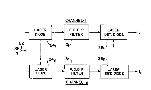
Figure 2 is an electrical block diagram of the preferred
embodiment of the invention utilizing fiber optic bandpass filters
as shown in Figure 1 in each of the channels.
DETAILED DESCRIPTION
Prior to considering the details of the subject invention, the
operation of a compressive receiver will first be described. A
compressive receiver is based upon pulse compression and is
formulated on the correlation properties of phase coded waveforms,
linear frequency modulation or chirps. SAW technology has
typically been used for pulse compression. One approach is to
employ a frequency mixer for the RF input and the output of a swept
-3-

l' ., r". P' t-',' r
or chirped local oscillator followed by a compressor implementing
what is known as a multiply long, convolve, short (ML-CS)
configuration. The chirp slopes of the sweeping local oscillator
and the compressor are designed to match so that an output defining
a sin x/x function is provided.
In the present invention, the heretofore used SAW filter ban~C
is replaced by an array of fiber optic filters designed as a bank
of bandpass filters.
~teferring now to Figure 1, shown thereat is a fiber optic RF
bandpass filter 10 comprised of a predetermined length of multimode
optic fiber 12 and a pair of dielectric mirror elements 14 and 16
deposited on each end. Small holes or apertures 18 and 20 are
formed in the mirrors 14 and 16 for the passage of optical energy
respectively in and out of the cavity 12. The cavity length is
chosen to be one half the modulation wavelength ~,m = c/fc where c
is the speed of light (3 x 10⁸m/sec) and f~ is the
frequency of modulation imposed on the carrier light injected into
the cavity 12. The cavity 12, therefore, is not resonant at the
frequency of the optical carrier, but to the modulation on the
carrier. Thus one would choose the length L to match the center
frequency of the band of modulation frequencies fC in accordance
with the expression L = c/2nfc where n is the refractive index of
the fiber. Operation with non-coherent light and/or a highly
multimode fiber results in averaging overoptical resonances within
the cavity. Thus the filter acts only on power variations and is
independent of the optical wavelength of the light carrier of the
energy entering the hole 18 into the cavity 12.
_4_

This now leads to a consideration of the preferred embodiment
of the invention which comprises an array of fiber optical bandpass
filter channels 1-n. Each of the bandpass filter channels are
coupled to an RF input which is receptive to a wide Y~and of
frequencies which can be separated into a plurality of spectrum
samples or frequency bins distributed over the frequency range of
interest.
Accordingly, each channel or frequency bin is comprised of a
fiber optic bandpass filter 101 so that the first channel includes
the filter 101, while the last channel includes the filter 10n.
Each of the fiber optic bandpass filters 101 - 10n are coupled to
the output of a respective laser diode 241 - 24n which is modulated
by the RF input at 22. Each of the bandpass filters 101 - 10n have
predetermined different center frequencies as determined by the.
respective lengths of the optical fibers 12 from which they are
fabricated. Each of the fiber optic bandpass filters 101 - 10n
have their respective optical outputs fed to respective laser
detector diodes 261 - 26n which in turn output frequencies f1 - fn
of the respective frequency bins. When desirable, the n number of
laser diodes can be replaced by a single laser diode and modulator
element 24 whose output would be commonly coupled to all of the
fiber optic bandpass filters 101 - 10n. The frequency outputs f1 -
fn when mixed or heterodyned with a swept local oscillator, riot
shown, provides IF signals.
Where the array of bandpass filters as shown iri Figure 2 axe
included in electronic support measure (ESM) receivers used for
electronic waveform applications, for example, there is provided an
-5-

improved means for detecting radar signals as well as their angles
of arrival and also to que direction finders, etc. over a ~fre~c~xency
range, for example, between 50oMHz and lBGHz.
Having thus shown and described what is at present considered
to be the preferred embodiment of the invention, it should be noted
that the same has been made by way of illustration and not
limitation. accordingly, all modifications, alterations and
changes coming within the spirit and scope of the invention are
herein meant to be included.
-6~-

Representative Drawing
A single figure which represents the drawing illustrating the invention.
Administrative Status

2024-08-01:As part of the Next Generation Patents (NGP) transition, the Canadian Patents Database (CPD) now contains a more detailed Event History, which replicates the Event Log of our new back-office solution.

Please note that "Inactive:" events refers to events no longer in use in our new back-office solution.

For a clearer understanding of the status of the application/patent presented on this page, the site Disclaimer , as well as the definitions for Patent , Event History , Maintenance Fee  and Payment History  should be consulted.

Event History

Description Date
Inactive: IPC expired 2013-01-01
Inactive: IPC from MCD 2006-03-11
Time Limit for Reversal Expired 2001-01-17
Letter Sent 2000-01-17
Grant by Issuance 1999-09-07
Inactive: Cover page published 1999-09-06
Pre-grant 1999-05-31
Inactive: Final fee received 1999-05-31
Letter Sent 1999-05-14
Notice of Allowance is Issued 1999-05-14
Inactive: Application prosecuted on TS as of Log entry date 1999-05-10
Inactive: Status info is complete as of Log entry date 1999-05-10
Inactive: IPC assigned 1999-04-15
Inactive: Approved for allowance (AFA) 1999-04-13
Request for Examination Requirements Determined Compliant 1994-02-02
All Requirements for Examination Determined Compliant 1994-02-02
Application Published (Open to Public Inspection) 1992-08-20

Abandonment History

There is no abandonment history.

Maintenance Fee

The last payment was received on 1998-11-28

Note : If the full payment has not been received on or before the date indicated, a further fee may be required which may be one of the following

  • the reinstatement fee;
  • the late payment fee; or
  • additional fee to reverse deemed expiry.

Please refer to the CIPO Patent Fees web page to see all current fee amounts.

Fee History

Fee Type Anniversary Year Due Date Paid Date
MF (application, 6th anniv.) - standard 06 1998-01-20 1997-10-21
MF (application, 7th anniv.) - standard 07 1999-01-18 1998-11-28
Final fee - standard 1999-05-31
Owners on Record

Note: Records showing the ownership history in alphabetical order.

Current Owners on Record
GOVERNMENT OF THE UNITED STATES, AS REPRESENTED BY THE SECRETARY OF THE ARMY (THE)
Past Owners on Record
CHARLES E. KONIG
Past Owners that do not appear in the "Owners on Record" listing will appear in other documentation within the application.
Documents

To view selected files, please enter reCAPTCHA code :


To view images, click a link in the Document Description column. To download the documents, select one or more checkboxes in the first column and then click the "Download Selected in PDF format (Zip Archive)" or the "Download Selected as Single PDF" button.

List of published and non-published patent-specific documents on the CPD .

If you have any difficulty accessing content, you can call the Client Service Centre at 1-866-997-1936 or send them an e-mail at CIPO Client Service Centre.


Document
Description 
Date
(yyyy-mm-dd) 
Number of pages   Size of Image (KB) 
Cover Page 1994-03-31 1 13
Abstract 1994-03-31 1 15
Claims 1994-03-31 2 53
Drawings 1994-03-31 1 15
Description 1994-03-31 6 194
Claims 1999-03-24 2 61
Drawings 1999-03-24 1 14
Representative drawing 1999-07-08 1 7
Representative drawing 1999-08-31 1 6
Cover Page 1999-08-31 1 31
Commissioner's Notice - Application Found Allowable 1999-05-14 1 165
Maintenance Fee Notice 2000-02-14 1 179
Correspondence 1999-05-31 1 39
Fees 1998-11-28 1 42
Fees 1997-10-21 1 44
Fees 1996-10-24 2 129
Fees 1995-11-06 2 144
Fees 1993-11-15 2 130
Fees 1994-10-14 2 124
Courtesy - Office Letter 1994-02-16 1 64
Prosecution correspondence 1992-01-17 8 431
Prosecution correspondence 1994-02-02 1 41
Prosecution correspondence 1994-02-02 2 42
Prosecution correspondence 1999-02-10 4 134
Examiner Requisition 1998-11-19 2 64
Prosecution correspondence 1994-02-02 2 42