Sélection de la langue

Search

Sommaire du brevet 2059587 

Énoncé de désistement de responsabilité concernant l'information provenant de tiers

Une partie des informations de ce site Web a été fournie par des sources externes. Le gouvernement du Canada n'assume aucune responsabilité concernant la précision, l'actualité ou la fiabilité des informations fournies par les sources externes. Les utilisateurs qui désirent employer cette information devraient consulter directement la source des informations. Le contenu fourni par les sources externes n'est pas assujetti aux exigences sur les langues officielles, la protection des renseignements personnels et l'accessibilité.

Disponibilité de l'Abrégé et des Revendications

L'apparition de différences dans le texte et l'image des Revendications et de l'Abrégé dépend du moment auquel le document est publié. Les textes des Revendications et de l'Abrégé sont affichés :

  • lorsque la demande peut être examinée par le public;
  • lorsque le brevet est émis (délivrance).
(12) Brevet: (11) CA 2059587
(54) Titre français: CANALISEUR A FIBRES OPTIQUES POUR SIGNAUX RF
(54) Titre anglais: FIBER OPTIC RF SIGNAL CHANNELIZER
Statut: Périmé et au-delà du délai pour l’annulation
Données bibliographiques
(51) Classification internationale des brevets (CIB):
  • H04B 1/16 (2006.01)
  • G01R 23/00 (2006.01)
  • G02B 6/34 (2006.01)
  • H04J 14/02 (2006.01)
(72) Inventeurs :
  • KONIG, CHARLES E. (Etats-Unis d'Amérique)
(73) Titulaires :
  • GOVERNMENT OF THE UNITED STATES, AS REPRESENTED BY THE SECRETARY OF THE ARMY (THE)
(71) Demandeurs :
  • GOVERNMENT OF THE UNITED STATES, AS REPRESENTED BY THE SECRETARY OF THE ARMY (THE) (Etats-Unis d'Amérique)
(74) Agent: KALEVI P. ASPILAASPILA, KALEVI P.
(74) Co-agent:
(45) Délivré: 1999-09-07
(22) Date de dépôt: 1992-01-17
(41) Mise à la disponibilité du public: 1992-08-20
Requête d'examen: 1994-02-02
Licence disponible: S.O.
Cédé au domaine public: S.O.
(25) Langue des documents déposés: Anglais

Traité de coopération en matière de brevets (PCT): Non

(30) Données de priorité de la demande:
Numéro de la demande Pays / territoire Date
07/656,916 (Etats-Unis d'Amérique) 1991-02-19

Abrégés

Abrégé anglais


An array of fiber optic RF filters each responsive to a
predetermined wavelength forms a channelizer for a wide bandwidth
receiver used in a dense signal environment having complex
modulations. Each fiber optic RF filter comprises a resonant
cavity formed from a section of multimode optic fiber with a
dielectric mirror deposited at each end and wherein the cavity
length corresponds to one half the respective modulation signal
wavelength of optical energy fed into the filter optic cavity from
a laser diode which is modulated by the received RF energy.

Revendications

Note : Les revendications sont présentées dans la langue officielle dans laquelle elles ont été soumises.


THE EMBODIMENTS OF THE INVENTION IN WHICH AN EXCLUSIVE
PROPERTY OR PRIVILEGE IS CLAIMED ARE DEFINED AS FOLLOWS:
1. A frequency channelizer for determining the frequency
of a plurality of received radio frequency signals over a
predetermined bandwidth, comprising:
a plurality of predetermined narrow bandwidth frequency
detection channels coupled to an RF signal input, each channel
including a fiber optic bandpass filter having a predetermined
different center frequency selectively chosen within said
predetermined bandwidth for channeling signals for detection
within a plurality of frequency bins.
2. The frequency channelizer of claim 1 wherein each fiber
optic bandpass filter is further comprised of a fiber optic
cavity and mirror means having light apertures therein located
at opposite ends of said cavity.
3. The frequency channelizer of claim 2 wherein said fiber
optic cavity is comprised of a length of optical fiber.
4. The frequency channelizer of claim 3 wherein the length
of said optical fiber is a function of the center frequency of
the bandpass of the respective filter.

5. The frequency channelizer of claim 3 wherein the length of
said optical fiber is substantially equal to one half the
wavelength of the respective center frequency.
6. The frequency channelizer of claim 3 and wherein said
mirror means comprises a pair of dielectric mirrors secured to each
end of said optical fiber.
7. The frequency channelizer of claim 1 and additionally
including light modulation means coupled to and responsive to said
RF signal input for generating a modulated optical signal which is
then coupled to each said fiber optic bandpass filter.
8. The frequency channelizer of claim 7 wherein said light
modulation means comprises laser diode means.
9. The frequency channelizer of claim 8 wherein said laser
diode means comprises a laser diode coupled between said RF signal
input and each said fiber optic bandpass filter.
10. The frequency channelizer of claim 7 and additionally
including light demodulation means coupled to each of said fiber
optic bandpass filter.
11. The frequency channelizer of claim 10 wherein said light
demodulation means comprises a laser detector diode.

Description

Note : Les descriptions sont présentées dans la langue officielle dans laquelle elles ont été soumises.

~~;'~~5~3'°~
FIELD OF THE INVENTION
This invention relates to the detection of a wide spectrum of
radio frequency signals and more particularly to the detection of
radio frequency signals in a dense signal environment with complex
modulations.
BACKGROUND OF THE INVENTION
Several frequency source identification methods are generally
known in the prior art. The mast well known of these is probably
what may be termed "standard heterodyning techniques'°. This
technique tunes a heterodyne receiver for peak output provides a
readout of the frequency in question. This technique is relatively
time consuming. and becomes impossible when the signal source is
hopping or changing rapidly in frequency. One known technique for
signal detection where signal hopping is involved involves the use
of a compressive receiver. In this type of receiver, an input
signal is mixed with a chirp signal and swept through the
intermediate frequency band for a designated time of arrival. The
signal's position and time is therefore indicative of its
frequency. One example of this type of apparatus is disclosed in
U.S. Pat. No. 4,443,801 issued to D.R. Klose et al, which issued on
April 17, 1984, and which discloses the use of SAW interferometer
processor apparatus which performs high resolution measurements on
multiple signals of different frequency.
A SAW channelizer compressive interferometer is a combination
of two basic and well known technologies, namely, a SAW channelizer
and a compressive interferometer. A conventional SAW channelizer
_x_

measures the pulsewidth (PW) , pi.alse ampl~.tude (PA) , arid time of
arrival (TOA) while compressive angles of arrival (AOA) channels
measure AOA and frequency. A SAW channelizer is comprised of a
contiguous bank of SAP7 filters arranged to sort the received signal
into frequency bins, with the frequency bin width being selected by
the minimum pulsewidths to be intercepted. The filters also have
sharp cut off frequencies to enable them to discern strong vs. weak
signals in adjacent channels. A compressive interferometer is a
spin off of a microscan receiver where AOA is measured from antenna
l0 input phase differentials along with the frequency of multiple
signals in the IF passband. Conventional SAW based compressive
interferometers, however, suffer from having too many filters in
the channelizer to measure pulsewidth.
SUMMARY OF THE TNVENTION
It is an object of the present invention, therefore, to detect
a wide spectrum of radio frequency signals, whether or not those
signals are received coincidentally.
It is a further object of the invention to provide an
improvement in a channelized type of RF receiver.
20 It is yet another object of the invention to provide an
alternate configuration for a wide band compressive interferometer
and SAW channelizer.
Briefly, the,foregoing and other objects of the invention are
provided by an array of fiber optic signal filters arranged as
bandpass filters to form a channelizer, with each filter being
_2_

~, ...,r~ e,., a.A~ t.°
constructed from a resonant cavity formed from a section of
multimode otpic fiber with a dielectric mirror disposed at each end
and whose respective cavity length corresponds to one half the
center frequency of the filter. Each channel,, moreover, includes
a laser diode connected between the RF input and the filter input
and a laser detector diode connected between the filter output and
a signal output,
BRTEF DESCRIPTION OF THE DRAWING
These and other objects, features and details of the invention
will become apparent in light of the ensuing detailed disclosure,
and particularly in light of the drawings wherein:
Figure 1 is a functional block diagram of a fiber optic
filter; and
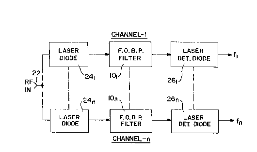
Figure 2 is an electrical block diagram of the preferred
embodiment of the invention utilizing fiber optic bandpass filters
as shown in Figure 1 in each of the channels.
DETAILED DESCRIPTION
Prior to considering the details of the subject invention, the
operation of a compressive receiver will first be described. A
compressive receiver is based upon pulse compression and is
formulated on the correlation properties of phase coded waveforms,
linear frequency modulation or chirps. SAW technology has
typically been used for pulse compression. One approach is to
employ a frequency mixer for the RF input and the output of a swept
-3-

l' ., r". P' t-',' r
or chirped local oscillator followed by a compressor implementing
what is known as a multiply long, convolve, short (ML-CS)
configuration. The chirp slopes of the sweeping local oscillator
and the compressor are designed to match so that an output defining
a sin x/x function is provided.
In the present invention, the heretofore used SAW filter ban~C
is replaced by an array of fiber optic filters designed as a bank
of bandpass filters.
~teferring now to Figure 1, shown thereat is a fiber optic RF
bandpass filter 10 comprised of a predetermined length of multimode
optic fiber 12 and a pair of dielectric mirror elements 14 and 16
deposited on each end. Small holes or apertures 18 and 20 are
formed in the mirrors 14 and 16 for the passage of optical energy
respectively in and out of the cavity 12. The cavity length is
chosen to be one half the modulation wavelength ~,m = c/fc where c
is the speed of light (3 x 10⁸m/sec) and f~ is the
frequency of modulation imposed on the carrier light injected into
the cavity 12. The cavity 12, therefore, is not resonant at the
frequency of the optical carrier, but to the modulation on the
carrier. Thus one would choose the length L to match the center
frequency of the band of modulation frequencies fC in accordance
with the expression L = c/2nfc where n is the refractive index of
the fiber. Operation with non-coherent light and/or a highly
multimode fiber results in averaging overoptical resonances within
the cavity. Thus the filter acts only on power variations and is
independent of the optical wavelength of the light carrier of the
energy entering the hole 18 into the cavity 12.
_4_

This now leads to a consideration of the preferred embodiment
of the invention which comprises an array of fiber optical bandpass
filter channels 1-n. Each of the bandpass filter channels are
coupled to an RF input which is receptive to a wide Y~and of
frequencies which can be separated into a plurality of spectrum
samples or frequency bins distributed over the frequency range of
interest.
Accordingly, each channel or frequency bin is comprised of a
fiber optic bandpass filter 101 so that the first channel includes
the filter 101, while the last channel includes the filter 10n.
Each of the fiber optic bandpass filters 101 - 10n are coupled to
the output of a respective laser diode 241 - 24n which is modulated
by the RF input at 22. Each of the bandpass filters 101 - 10n have
predetermined different center frequencies as determined by the.
respective lengths of the optical fibers 12 from which they are
fabricated. Each of the fiber optic bandpass filters 101 - 10n
have their respective optical outputs fed to respective laser
detector diodes 261 - 26n which in turn output frequencies f1 - fn
of the respective frequency bins. When desirable, the n number of
laser diodes can be replaced by a single laser diode and modulator
element 24 whose output would be commonly coupled to all of the
fiber optic bandpass filters 101 - 10n. The frequency outputs f1 -
fn when mixed or heterodyned with a swept local oscillator, riot
shown, provides IF signals.
Where the array of bandpass filters as shown iri Figure 2 axe
included in electronic support measure (ESM) receivers used for
electronic waveform applications, for example, there is provided an
-5-

improved means for detecting radar signals as well as their angles
of arrival and also to que direction finders, etc. over a ~fre~c~xency
range, for example, between 50oMHz and lBGHz.
Having thus shown and described what is at present considered
to be the preferred embodiment of the invention, it should be noted
that the same has been made by way of illustration and not
limitation. accordingly, all modifications, alterations and
changes coming within the spirit and scope of the invention are
herein meant to be included.
-6~-

Dessin représentatif
Une figure unique qui représente un dessin illustrant l'invention.
États administratifs

2024-08-01 : Dans le cadre de la transition vers les Brevets de nouvelle génération (BNG), la base de données sur les brevets canadiens (BDBC) contient désormais un Historique d'événement plus détaillé, qui reproduit le Journal des événements de notre nouvelle solution interne.

Veuillez noter que les événements débutant par « Inactive : » se réfèrent à des événements qui ne sont plus utilisés dans notre nouvelle solution interne.

Pour une meilleure compréhension de l'état de la demande ou brevet qui figure sur cette page, la rubrique Mise en garde , et les descriptions de Brevet , Historique d'événement , Taxes périodiques et Historique des paiements devraient être consultées.

Historique d'événement

Description Date
Inactive : CIB expirée 2013-01-01
Inactive : CIB de MCD 2006-03-11
Le délai pour l'annulation est expiré 2001-01-17
Lettre envoyée 2000-01-17
Accordé par délivrance 1999-09-07
Inactive : Page couverture publiée 1999-09-06
Préoctroi 1999-05-31
Inactive : Taxe finale reçue 1999-05-31
Lettre envoyée 1999-05-14
Un avis d'acceptation est envoyé 1999-05-14
Inactive : Dem. traitée sur TS dès date d'ent. journal 1999-05-10
Inactive : Renseign. sur l'état - Complets dès date d'ent. journ. 1999-05-10
Inactive : CIB attribuée 1999-04-15
Inactive : Approuvée aux fins d'acceptation (AFA) 1999-04-13
Exigences pour une requête d'examen - jugée conforme 1994-02-02
Toutes les exigences pour l'examen - jugée conforme 1994-02-02
Demande publiée (accessible au public) 1992-08-20

Historique d'abandonnement

Il n'y a pas d'historique d'abandonnement

Taxes périodiques

Le dernier paiement a été reçu le 1998-11-28

Avis : Si le paiement en totalité n'a pas été reçu au plus tard à la date indiquée, une taxe supplémentaire peut être imposée, soit une des taxes suivantes :

  • taxe de rétablissement ;
  • taxe pour paiement en souffrance ; ou
  • taxe additionnelle pour le renversement d'une péremption réputée.

Veuillez vous référer à la page web des taxes sur les brevets de l'OPIC pour voir tous les montants actuels des taxes.

Historique des taxes

Type de taxes Anniversaire Échéance Date payée
TM (demande, 6e anniv.) - générale 06 1998-01-20 1997-10-21
TM (demande, 7e anniv.) - générale 07 1999-01-18 1998-11-28
Taxe finale - générale 1999-05-31
Titulaires au dossier

Les titulaires actuels et antérieures au dossier sont affichés en ordre alphabétique.

Titulaires actuels au dossier
GOVERNMENT OF THE UNITED STATES, AS REPRESENTED BY THE SECRETARY OF THE ARMY (THE)
Titulaires antérieures au dossier
CHARLES E. KONIG
Les propriétaires antérieurs qui ne figurent pas dans la liste des « Propriétaires au dossier » apparaîtront dans d'autres documents au dossier.
Documents

Pour visionner les fichiers sélectionnés, entrer le code reCAPTCHA :


Pour visualiser une image, cliquer sur un lien dans la colonne description du document. Pour télécharger l'image (les images), cliquer l'une ou plusieurs cases à cocher dans la première colonne et ensuite cliquer sur le bouton "Télécharger sélection en format PDF (archive Zip)" ou le bouton "Télécharger sélection (en un fichier PDF fusionné)".

Liste des documents de brevet publiés et non publiés sur la BDBC .

Si vous avez des difficultés à accéder au contenu, veuillez communiquer avec le Centre de services à la clientèle au 1-866-997-1936, ou envoyer un courriel au Centre de service à la clientèle de l'OPIC.


Description du
Document 
Date
(aaaa-mm-jj) 
Nombre de pages   Taille de l'image (Ko) 
Page couverture 1994-03-31 1 13
Abrégé 1994-03-31 1 15
Revendications 1994-03-31 2 53
Dessins 1994-03-31 1 15
Description 1994-03-31 6 194
Revendications 1999-03-24 2 61
Dessins 1999-03-24 1 14
Dessin représentatif 1999-07-08 1 7
Dessin représentatif 1999-08-31 1 6
Page couverture 1999-08-31 1 31
Avis du commissaire - Demande jugée acceptable 1999-05-14 1 165
Avis concernant la taxe de maintien 2000-02-14 1 179
Correspondance 1999-05-31 1 39
Taxes 1998-11-28 1 42
Taxes 1997-10-21 1 44
Taxes 1996-10-24 2 129
Taxes 1995-11-06 2 144
Taxes 1993-11-15 2 130
Taxes 1994-10-14 2 124
Courtoisie - Lettre du bureau 1994-02-16 1 64
Correspondance de la poursuite 1992-01-17 8 431
Correspondance de la poursuite 1994-02-02 1 41
Correspondance de la poursuite 1994-02-02 2 42
Correspondance de la poursuite 1999-02-10 4 134
Demande de l'examinateur 1998-11-19 2 64
Correspondance de la poursuite 1994-02-02 2 42