Note: Descriptions are shown in the official language in which they were submitted.
2~5~2~
DUAL-PURPOSE TRAILER
Background of the Invention
The present invention relates to recreational
vehicles, and particularly to a trailer to be towed
behind a motor home for carrying a small boat and towing
a small automobile economically and from which the boat
can easily be launched.
In recent years, motor homes have come into
widespread use as a way to travel economically to vaca-
tion destinations. While such vehicles save the cost of
hotel or motel lodging while providing a comfortable
place to eat and sleep, motor homes are somewhat unhandy
because o~ their size. It has become common, then, to
tow a small automobile behind a large motor home, so that
the small automobile can be used locally around a
vacation destination.
In order to avoid the costs and inconveniences
of boat rental, small boats are also often brought along
on trips. In the past, this has sometimes been accom-
plished by carrying a small boat atop a motor home, which
severely limits the size of boat which can be trans-
ported. Alternatively, a small boat can be fastened atop
a smaller vehicle being towed, if that vehicle is large
enough and the boat small enough.
Another alternative is the use o~ a trailer to
carry both a boat and an automobile. Trailers useful in
such a manner have been shown, for example, in Woodburn
U.S. Patent No. 4,932,830 and McDonald U.S. Patent No.
4,406,477, each of which depicts a trailer including a
frame on which a boat may be loaded. The frame is then
raised along a set of upright posts to provide room for
an automobile to be driven onto the trailer to be carried
beneath the boat. Such trailers are quite heavy, result-
ing in a substantial amount of weight which must be
towed, and they are unnecessarily large for carrying
small boats.
;.i :. , ;
2~9~2~
Cravens et al. U.S. Patent No. 4,880,250
discloses a somewhat different arrangement in which a
boat and boat trailer are backed onto a specially
equipped trailer, after which the boat and boat trailer
are raised, providing room for an automobile to be driven
onto the trailer. Weber U.S. Patent No. 4,705,289 shows
another trailer in which a boat trailer and boat are
carried together above an automobile carried entirely on
the platform of the trailer. These are undesirably heavy
trailers for towing behind a motor home.
Drahos U.S. Patent No. 4,923,243 shows a
trailer including a forward extension upon which a boat
trailer carrying a boat can be carriedD This also
results in a larger and heavier trailer than is desirable
for towing behind a motor home. Hastings U.S. Patent No.
3,843,161 and Modglin U.S. Patent No. 3,446,516 show
other trailers equipped with elongated tongues including
space for supporting boats. None of these last three
mentioned patents, however, provides an economical way
for a single driver to bring a small automobile and a
small boat along with a motor home.
What is desired, then, is a trailer of
relatively light weight, by means of which a small auto--
mobile and a boat may be towed conveniently behind a
motor home) without making the combination of motor home
and towed vehicles so long as to be unmanageable or
unsafe, and without requiring so much power that travel
is unduly slowed.
Summary of the Invention
The aforementioned shortcomings of the prior
art are overcome by the present invention, which provides
a dual-purpose trailer of relatively light weight, which
carries a small boat, such as a fishing boat equipped
with an outboard motor, and permits the boat to be
launched and recovered using the trailer in the same
fashion as a conventional single-purpose boat trailer.
:~ . ,- .i
i :-
.. . ..
. ,~ , ' ' " ' , ~ .
,
., ~
., . . :
2~9621
The trailer of the present invention also allows one end
of a small automobile to be driven onto the trailer. As
a result, the automobile can be towed closely enough
behind a motor home so that the combination of the motor
home, trailer, and towed automobile is short enough and
light enough to be handled easily when traveling on
highways.
A trailer in accordance with the present
invention includes a main frame supported by a pair of
road wheels attached conventionally to the main frame.
The main frame has a forwardly-extending tongue equipped
with a conventional hitch arrangement, and supports a
platform for receiving and supporting a pair of wheels of
a small automobile.
In a preferred embodiment of the invention the
trailer includes a centrally pivoted wheel support sub-
assembly, equipped with a pair of pivoted ramps, up which
an automobile's wheels can be driven so that the weight
of one end of the automobile is then carried upon the
trailer. In such a preferred embodiment of the invention
the ramps are attached pivotably to the rear of the wheel
support subassembly in such a way that the weight of the
automobile on the trailer holds the ramps clear of the
ground when the automobile is in position for towing.
Also carriad upon the main frame of the trailer
is a boat support frame whose front end is supported near
the front of the trailer. The boat support frame is
equipped with the usual keel rollers, bilge chocks and
launching winch for supporting a boat adequately and
facilitating launch and recovery. The rear end of the
boat support frame can be raised and lowered between a
lowered position for boat launching and recovering and a
raised position in which the boat support frame is sup-
ported by a pair of legs spaced apart laterally far
enough from each other to receive an automobile between
the legs. When the legs are in an upright position they
support the boat support frame with its rear end high
,, ~ . -., ,
:, :,
., .
~. , :
2 ~ 2 1
enough to provide clearance for the towed automobile on
the trailer beneath the boat support ~rame.
In a preferred embodiment of the invention the
legs which carry the boat support frame in its raised
position are interconnected with each other as an arch
frame, with the lower ends of the legs o~ the arch
attached to the main frame of the trailer. The trans-
verse horizontal member of such an arch frame is con-
nected with longitudinal side members of the boat support
frame by a pair of slides disposed in channels defined by
the longitudinal side members of the boat support frame.
The boat support plat~orm is ~hus supported at three
spaced-apart places, giving ample lateral stability.
In a preferred embodiment of the invention a
cable and winch are used to move the arch frame between
its upright position and its rearwardly-extending,
lowered, position. While other devices, such as
hydraulic cylinder-and-piston assemblies, could be used
to raise and lower the arch frame relative to the main
frame of the trailer, the cable and winch assembly is
preferred because of its lower cost and greater
simplicity.
The present invention therefore provides an
inexpensive dual-purpose trailer ~or carrying a boat and
towing a small motor vehicle behind a motor home or other
suitably powerful vehicle.
The present invention also provides a trailer
for use in towing an automobile and also capable of
launching and recovering a small boat in the same manner
as a conventional boat trailer.
The present invention further provides such a
trailer which is amply strong yet lighter in weight than
previously available trailers for transporting both a
boat and an automobile.
It is an important feature of one embodiment of
the present invention that it provides a trailer includ-
ing a boat support frame that can be moved to a raised,
," - .
-.................... ~ ,, ; ; . ,
- . : .
, ~,
.,
.
- 2 ~ ' 2 1
forwardly-inclined position, providing room for support-
ing one end of an automobile beneath a boat carried on
the trailer.
It is another important feature of one
embodiment of the present invention that it provides a
trailer including a boat support frame which can be moved
to a position allowing the trailer to be used in th~ same
fashion as a conventional boat trailer for launching and
recovering a boat.
The foregoing and other objectives, features,
and advantages of the invention will be more r~adily
understood upon consideration of the following detailed
description of the invention, taken in conjunction with
the accompanying drawings.
Brief Description of the Drawings
FIG. 1 is a side elevational view o~ a dual-
purpose trailer according to the present invention, show-
ing a boat carried on the trailer in a raised position
and showing the manner in which a small automobile is
placed upon the trailer to be towed.
FIG. 2 is a side elevational view of the
trailer shown in FIG. 1, with its boat support frame in
its lowered position, in which the boat can be launched
or recovered as with an ordinary boat trailer.
FIG. 3 is a top plan view of the trailer shown
in FIGS. 1 and 2, with the boat support frame in the
position shown in FIG. 2.
FIG. 4 is a sectional view taken along line 4-
4 of FIG. 1, showing the upper end of the arch frame andthe arrangement of slider members in the channels defined
by the boat support frame of the dual-purpose trailer
shown in FIG. 1.
FIG. 5 is a top plan view of the rear portion
of a boat trailer similar to that shown in FIG. 3 and
incorporating a torsion bar suspension arrangement
adapted for carrying heavier boats.
.. .
.. .
- ` . , : ,, ' . ;-
: ,, ., :
- ~ }~ , :
. : : . " . .
:, . . . : .
: "
., , .. , ~ .:
2 ~ 2 ~
FIG. 6 is a sectional view taken along line 6-6
of FIG. 5, showing a detail of the torsion bar suspension
arranyement shown in FIG. 5.
FIG. 7 is a sectional detail view taken along
line 7-7 of FIG. 6.
FIG. 8 is a top plan view of the wheel support
subassembly and a portion of the main frame of the multi-
purpose trailer shown in FIG. 3, at an enlarged scale.
FIG. 9 is a sectional view taken along line 9-
9 of FIG. 8, showing the operation of the loading rampsassociated with the wheel support subassemblyO
Detailed Description__f the Preferred Embodiments
Referring now to the drawings which form a part
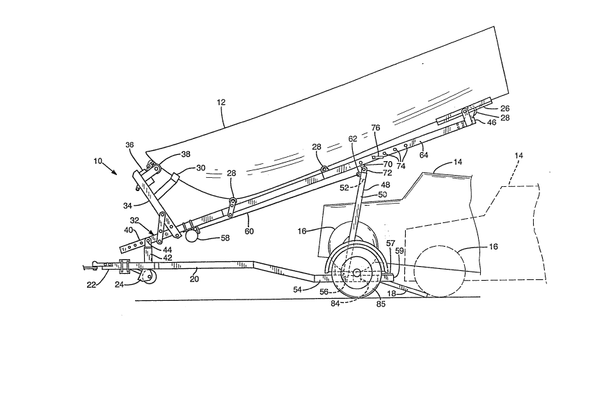
of the disclosure herein, in FIG. 1, a trailer 10 accord
ing to the present invention is shown with a boat 12
carried thereon. The trailer 10 is preferably con-
structed of steel stock such as square tubing and formed
plate of suitable strength, welded together, utilizing
suitable gussets for strengthening at corners and incor-
porating a conventional drop axle, wheels, and wheel
bearings and suitable pneumatic tires to accommodate
uneven road surfaces. A portion of an automobile 14 is
shown with its front road wheels carried upon the trailer
10. The automobile 14 is also shown in broken line with
its front road wheels 16 at the rear ends of a pair of
loading ramps 18 which are part of the trailer 10, as
will be explained more fully presently.
The trailer 10 includes a main frame 20 having
a front end 22 including a tongue equipped with the usual
ball-gripping hitch and a jack stand 24 for supporting
the front end 22 when the trailer is not hitched to a
towing vehicle. The boat 12 is supported by bilge blocks
26, keel rollers 28, and bow chock 30 such as are found
on an ordinary boat trailer and which are attached to a
boat support frame 32. A forward upright member 34 of
the boat support frame 32 carries the bow chock 30, as
. , . ~ . .,
.~ '` ':
2 ~
well as a loading winch 36 and winch roller chock 38,
which may be fastened to the upright member 34 at a
selected one of several positions defined by a series of
bolt holes (not shown) in a preferred embodiment of the
invention. A cable wound upon the winch 36 may be used
to launch and recover the boat 12 by backing the trailer
10 down a suitable inclined boat launching ramp into
water deep enough to float the boat 12, when the boat
support frame 32 is in its lowered position as shown in
FIG. 2.
A front end 40 of the boat support frame 32 is
supported above the front end ~2 of the main frame 20 by
an upright post 42 whose height is preferably adjustable
by means such as the provision of a pin and a plurality
of vertically apart-spaced holes (not shown) in tele-
scoping inner and outer tubes. A pivot bearing 44 is
provided at the upper end of the upright post 42 and
provides a transverse horizontal axis of rotation for the
boat support frame 32 to permit the boat support frame 32
to be pivoted about a transverse horizontal axis estab-
lished by the bearing 44. The rear end 46 of the boat
support frame 32 can thus be moved between the lowered
position shown in FIG. 2 and the raised position shown in
FIG. 1. The front end 22 of the main frame and the front
end 40 of the boat support frame 32 may be adjustable in
length, if desired, to accommodate boats of different
lengths.
Referring now also to FIG. 3, an arch frame 48
includes a pair of parallel lifting legs 50 and a hori-
zontal transverse member 52 defining the upper end of thearch frame 48. The lower end of each lifting leg 50 is
attached to the outer side of a respective longitudinal
side member 54 of the main frame 20 by a respective pivot
bearing 56. The pivot bearings 56 establish a transverse
horizontal axis about which the arch frame 48 rotates
between a generally rearwardly-extending, nearly hori-
zontal, upwardly-sloping position of the lifting legs 50,
: .
~" ~
.:
, . -: , . . :
2 ~ 2 ~ .
as shown in FIGS. 2 and 3, and the substantially upright
raised position of the lifting legs 50, as shown in
FIG. 1. In order to facilitate lifting the boat support
frame 32 from its lowered position to its raised posi-
tion, the bearings 56 should be placed as low as prac-
tical with respect to the main frame 20, as will be
appreciated presently. Suitable rubber pads 57 may be
provided atop outwardly-angled rear end extensions 59 of
the side members 54 to cushion and support the lifting
legs 50 when the boat support frame 32 is located in the
lowered position shown in FIG. 2.
A boat-raising winch 58 i5 attached to the
boat-support frame 32 near its front end 40, preferably
by being clamped to the bottom of a central longitudinal
member 59 of the boat support frame 3~. A flexible
tension-bearing cable 60 extends from the winch 58 to a
padeye 62 located centrally on the horizontal transverse
member 52. An end of the cable 6Q is attached to the
padeye 62 by conventional means so that winding the cable
60 upon the winch 58 raises the arch frame 48, pivoting
the lifting legs 50 about the bearings 56 from the rear-
wardly-extending lowered position of the arch frame 48
toward its upstanding position as shown in FIG. 1.
The boat-raising winch 58 may be a manual winch
in a trailer 10 designed for a small, light boat 12. An
electrically powered winch with an automatic brake and
ample capacity is preferred for a trailer 10 on which a
larger boat is to be carried. The cable 60 must also be
of suitable strength, considering the load to be
encountered, which is greatest when commencing the move-
ment from the lowered position shown in FIG. 2 to the
raised position shown in FIG. 1. The tension in the
cable 60 must overcome the combined weight of the rear
portion of the boat support frame 32 and the boat 12,
with that weight applied against the cable 60 through a
mechanical advantage of the ratio of the distance A
divided by the distance B, shown in FIG. 2 when
'. ,;,~."- . - ~ .:
: . :
: : .. ; ., . : :
,;, .
., . .:
. . .
2~62~
commencing movement of the boat from the lowered position
sho~n in FIG. 2. The rearward position of the arch frame
48 i5 limited by the pads 57 on the frame member exten-
sions 59 to ensure that a great enough lever arm vertical
component is available.
As shown in greater detail in FIG. 4, the boat
support frame 32 includes longitudinal side members 64 of
structural metal, each de~ining a laterally inwardly-
facing channel 66. A slider member 6~, which is pref-
erably made of a suitable low-friction plastics material,
is disposed within each of the channels 66. The slider
members 68 are held spaced an appropriate distance apart
from each other by a transverse spacer bar assembly 69,
which is pivotably connected with the transverse hori-
zontal member 52 of the arch frame 48, as by a respective
ear 70 on the spacer bar assembly 69 fitting between and
attached by a pivot pin to a corresponding pair of ears
72 fixedly attached to the transverse horizontal member
52.
Each of the longitudinal side members 64
defines a plurality of locking bar holes 74 located oppo-
site corresponding locking pin holes 74 defined by the ~-
opposite one of the side members 64. A locking bar 76
extends through both of a selected pair of such locking
bar holes 74, as a stop to prevent the slider members 68
from moving rearwardly within the channels 66 when the
boat support frame 32 is in the raised position, sup-
ported by the arch frame 48 in its upright position. The
locking bar 76 is preferably provided with a suitable
locking device such as a toggle (not shown) to prevent it
from inadvertently working loose from its position in a
pair of locking bar holes 74.
A transverse member 77 extends b~tween the
longitudinal side members 64 at the r~ar end 46, and may
be attached in a selected position depending on the
length of the boat 12 by use of fasteners in appropriate
bolt holes 78 in the longitudinal side members 64.
. . .
:
. . .
2~6~
As may be seen in FIGS . 5, 6 and 7, a slightly
different slider arrangement may be provided in a trailer
10 designed for carrying a heavier boat. While the
arrangement of slider members ~8 as shown in FIGS. 1-4 is
suitable for boats whose weight may be as great as 700
lbs, heavier boats, particularly those of fiber-
reinforced plastic construction, may be more easily
damaged by jolts and vibration resulting from towing the
trailer 10 along uneven road surfaces. As shown in
FIGS. 5 and 6, a torsion bar assembly 79 replaces the
spacer bar assembly 69 and holds a pair of slider members
80, generally similar to the sliders 68, disposed in the
channels 66. A pair of torsion bar levers 82 connect the
torsion bar assembly 79 ~o the ears 72 of the ~ransverse
horizontal member 52, providing cushioning in the trans-
fer of forces through the arch frame 48 between the main
frame 20 and the boat support frame 32. Such a torsion
bar assembly includes an outer tube 83 of square section
shape, and an inner member 87, located within the outer
tube 83 and separated from it by an elastic layer 89 of
compressible material. Such a torsion bar assembly is
available from Dexter Industries of Elkhart, Indiana as
its 1000 lb-2500 lb TorflexTM torsion bar axle assembly.
As may be seen best in FIGS. 3 and 5, the boat
support frame 32 is substantially narrower than the main
frame 20, while the arch frame 48 is slightly wider than
the main frame 20, to provide room to receive one end of
the automobile 14 beneath the boat support frame 32, with
the wheels of the automobile 14 supported above but
slightly ahead of the main axle 84 of the main frame 20.
The main axle 84 is preferably a drop-center axle o~
conventional construction and may be equipped with
suitahle brakes for the wheels 85.
A main frame transverse member 86 extends
between the longitudinal side members 54. A main frame
rear transverse member 88, which may be the central,
lower part of the main axle 84 supporting the main frame
tv
, ~ : . ,, , ,:, .:
, ! . , :
' ~ , ' ' ,,,` , ' ' ' ' :" : ,
2~621
11
20 and carrying the road wheels 85 of the trailer 10,
extiends between the longitudinal side members 54 a short
distance rearwardly of the main frame transverse member
~6. A central longitudinal plate 90 extends horizontally
between the transverse members 86 and 88 and carries a
bearing 92 defining a vertical axis of rotation. A
vertical pin 93 attaches the center of a towed vehicle
support assembly 94 to the main frame 20, providing the
connection for transferring towing forces to the
automobile 14.
The towed vehicle support assembly 94 includes
a main cross member 96 of suitable size and material such
as a rectangular steel tube to carry towing forces to the
bearing 92. ~ pair of wheel support platforms 38 are
attached to the main cross member 96, as by suitable
welded joints. A chock plate 100 slopes forwardly and
upwardly from each wheel support platform 98 to support
the front of the tire of a respective one of the front
road wheels 16 of the automobile 14 and provides a place
for attaching a hold-down strap (not shown) for securing
the automobile 14, as may also be seen in FIGS. 8 and 9.
A loading ramp 18 is attached to the rear end
of each wheel support platform 98 by suitable pivot pins
104 extending through parallel mounting ears 106 and 108
included respectively in each wheel support platform 98
and the bottom of each loading ramp 18. The forward end
of each loading ramp 18 includes a forwardly-inclined
chock face 110. As the wheels 16 of the automobile 14
proceed up the loading ramps 18 to a point beyond the
horizontal transverse pivot axis 112 established by the
pivot pins 104, the loading ramps 18 are free to rotate
from the position shown in broken line to the position
shown in solid line in FIG. 9. The chock faces 110, each
engaging the rear portion of the tire of the respective
road wheel 16, thereafter help prevent the automobile 14
from rolling rearwardly out of its desired position on
the towed vehicle support assembly 94.
, , - . , ;:
, .; :
,:
,: . , ~ .: ,
:, : ,,
~, :. , , : , :
2 ~ ? 1
Longitudinal structures 116 interconnec~ the
transverse members 86 and 88 a small distance from each
side member 54 and a suitable bearing, such as a block
114 of low-friction plastic, fastened to the top o~ each
horizontal member 116, provides the principal support for
transferring vertical forces of the carried portion of
the weight of the automobile 14 to the main axle member
84 for each side of the trailer 10 through the wheel
support platforms 98.
A control arm 120 is attached to the front of
each of the loading ramps 18 and extends laterally out-
ward beyond the respective wheel support platform 98, so
that when the arch frame 48 is lowered to its rearwardly-
extending generally horizontal position, the lifting legs
50 engage the control arms 120 and push them down, rais-
ing the loading ramps 18 clear of the ground. This
obviates the need for any separate fasteners to keep the
loading ramps 18 from dra~ging on the ground.
Whenever the trailer 10 is not being used to
tow an automobile 14, the boat-support frame 32 should be
lowered to the position shown in FIG. 2, in order to
lower the center of gravity of th~ trailer 10. This will
raise the loading ramps 18, and the need to raise the
loading ramps 18 will also act as a reminder that the
boat 12 should be lowered whenever the automobile 14 is
not being towed.
The terms and expressions which have been
employed in the foregoing specification are used therein
as terms of description and not of limitation, and there
is no intention, in the use of such terms and expres-
sions, of excluding equivalents of the features shown and
described or portions thereof, it being recognized that
the scope of the invention is defined and limited only by
the claims which follow.
,. ~ , . .... . . . .
.
' ~