Note: Descriptions are shown in the official language in which they were submitted.
NHL-DH-26 CA
20~968~
DIAGNOSTIC DEVICE FOR THE EXAMINATION OF BIOLOGICAL MATERI~L
BACKGROUND OF THE INVENTION
1. Field of the Invention:
This invention relates to a portable diagnostic device for
the examination of biological samples. In particular, one exam-
ple of a use of such a portable examination device is for the ex-
amination of a biological specimen which contains substances
related to ovulation. Because of the size and ease of operation
of the device, the device is essentially suitable for use in
self-administered examinations.
2. Back~round Information:
One special application in which a portable and easy to use,
self-examinatlon device would generally be desirable is, for
example, in the determination of a woman's fertile period. Such
a determination could be very useful for any woman attempting to
have a child, or more particularly, for instances in which a
woman might be having difficulty in becoming pregnant. If a
woman was more aware of when her fertile period was occurring,
she would essentially know of the most appropriate time to at-
tempt to become pregnant.
It is generally known that during a woman's fertile period,
various additional bodily substances are formed which are not
normally present in the body fluids, and it has been determined
that some of these bodily substances can form special optical
structures when dried. Thus, in order to help determine the
ovulation period of women, it has been found that, if, during a
woman's fertile period, a saliva sample is taken and dried, vein-
like, or streaky structures are generally formed. During other
periods, however, a dried saliva sample typically only shows a
spotted, or dot-like pattern.
NHL-DH-26 CA
20~9~1
In general, these special optical structures can be seen
upon magnification, so that upon visual examination, the presence
or absence of these structures can essentially provide a "yes" or
"no" answer regarding the occurrence of a woman's fertile period.
Examination devices which enables such bodily substances to
be vie~ed, can be designed, for example, as microscopes or magni-
fying glasses, but on account of their design and construction,
known devices are basically suitable, in particular, only for
stationary operation. Typical known devices generally require
special precautions against damage to guarantee correct long-term
operation. In particular, the devices of the prior art are not
suitable for use as portable devices for the performance of
self-administered examinations.
OBJECT OF THE INVENTION
The object of the invention is therefore to improve a diag-
nostic device of the type described above, so that the device can
be manufactured economically and so that the device can be used
as a portable self-examination device.
SUMMARY OF THE INVENTION
_ _
This object is achieved by the present invention in that,
the device of the present invention preferably provides, in a
simple, hand-held device, a housing within which can be posi-
tioned an a~ least partly transparent slide, a radiant illumina-
tion device for illuminating the slide and positioned at some
distance from the slide, and a lens system for optically magnify-
ing the substances located on the slide. In particular, the
housing of the device can be of a size which allows the device to
be carried in the pockets of various articles of clothing, there-
by allowing the device to be portable for use whenever use of the
device is desired.
As a result of the configuration of the invention, it is
possible to perform the test for determining a woman's fertile
NHL-D~
period at almost any desired place and time. In addition, on
account of its compact design and construction, for example, the
device can be carried in a pocket or in a handbag, and is essen-
tially ready for use at any time. In one configuration of the
invention, the saliva sample can be placed on the slide, and
follo~ing a subsequent drying, it is possible, by means of the
illumination apparatus, to generate the desired image brightness,
and, by means of the lens system, to optically enlarge the speci-
men so that the specimen can be visually examined.
On account of the relatively simple structure and the rela-
tively simple operation of the device according to the invention,
the performance of the test for determining a woman's fertile
period using the device of the present invention takes essential-
ly very little time. In addition, in the event of an unclear
test result, the test can be repeated as many times as desired
within a relatively short period of time.
To make possible a simple mechanical arrangement and to
guarantee sufficient ease of operation, the present invention
proposes that the illumination apparatus be preferably located
within the housing. This can essentially be done by preferably
mounting the illumination device on a housing insert, which in-
sert can easily be inserted into and removed from housing. In
one particularly easy type of operation, the housing insert can
preferably be inserted into the housing in the direction of the
longitudinal axis of the housing.
To prevent an unintentional separation of the individual
parts used, that is, the housing insert from the housing, the
invention proposes that the housing insert preferably be provided
with a catch for engaging an opposing member of the housing,
thereby fixing the insert releasably in an inserted position
within the housing.
NHL-DH-26 CA
2~9681
Sufficient safety without the danger of interfering with the
insertion process can be achieved if the catch preferably con-
sists of at least one recess, which recess can be located in the
vicinity of a side wall of the housing insert, and a correspond-
ing latch or pin to engage the catch of the insert, which latch
or pin can be located on an internal side wall of the housing.
To adjust the examination device to different optical con-
ditions, and also to adjust the device to the different visual
acuities of the users, the present invention proposes an embodi-
ment in which the lens system is preferably equipped with at
least one lens, and the lens is preferably movable towards and
away from the slide to allow for adjustments in the visual clari-
ty of the enlarged image of the sample.
A particularly simple optical adjustment can be achieved if
the optics, which include at least one lens, are preferably ar-
ranged in or on a shaft equipped with an external thread, and
this threaded shaft can be designed to preferably engage with an
internal thread of a connecting piece of the housing. To alter
the optical enlargement achievable by the lens system, without
going exceedingly beyond the dimensions of the present invention,
any feasible variety and combination of lenses can be used in the
optical piece.
To make operation of the device according to the present
invention as easy as possible, the present invention proposes an
embodiment in which the slide can preferably be oriented so that
it can be inserted laterally into the housing.
In addition, a defined positioning of the housing insert
inside the housing can be possible because the housing preferably
has guide elements extending in the direction of the longitudinal
axis of the housing. These guide elements can essentially pre-
cisely guide the housing insert into the housing.
NHL-DH-26 CA
20~968~
Another embodiment of the examination device makes it possi-
ble to grasp the housing with one hand while performing the op-
erating procedures with the other hand. The present invention
also proposes that, in the vicinity of a grip on the housing
insert, there is preferably an actuator of a sliding switch for
turning the illumination device on and off, which sliding switch,
when the housing is held vertically with the lens arrangement on
top, essentially is located on the bottom of the housing.
The housing insert can also provide storage space for stor-
ing additional slides. Thus, long-term usage of the magnifica-
tion device can essentially be guaranteed because there can be a
number of included replacement slides. In addition, because of
the extra included slides, a few specimen samples could be pre-
pared simultaneously to allow for quick cross-checking of the
results of any one slide.
To provide an economical energy supply, the invention pro-
poses that at least one battery preferably be located within the
housing insert. This battery can essentially provide the power
needed to light the illumination device, which illumination de-
vice can be a light bulb.
One aspect of the invention resides broadly in a portable
diagnostic device for the examination of biological material, in
particular for the examination of a specimen containing sub-
stances which are produced as a function of ovulation. The diag-
nostic device comprises: a housing having a first end and a
second end with a longitudinal axis disposed along a length of
the housing between the first end and the second end, and a
transverse axis disposed along a width of the housing; a recepta-
cle disposed within the housing for receipt of the biological
material specimen, the receptacle being removable from the hous-
ing for placing the biological material specimen on the recepta-
cle and removing the biological material specimen from the
NHL-DH-26 CA
205~
receptacle; a device for examining the biological material speci-
men, the device for examining the biological material specimen
for being disposed at a first end of the housing; and an appara-
tus for enhancing examination of the biological material speci-
men.
Another aspect of the invention resides broadly in a porta-
ble diagnostic device for the examination of biological samples,
the biological samples for being disposed on a receptacle, the
diagnostic device comprising a housing, and the housing having a
first end and a second end with a longitudinal axis disposed
therebetween. The housing comprises: apparatus for holding the
receptacle means within the housing; an apparatus for illuminat-
ing the samples on the receptacle; and a device for viewing the
sample located on the receptacle means.
BRIEF DESCRIPTION OF THE DRAWINGS
Preferred embodiments of the invention are illustrated in
the accompanying drawings, in which:
Figure 1 is a side view of the magnification device;
Figure 2 is a top end view of the magnification device;
Figure 3 is a view of the apparatus from below;
Figure 4 is a cross section along Line IV-IV in Figure l;
and
Figure 5 is a view of the housing insert.
DESCRIPTION OF THE PREFERRED EMBODIMENTS
The device for the examination of biological materials es-
sentially has a slide 1, a lens system 2 and an illumination
apparatus 3. In the embodiment illustrated in Figure 1, the
slide 1 can preferably be introduced into a shaft 4, which shaft
4 can be located in a front surface 11 of a housing 5. The lens
system 2 can preferably be located in an upper region of the
housing 5 when the housing 5 is arranged with its longitudinal
axis 27 in the vertical direction. The lens system 2 can
NHL-DH-26 CA
2 ~ 8 ~
preferably be disposed on a connecting piece 6 which can rise
above an upper edge 7 of the housing 5. In the vicinity of a
lower edge 8 of the housing 5, with the housing arranged in the
vertical direction as described above, there can preferably be a
housing opening 9, into which a housing insert 10 can preferably
be inserted. To facilitate the positioning of the housing insert
10 into the housing 5, there can be a recessed grip 12 located in
a front surface 11 of the housing 5. The housing insert 10 can
preferably be provided with a grip part 13 so that the grip part
13 projects beyond the recessed grip 12 to allow for easy manual
grasping of the housing insert 10.
Figure 2 shows that the lens system 2 can preferably be
located on the top end 7 of the housing 5. This lens system 2
can preferably be provided with a canted edge 14 and at least an
external lens 15. The edge 14, in the vicinity of its outer
limit, can have a canted configuration to facilitate a manual
turning of the lens system 2. The edge 14 can also be configured
in other forms which prevent slipping of the users hand around
the edge 14 when the lens system is being turned. Such an edge
could therefore include a rubber coating or a single protruding
flange. The slide 1 can preferably projects beyond the side wall
11 of the housing 5 by means of a positioning part 16. This
positioning part 16 thus can facilitate placement, removal, and
overall handling ability of the slide 1.
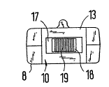
Figure 3 shows that in the vicinity of the grip part 13 at
end 8 of the housing, there can be a recess 17 in the housing
insert. An actuator 18 of a sliding switch can preferably be
movable guided in this recess 17. The actuator 18 can preferably
be provided with a ribbing 19, or some other sort of friction
enhancer, to increase user-friendliness and ease of operation by
forming a substantially non-slip surface on the actuator.
~ NH~-DH-26 CA
2~596~1
Figure 4 is a cross section which illustrates the internal
structure of the housing 5. The slide 1 is shown preferably
mounted and guided within the housing 5 by guide rails 20. In
addition, the slide 1 can be provided with a recess 21 to hold
the specimen. The connecting piece 6 is shown having an internal
thread for engaging an external thread of a shaft piece 22. The
lens system 2 can preferably be engaged with the shaft piece 22,
so that the lens system can essentially be screwed into the con-
necting piece 6. Alternatively, the threaded portions could be
reversed so that the lens system 2 could be screwed externally
about the connecting piece 6.
The shaft 22 preferably has a hole 23 to optically connect
the external lens 15 with an internal lens 24, if an internal
lens is used. By turning the lens system 2 relative to the con-
necting piece 6, the distance between the slide 1 and the lens
system 2 can be changed to thereby perform a focussing of the
enlarged image of the specimen on the slide.
To guide the housing insert 10 into the housing 5, there are
preferably guide elements 26 located within the housing inner
chamber 25. These guide elements 26 preferably extend in the
direction of a longitudinal axis 27 of the housing.
To simplify fabrication of the device, the housing 5 can be
formed from two parts which are connected by means of transverse
webs 28. These transverse webs 28 can be designed, for example,
in the form of bolts, and the end of the webs 28 can be held by
bushing-shaped counter elements 29, which elements 29 could be
threaded for receipt of the bolts, whenever bolts are used.
Figure 5 shows that the housing insert 10 preferably has a
base plate 30 and side walls 31. These side walls 31 can each be
connected to the grip part 13. The base plate 30 can be provided
with a mounting 32 into which an illumination device 3 can be
introduced and retained. The illumination device 3 can be a
NHL~ 6 8 ~
light bulb, for example. There can also be a battery 33 located
within the insert 10 to supply power to the illumination device
3.
To make it possible to turn the illumination device 3 on and
off, the actuator 18 of the sliding switch can be equipped with a
cam 34. By means of the cam 34, a contact 35 can be displaced
upon sliding of the actuator 18. The contact 35 can be elec-
trically connected to one pole of the battery 33 by means of base
contact 36 when the cam 34 is displaced by the actuator 18. When
the cam 34 is moved, the contact 35 can be placed into contact
with a connection contact 37, which connection contact 37 can be
connected to a contact of the illumination device 3. The other
contact of the illumination device 3 can be directly contacting
the opposite pole of the battery 33.
To make possible a secure fastening of the housing insert 10
inside the housing 5, the housing insert preferably has recesses
38 located along the side walls 31. These recesses 38 preferably
engage catches 44 after the housing insert 10 has been inserted a
proper distance into the housing 5.
The housing insert 10 can also preferably have space for
storing additional slides 39. These additional slides 39 can be
oriented essentially parallel to the side walls 31, and can be
protected from slipping by mounting elements 40. To facilitate
the removal of the spare slides 39 from the insert 10, there can
be tapers 41 located in the vicinity of the side walls 31.
One example of an examination procedure for examining saliva
for substances characterizing ovulation phases can be performed
in the following manner. First, a specimen of the saliva is
placed into a recess 21 of a slide l. The slide 1 can then be
laterally inserted into the slot 4 of the housing 5, and the
saliva can then be dried. Alternatively, the saliva could be
dried before the slide is inserted into the housing. After the
NHL-DH-26 CA
2059681
drying process has been completed, which drying process takes
approximately three minutes, the lens system 2 can be turned
relative to the connecting piece 6 to perform a focusing of the
magnified image. The specimen can then be optically examined.
To guarantee sufficient illumination of the specimen, the illu-
mination apparatus 3 can be turned on by means of the actuator
18.
To evaluate the result of the examination, it is necessary
to merely make a determination of whether there are crystalline
structures in the vicinity of the dried saliva specimen. These
crystalline structures would essentially appear as branched crys-
talline structures which resemble the patterns produced by frost
on, for example, an automobile windshield. In the absence of the
substances produced during a woman's fertile period, on the other
hand, punctiform or spotty structures or soap-bubble-like struc-
tures would be formed.
To clean the slide 1 after the examination has been complet-
ed, the slide can be extracted laterally from the housing 5. If
the slide 1 is worn or damaged, it can be replaced by one of the
spare slides 39 stored within housing insert 10.
To make the device according to the present invention porta-
ble, so as to fit in the user's pockets, the overall dimensions
of the device could be, for example, about 110 mm long, about 40
mm wide, and about 20 mm thick. This length of 110mm can include
the length of the lens system 2 which could be, for example about
8 mm. In addition, the diameter of the lens system 2 could be
about 15 mm. The slot 4 into which the slide l is placed can be
located about 2 mm below the upper edge 7 of the housing 5, and
the slot 4 could have cross-sectional dimensions of about 3.5 mm
in height, and about 16 mm in length. The dimensions of the
housing insert 10 could be, for example, about 77 mm long, about
25 mm wide, and about 15 mm thick. Other dimensions, to
accommodate various lens systems, illumination devices, battery
sizes, etc., could also be possible as long as the overall size
of the magnification device was not sufficiently increased so as
to make the device too large to conceal or carry in a pocket.
In general, the device was essentially designed to fit con-
venientLy into an average pocket, such as a shirt pocket or jack-
et pocket, or to fit conveniently into a hand of an average sized
person, so as to make the device portable, unobtrusive, and es-
sentially easy to use.
In summary, one feature of the invention resides broadly in
an apparatus for the optical examination of biological material,
in particular for the examination of a specimen containing sub-
stances which differ as a function of ovulation, characterized by
the fact that in the vicinity of a housing 5 there is an at least
partly transparent slide 1, an illumination apparatus 3 which can
illuminate the slide in an internal housing chamber, and at some
distance from a plane covered by the slide 1, a lens system 2
which optically magnifies the substances located on the slide 1,
and by the fact that the housing S is of a size which allows it
to be carried in the pockets of articles of clothing.
Another feature of the invention resides broadly in an appa-
ratus characterized by the fact that the illumination apparatus 3
is located in the vicinity of a housing insert 10 which can be
inserted into the housing.
Yet another feature of the invention resides broadly in an
apparatus characterized by the fact that the housing insert 10
can be inserted into the housing 5 in the direction of a longi-
tudinal axis 27 of the housing.
A further feature of the invention resides in an apparatus
characterized by the fact that the housing insert 10 is equipped
with a catch which releasably fixes it in an inserted position.
NHL-DH-26 CA
20596gl
Another additional feature of the invention resides broadly
in an apparatus characterized by the fact that the catch is
formed by at least one recess 38, which is located in the vicini-
ty of a side wall 31 of the housing insert 10.
Another additional feature of the invention resides broadly
in an apparatus characterized by the fact that the lens system 2
is equipped with at least one lens which can be oriented at a
variable distance relative to a plane covered by the slide 1.
Another additional feature of the invention resides broadly
in an apparatus characterized by the fact that the lens system 3
has a shaft 22 provided with an external thread, which engages
with an an internal thread of a connecting piece 6.
Another additional feature of the invention resides broadly
in an apparatus characterized by the fact that the slide 1 is
oriented so that it can be inserted laterally into the housing 5.
Another additional feature of the invention resides broadly
in an apparatus characterized by the fact that to guide the hous-
ing insert 10 inside the housing 5, there are guide elements 26
extending in the direction of the longitudinal axis 27 of the
housing.
Another additional feature of the invention resides broadly
in an apparatus characterized by the fact that in the vicinity of
a grip part 13 of the housing insert 10, there is an actuator 18,
pointing downward in the perpendicular direction, as part of a
sliding switch.
Another additional feature of the invention resides broadly
in an apparatus characterized by the fact that in the vicinity of
the housing insert 10 there is at least one spare slide 39.
Another additional feature of the invention resides broadly
in an apparatus characterized by the fact that in the vicinity of
the housing insert lO, there is at least one battery 33 to supply
the illumination apparatus 3.
~ff ~ 5~ 8 ~
All, or substantially all, of the components and methods of
the various embodiments may be used with at least one embodiment
or all of the embodiments, if any, described herein.
The details in the patents, patent applications and publica-
tions may be considered to be incorporable, at applicant's op-
tion, into the claims during prosecution as further limitations
in the claims to patentably distinguish any amended claims from
any applied prior art.
The appended drawings, in their entirety, including all
dimensions, proportions and/or shapes in at least one embodiment
of the invention, are, if applicable, accurate and to scale and
are hereby incorporated by reference into this specification.
The invention as described hereinabove in the context of the
preferred embodiments is not to be taken as limited to all of the
provided details thereof, since modifications and variations
thereof may be made without departing from the spirit and scope
of the invention.