Language selection

Search

Patent 2059710 Summary

Third-party information liability

Some of the information on this Web page has been provided by external sources. The Government of Canada is not responsible for the accuracy, reliability or currency of the information supplied by external sources. Users wishing to rely upon this information should consult directly with the source of the information. Content provided by external sources is not subject to official languages, privacy and accessibility requirements.

Claims and Abstract availability

Any discrepancies in the text and image of the Claims and Abstract are due to differing posting times. Text of the Claims and Abstract are posted:

  • At the time the application is open to public inspection;
  • At the time of issue of the patent (grant).
(12) Patent: (11) CA 2059710
(54) English Title: INTEGRAL PIVOT DAMPER BLADE
(54) French Title: LAME D'AMORTISSEUR A PIVOTEMENT INTEGRAL
Status: Expired and beyond the Period of Reversal
Bibliographic Data
(51) International Patent Classification (IPC):
  • F24F 13/10 (2006.01)
  • B23P 15/00 (2006.01)
(72) Inventors :
  • HEIL, EUGENE J. (United States of America)
(73) Owners :
  • GREENHECK FAN CORPORATION
(71) Applicants :
  • GREENHECK FAN CORPORATION (United States of America)
(74) Agent: SMART & BIGGAR LP
(74) Associate agent:
(45) Issued: 2002-07-02
(22) Filed Date: 1992-01-20
(41) Open to Public Inspection: 1992-09-13
Examination requested: 1998-10-06
Availability of licence: N/A
Dedicated to the Public: N/A
(25) Language of filing: English

Patent Cooperation Treaty (PCT): No

(30) Application Priority Data:
Application No. Country/Territory Date
07/667,875 (United States of America) 1991-03-12

Abstracts

English Abstract


A damper blade is constructed with a laterally
extending, rounded rib and with integral journals on opposite
ends of the rib that form bearing surfaces when the blade is
journaled in openings in the frame of a damper assembly. The
construction provides for convenient manufacturing from a
blank without the addition of hardware for mounting the blade
in a damper assembly.


Claims

Note: Claims are shown in the official language in which they were submitted.

The embodiments of the invention in which an exclusive
property or privilege is claimed are defined as follows:
1. A damper assembly comprising:
a pair of sidewalk spaced apart, the sidewalls having
opposing openings and a damper blade for pivoting movement
around a transverse pivot axis extending between the opposing
openings, the damper blade comprising:
a planar body extending transversely between the
sidewalls for rotation around the transverse pivot axis, the
planar body having top and bottom edges and having sides
extending between the top and bottom edges;
a pair of journals situated along opposite sides of the
planar body, the journals each including a fixed portion
extending along the pivot axis and along the body, and the
journals each including two free end portions extending from
the fixed portion in opposite directions, respectively,
around the pivot axis, to define a respective journal bearing
surface by which a respective side of the damper blade is
supported in a respective one of the openings in the
sidewalls; and
wherein the damper assembly further comprises a pair of
bushings each projecting laterally into an opening in a
respective sidewall, each bushing having a body portion with
an opening situated within the opening in the respective
sidewall for journaled support of a respective journal
bearing surface of the damper blade, and each bushing having
an annular flange disposed inwardly of a respective sidewall
and encircling the opening in the body portion.

2. The damper assembly of claim 1, wherein the damper
blade further comprises:
a rounded rib formed in the body between the top and
bottom edges and extending along the pivot axis, the rounded
rib forming a channel in which the pivot axis is situated
along a center of an arc defined by the rounded rib; and
wherein the fixed portion of each journal is also
rounded and wherein the fixed portion of each journal is an
extension of the rounded rib.
3. The damper assembly of claim 1, wherein the two
portions of each journal are arcuate with inside edges
disposed adjacent to portions of the sides of the damper
blade, the inside edges of the arcuate portions being
separated from the planar body by a slit to allow bending of
the arcuate portions relative to the fixed portion of the
journal.
4. The damper assembly of claim 1, wherein the
bushings are made of nylon.
5. The damper assembly of claim 1, wherein the
sidewalls each include an extrusion formed around a perimeter
of the opening in each respective sidewall to further support
a respective journal bearing surface of the damper blade.
6. The damper assembly of claim 5, wherein the
bushings are made of nylon.
7. A damper assembly comprising:
a pair of sidewalls spaced apart, the sidewalls having
opposing openings and a damper blade for pivoting movement
around a transverse pivot axis extending between the opposing
openings, the damper blade comprising:
-8-

a planar body extending transversely between the
sidewalls for rotation around the transverse pivot axis, the
planar body having top and bottom edges and having sides
extending between the top and bottom edges;
a pair of journals situated along opposite sides of the
planar body, the journals each including a fixed portion
extending along the pivot axis and along the body, and the
journals each including two free end portions extending from
the fixed portion in opposite directions, respectively,
around the pivot axis, to define a respective journal bearing
surface by which a respective side of the damper blade is
supported in a respective one of the openings in the
sidewalls; and
wherein the sidewalls each form an extrusion around a
perimeter of the opening in each respective sidewall to
support a respective journal bearing surface of the damper
blade.
8. The damper assembly of claim 7, further comprising
a pair of bushings each projecting laterally into an opening
in a respective sidewall, each bushing having a body portion
with an opening situated within the opening in the respective
sidewall for journaled support of a respective journal
bearing surface of the damper blade.
9. A method of making a damper blade of the type for a
damper assembly in which a damper frame has sidewalls spaced
apart, and the sidewalls have opposing openings for journaled
support of the damper blade for pivoting movement around a
transverse pivot axis extending between the opposing
openings, the method comprising:
-9-

cutting out a blade having top and bottom edges, having
sides running between the top and bottom edges and having
ears disposed along the sides and along the transverse pivot
axis;
slitting the ears to define a fixed portion and two free
end portions extending from the fixed portion and extending
upwardly and downwardly from the transverse pivot axis; and
bending the free end portions into shape in clockwise
and counterclockwise directions, respectively, around the
pivot axis, to define a respective journal bearing surface by
which a respective side of the damper blade is supported in a
respective one of the openings in the sidewalls.
10. The method of claim 9, further comprising a step of
forming a round rib to extend transversely across the planar
body and through the ears of the blade, wherein the round rib
has a radial centerline that defines the transverse pivot
axis.
-10-

Description

Note: Descriptions are shown in the official language in which they were submitted.


~~e~ a
INTEGRAL PIVOT DAl'4PER BLADE
The field of the invention is damper assemblies that
include a set of damper blades which open and close similar
to blinds or shutters to control the flow of air in heating,
ventilating and air conditioning systems.
Various air flow devices have been proposed with
shutters that open to allow air to escape and which close to
seal and prevent air from escaping at other times.
In typical damper blade designs of the prior art, as
shown in Alley, U.S. Pat. No. 4,887,641 and Myers, No.
4,844,120, each damper blade has a transverse, V-shaped
channel across its middle. A rod of cylindrical or other
shape is clamped in this channel with added hardware, with
the rod acting as the supporting member and the pivot axis
for the damper blade. The ends of the rod extend beyond the
ends of the damper blade and are journaled in holes in the
frame for pivoting the damper blade.
It would be desirable to improve the efficiency of
manufacturing of damper blades and damper blade assemblies
while maintaining or improving performance. To reach these
objectives, the present invention has been made.
The invention is incorporated in a damper blade of the
type for a damper assembly in which a damper frame has
sidewalls spaced apart, and the sidewalls form opposing
openings for journaled support of the damper blade fox
pivoting movement around a transverse pivot axis extending
between the opposing openings.
The damper blade comprises a planar body extending

~l-.ev ~a rc~:.~
~° '~
transversely between the sidewalls for rotation around the
transverse pivot axis. The planar body has top and bottom
edges and has sides extending between the top and bottom
edges. A pair of journals are situated along opposite sides
of the planar body, the journals each including a fixed
portion extending along the pivot axis and along the body,
and the journals each including two free end partions
extending from the fixed portion in opposite directions,
respectively, around the pivot axis, to form a respective
arcuate journal bearing surface.
In a more specific aspect, the invention provides a rib
of semicircular or other cross section, and the jaurnals are
formed in part as extensions of this rib, so that the pivot
axis is positioned in the plane of the blade body.
The construction provides for convenient manufacturing
from a blank without the addition of hardware for mounting
the blade in a damper assembly.
The invention further provides a pair of low-friction
bushings and extrusions formed around openings in the
sidewalk of the damper assembly to support the damper blade
and prolong the life of the journal bearing members. The
integral pivots, low-friction bushings and extrusions provide
an assembly with cost advantages over other designs which
might use heavier gauge material for the damper blade arid
sidewall members.
In the description, reference is made to the
accompanying drawings, which form a part hereof, and which
illustrate examples of the invention. Such examples,
however, are not exhaustive of the various embodiments of the
invention, and therefore reference is made to the claims
-2-

which follow the description for determining the scope of the
invention.
Fig. 1 is a perspective view of a damper assembly which
incorporates the apparatus of the present invention;
Fig. 2 is a side view in elevation with a sidewall
broken away and showing the range of motion between a first
position and a second position shown in phantom;
Fig. 3 is a blank before it is manufactured into the
apparatus seen in Fig. 4; and
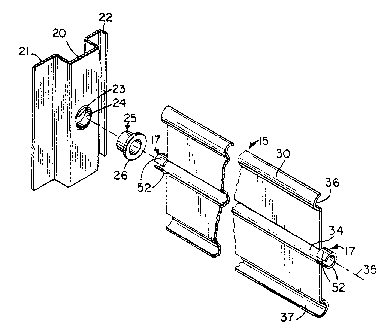
Fig. 4 is an exploded view in perspective of the blade
apparatus of the present invention.
Referring to Fig. 1, a damper assembly 10 includes a
rectangular frame with left and right upright sidewalls 11,
12 spaced apart and connected by a laterally extending top
frame member 13 and a laterally extending bottom frame member
14. A pair of damper blades 15,16 are pivotally mounted to
the frame sidewalls x.1,12 and are in the open positian in
Fig. 1.
As seen best in Fig. 4, each sidewall 11,12 is formed
with a rectilinear channel 20 running from top to bottom
between two flanges 21,22.. A journal opening 23 is formed in
each~channel 20 and encircled by a circular flange 24. A
cylindrical bushing 25 with an annular lip 26 is inserted in
each journal opening to receive a journal 17 of the damper
blade 15,16..
The bushings are made of a low-friction material, such
as nylon. Nylon is the material preferred for lowest cost,
but the bushings 25 can also suitably be made of Derlin'~'~'~
acetal, stainless steel or oil-impregnated bronze.
Each damper blade 15,16 has three round ribs 30,31,32,
-3-

~~~..EY1J 4~ .&~.5
~,-'~ ~~~Y~'S A'.
of semi-circular cross section, which extend transversely
across the blade 15,16. The first round rib 30 extends along
the top edge, the second round rib 31 traverses the blade
midway between the top edge and the bottom edge, and the
third round rib 32 extends along the bottom edge. The second
rib 31 forms a rounded channel 34 in which a pivot axis 35
for the damper blade 15 is situated.
As seen in Figs. 2 and 4, the first rib 30 forms a
channel 36 that opens to the inside of the damper assembly 10
while the other channels 34,37 formed by ribs 31,32 open to
the outside of the damper assembly 10. This allows the first
channel 36 along the top edge of blade 16 to be received in
the third channel 37 of the blade 15 positioned above it.
The pivot axes 35 for the damper blades 15,16 intersect a
substantially vertical centerline for the sidewalls 11,12.
When the blades 15,16 are in the closed position, the first
channel 36 on the top blade l5 abuts an angle flange 39
attached to the top frame member l3 and. the third channel 37
on the bottom blade 16 abuts another angle flange 40 attached
to the bottom frame member 14.
A pair of angle members 41,42 have flanges which are
riveted or otherwise suitably attached to flat portions of
the respective blades 15,16. These members have portions
extending at an acute angle relative to the blades 15,16. The
outside ends of angle members 41,42 are connected by pivot
pins 43,44 to a vertical link 45 which cauples the blades
15,16 together for opening and closing. When the link 45 is
moved outward and downward, 'as illustrated in Fig. 2, the
blades 15,16 are pivoted in a clockwise direction in Fig. 2,
going as far as 90° to an open position.
_4_

~r ~~~
As seen in Fig. 3, a damper blade 15 is advantageously
formed from a blank 46 which is cut from strip stock. The
blank 46 has a rectangular body portion 47 and rectangular
ears 48 located symmetrically relative to a transverse axis
49. Four holes 50 are punched in the ears 48 at
predetermined locations. Then, the ears 48 are slit inwardly
from the top and bottom to the holes 50. The slitting
operation provides fixed portions 51 between holes 50 and
free end portions 52 extending upwardly and downwardly from
holes 50. The blank 46 is then subjected to a forming
operation in which the free end portions 52 are bent around
dowels into arcuate extensions from the fixed portions 50 as
seen in Figs. 2 and 4. This not only results in the integral
formation of journals 17 which are received in the bushings
25 to provide journal bearing surfaces, but in the preferred
form of the damper blade 15, provides a pivot axis 35 at the
radial center of the arc formed by the extensions 52.
Preferably, the center rib 31 is formed with a semi-
circular cross section by a press prior to forming the
journals 17. The fixed portions 51 then also form arcuate
portions of the journals 17. The center rib 31 shapes arid
strengthens the connection of the fixed portions 51 to the
main body 47 of the blade 15. In other embodiments, it may
be possible to form the center rib 31 and the journals 17 in
a single roll forming operation.
This description has been by way o~ example of how the
invention can be carried out. Those with experience in the
art will recognize that various details may be modified in
arriving at other detailed embodiments.
For example, the ears need not project in a transverse
._5-

~I ~~~ ..y ,Lr c .
direction beyond the sides of the blade body 47, as long as
separation is provided between the free end portions 52 and
the blade body 47 to allow the free ends 52 to be bent into
an arcuate shape. In the preferred embodiment the journals
17 are centered around an axis 35 in the plane of the largest
portion of the blade 15, but this is not required in the
broadest aspects of the invention. While the preferred
journals are formed in an arcuate shape, other shapes such as
rectangular or triangular may be employed in alternative
embodiments. And while in the above example, the axis of
rotation and center rib 32 are midway between the top edge
and bottom edge of the blade 15, this is not required in the
broadest aspects of the invention.
Therefore to apprise the public of the scope of the
invention and the embodiments covered by the invention the
following claims are made.

Representative Drawing
A single figure which represents the drawing illustrating the invention.
Administrative Status

2024-08-01:As part of the Next Generation Patents (NGP) transition, the Canadian Patents Database (CPD) now contains a more detailed Event History, which replicates the Event Log of our new back-office solution.

Please note that "Inactive:" events refers to events no longer in use in our new back-office solution.

For a clearer understanding of the status of the application/patent presented on this page, the site Disclaimer , as well as the definitions for Patent , Event History , Maintenance Fee  and Payment History  should be consulted.

Event History

Description Date
Inactive: Reversal of expired status 2012-12-11
Time Limit for Reversal Expired 2012-01-20
Letter Sent 2011-01-20
Grant by Issuance 2002-07-02
Inactive: Cover page published 2002-07-01
Inactive: Final fee received 2002-04-11
Pre-grant 2002-04-11
Notice of Allowance is Issued 2001-12-13
Letter Sent 2001-12-13
Inactive: Approved for allowance (AFA) 2001-12-05
Amendment Received - Voluntary Amendment 1998-12-16
Inactive: Application prosecuted on TS as of Log entry date 1998-10-23
Inactive: RFE acknowledged - Prior art enquiry 1998-10-23
Inactive: Status info is complete as of Log entry date 1998-10-23
All Requirements for Examination Determined Compliant 1998-10-06
Request for Examination Requirements Determined Compliant 1998-10-06
Application Published (Open to Public Inspection) 1992-09-13

Abandonment History

There is no abandonment history.

Maintenance Fee

The last payment was received on 2002-01-02

Note : If the full payment has not been received on or before the date indicated, a further fee may be required which may be one of the following

  • the reinstatement fee;
  • the late payment fee; or
  • additional fee to reverse deemed expiry.

Patent fees are adjusted on the 1st of January every year. The amounts above are the current amounts if received by December 31 of the current year.
Please refer to the CIPO Patent Fees web page to see all current fee amounts.

Owners on Record

Note: Records showing the ownership history in alphabetical order.

Current Owners on Record
GREENHECK FAN CORPORATION
Past Owners on Record
EUGENE J. HEIL
Past Owners that do not appear in the "Owners on Record" listing will appear in other documentation within the application.
Documents

To view selected files, please enter reCAPTCHA code :


To view images, click a link in the Document Description column. To download the documents, select one or more checkboxes in the first column and then click the "Download Selected in PDF format (Zip Archive)" or the "Download Selected as Single PDF" button.

List of published and non-published patent-specific documents on the CPD .

If you have any difficulty accessing content, you can call the Client Service Centre at 1-866-997-1936 or send them an e-mail at CIPO Client Service Centre.


Document
Description 
Date
(yyyy-mm-dd) 
Number of pages   Size of Image (KB) 
Claims 1993-12-12 4 136
Description 1993-12-12 6 215
Drawings 1993-12-12 2 71
Abstract 1993-12-12 1 11
Representative drawing 2002-06-11 1 15
Representative drawing 1999-06-28 1 16
Reminder - Request for Examination 1998-09-21 1 116
Acknowledgement of Request for Examination 1998-10-22 1 172
Commissioner's Notice - Application Found Allowable 2001-12-12 1 166
Maintenance Fee Notice 2011-03-02 1 171
Correspondence 2002-04-10 1 44
Fees 2008-01-17 1 35
Fees 2009-01-15 1 34
Fees 2010-01-17 1 34
Fees 1997-01-09 1 37
Fees 1996-01-10 1 49
Fees 1995-01-12 1 42
Fees 1993-10-20 1 35