Sélection de la langue

Search

Sommaire du brevet 2059710 

Énoncé de désistement de responsabilité concernant l'information provenant de tiers

Une partie des informations de ce site Web a été fournie par des sources externes. Le gouvernement du Canada n'assume aucune responsabilité concernant la précision, l'actualité ou la fiabilité des informations fournies par les sources externes. Les utilisateurs qui désirent employer cette information devraient consulter directement la source des informations. Le contenu fourni par les sources externes n'est pas assujetti aux exigences sur les langues officielles, la protection des renseignements personnels et l'accessibilité.

Disponibilité de l'Abrégé et des Revendications

L'apparition de différences dans le texte et l'image des Revendications et de l'Abrégé dépend du moment auquel le document est publié. Les textes des Revendications et de l'Abrégé sont affichés :

  • lorsque la demande peut être examinée par le public;
  • lorsque le brevet est émis (délivrance).
(12) Brevet: (11) CA 2059710
(54) Titre français: LAME D'AMORTISSEUR A PIVOTEMENT INTEGRAL
(54) Titre anglais: INTEGRAL PIVOT DAMPER BLADE
Statut: Périmé et au-delà du délai pour l’annulation
Données bibliographiques
(51) Classification internationale des brevets (CIB):
  • F24F 13/10 (2006.01)
  • B23P 15/00 (2006.01)
(72) Inventeurs :
  • HEIL, EUGENE J. (Etats-Unis d'Amérique)
(73) Titulaires :
  • GREENHECK FAN CORPORATION
(71) Demandeurs :
  • GREENHECK FAN CORPORATION (Etats-Unis d'Amérique)
(74) Agent: SMART & BIGGAR LP
(74) Co-agent:
(45) Délivré: 2002-07-02
(22) Date de dépôt: 1992-01-20
(41) Mise à la disponibilité du public: 1992-09-13
Requête d'examen: 1998-10-06
Licence disponible: S.O.
Cédé au domaine public: S.O.
(25) Langue des documents déposés: Anglais

Traité de coopération en matière de brevets (PCT): Non

(30) Données de priorité de la demande:
Numéro de la demande Pays / territoire Date
07/667,875 (Etats-Unis d'Amérique) 1991-03-12

Abrégés

Abrégé anglais


A damper blade is constructed with a laterally
extending, rounded rib and with integral journals on opposite
ends of the rib that form bearing surfaces when the blade is
journaled in openings in the frame of a damper assembly. The
construction provides for convenient manufacturing from a
blank without the addition of hardware for mounting the blade
in a damper assembly.

Revendications

Note : Les revendications sont présentées dans la langue officielle dans laquelle elles ont été soumises.


The embodiments of the invention in which an exclusive
property or privilege is claimed are defined as follows:
1. A damper assembly comprising:
a pair of sidewalk spaced apart, the sidewalls having
opposing openings and a damper blade for pivoting movement
around a transverse pivot axis extending between the opposing
openings, the damper blade comprising:
a planar body extending transversely between the
sidewalls for rotation around the transverse pivot axis, the
planar body having top and bottom edges and having sides
extending between the top and bottom edges;
a pair of journals situated along opposite sides of the
planar body, the journals each including a fixed portion
extending along the pivot axis and along the body, and the
journals each including two free end portions extending from
the fixed portion in opposite directions, respectively,
around the pivot axis, to define a respective journal bearing
surface by which a respective side of the damper blade is
supported in a respective one of the openings in the
sidewalls; and
wherein the damper assembly further comprises a pair of
bushings each projecting laterally into an opening in a
respective sidewall, each bushing having a body portion with
an opening situated within the opening in the respective
sidewall for journaled support of a respective journal
bearing surface of the damper blade, and each bushing having
an annular flange disposed inwardly of a respective sidewall
and encircling the opening in the body portion.

2. The damper assembly of claim 1, wherein the damper
blade further comprises:
a rounded rib formed in the body between the top and
bottom edges and extending along the pivot axis, the rounded
rib forming a channel in which the pivot axis is situated
along a center of an arc defined by the rounded rib; and
wherein the fixed portion of each journal is also
rounded and wherein the fixed portion of each journal is an
extension of the rounded rib.
3. The damper assembly of claim 1, wherein the two
portions of each journal are arcuate with inside edges
disposed adjacent to portions of the sides of the damper
blade, the inside edges of the arcuate portions being
separated from the planar body by a slit to allow bending of
the arcuate portions relative to the fixed portion of the
journal.
4. The damper assembly of claim 1, wherein the
bushings are made of nylon.
5. The damper assembly of claim 1, wherein the
sidewalls each include an extrusion formed around a perimeter
of the opening in each respective sidewall to further support
a respective journal bearing surface of the damper blade.
6. The damper assembly of claim 5, wherein the
bushings are made of nylon.
7. A damper assembly comprising:
a pair of sidewalls spaced apart, the sidewalls having
opposing openings and a damper blade for pivoting movement
around a transverse pivot axis extending between the opposing
openings, the damper blade comprising:
-8-

a planar body extending transversely between the
sidewalls for rotation around the transverse pivot axis, the
planar body having top and bottom edges and having sides
extending between the top and bottom edges;
a pair of journals situated along opposite sides of the
planar body, the journals each including a fixed portion
extending along the pivot axis and along the body, and the
journals each including two free end portions extending from
the fixed portion in opposite directions, respectively,
around the pivot axis, to define a respective journal bearing
surface by which a respective side of the damper blade is
supported in a respective one of the openings in the
sidewalls; and
wherein the sidewalls each form an extrusion around a
perimeter of the opening in each respective sidewall to
support a respective journal bearing surface of the damper
blade.
8. The damper assembly of claim 7, further comprising
a pair of bushings each projecting laterally into an opening
in a respective sidewall, each bushing having a body portion
with an opening situated within the opening in the respective
sidewall for journaled support of a respective journal
bearing surface of the damper blade.
9. A method of making a damper blade of the type for a
damper assembly in which a damper frame has sidewalls spaced
apart, and the sidewalls have opposing openings for journaled
support of the damper blade for pivoting movement around a
transverse pivot axis extending between the opposing
openings, the method comprising:
-9-

cutting out a blade having top and bottom edges, having
sides running between the top and bottom edges and having
ears disposed along the sides and along the transverse pivot
axis;
slitting the ears to define a fixed portion and two free
end portions extending from the fixed portion and extending
upwardly and downwardly from the transverse pivot axis; and
bending the free end portions into shape in clockwise
and counterclockwise directions, respectively, around the
pivot axis, to define a respective journal bearing surface by
which a respective side of the damper blade is supported in a
respective one of the openings in the sidewalls.
10. The method of claim 9, further comprising a step of
forming a round rib to extend transversely across the planar
body and through the ears of the blade, wherein the round rib
has a radial centerline that defines the transverse pivot
axis.
-10-

Description

Note : Les descriptions sont présentées dans la langue officielle dans laquelle elles ont été soumises.

~~e~ a
INTEGRAL PIVOT DAl'4PER BLADE
The field of the invention is damper assemblies that
include a set of damper blades which open and close similar
to blinds or shutters to control the flow of air in heating,
ventilating and air conditioning systems.
Various air flow devices have been proposed with
shutters that open to allow air to escape and which close to
seal and prevent air from escaping at other times.
In typical damper blade designs of the prior art, as
shown in Alley, U.S. Pat. No. 4,887,641 and Myers, No.
4,844,120, each damper blade has a transverse, V-shaped
channel across its middle. A rod of cylindrical or other
shape is clamped in this channel with added hardware, with
the rod acting as the supporting member and the pivot axis
for the damper blade. The ends of the rod extend beyond the
ends of the damper blade and are journaled in holes in the
frame for pivoting the damper blade.
It would be desirable to improve the efficiency of
manufacturing of damper blades and damper blade assemblies
while maintaining or improving performance. To reach these
objectives, the present invention has been made.
The invention is incorporated in a damper blade of the
type for a damper assembly in which a damper frame has
sidewalls spaced apart, and the sidewalls form opposing
openings for journaled support of the damper blade fox
pivoting movement around a transverse pivot axis extending
between the opposing openings.
The damper blade comprises a planar body extending

~l-.ev ~a rc~:.~
~° '~
transversely between the sidewalls for rotation around the
transverse pivot axis. The planar body has top and bottom
edges and has sides extending between the top and bottom
edges. A pair of journals are situated along opposite sides
of the planar body, the journals each including a fixed
portion extending along the pivot axis and along the body,
and the journals each including two free end partions
extending from the fixed portion in opposite directions,
respectively, around the pivot axis, to form a respective
arcuate journal bearing surface.
In a more specific aspect, the invention provides a rib
of semicircular or other cross section, and the jaurnals are
formed in part as extensions of this rib, so that the pivot
axis is positioned in the plane of the blade body.
The construction provides for convenient manufacturing
from a blank without the addition of hardware for mounting
the blade in a damper assembly.
The invention further provides a pair of low-friction
bushings and extrusions formed around openings in the
sidewalk of the damper assembly to support the damper blade
and prolong the life of the journal bearing members. The
integral pivots, low-friction bushings and extrusions provide
an assembly with cost advantages over other designs which
might use heavier gauge material for the damper blade arid
sidewall members.
In the description, reference is made to the
accompanying drawings, which form a part hereof, and which
illustrate examples of the invention. Such examples,
however, are not exhaustive of the various embodiments of the
invention, and therefore reference is made to the claims
-2-

which follow the description for determining the scope of the
invention.
Fig. 1 is a perspective view of a damper assembly which
incorporates the apparatus of the present invention;
Fig. 2 is a side view in elevation with a sidewall
broken away and showing the range of motion between a first
position and a second position shown in phantom;
Fig. 3 is a blank before it is manufactured into the
apparatus seen in Fig. 4; and
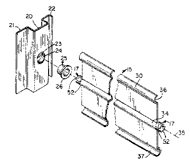
Fig. 4 is an exploded view in perspective of the blade
apparatus of the present invention.
Referring to Fig. 1, a damper assembly 10 includes a
rectangular frame with left and right upright sidewalls 11,
12 spaced apart and connected by a laterally extending top
frame member 13 and a laterally extending bottom frame member
14. A pair of damper blades 15,16 are pivotally mounted to
the frame sidewalls x.1,12 and are in the open positian in
Fig. 1.
As seen best in Fig. 4, each sidewall 11,12 is formed
with a rectilinear channel 20 running from top to bottom
between two flanges 21,22.. A journal opening 23 is formed in
each~channel 20 and encircled by a circular flange 24. A
cylindrical bushing 25 with an annular lip 26 is inserted in
each journal opening to receive a journal 17 of the damper
blade 15,16..
The bushings are made of a low-friction material, such
as nylon. Nylon is the material preferred for lowest cost,
but the bushings 25 can also suitably be made of Derlin'~'~'~
acetal, stainless steel or oil-impregnated bronze.
Each damper blade 15,16 has three round ribs 30,31,32,
-3-

~~~..EY1J 4~ .&~.5
~,-'~ ~~~Y~'S A'.
of semi-circular cross section, which extend transversely
across the blade 15,16. The first round rib 30 extends along
the top edge, the second round rib 31 traverses the blade
midway between the top edge and the bottom edge, and the
third round rib 32 extends along the bottom edge. The second
rib 31 forms a rounded channel 34 in which a pivot axis 35
for the damper blade 15 is situated.
As seen in Figs. 2 and 4, the first rib 30 forms a
channel 36 that opens to the inside of the damper assembly 10
while the other channels 34,37 formed by ribs 31,32 open to
the outside of the damper assembly 10. This allows the first
channel 36 along the top edge of blade 16 to be received in
the third channel 37 of the blade 15 positioned above it.
The pivot axes 35 for the damper blades 15,16 intersect a
substantially vertical centerline for the sidewalls 11,12.
When the blades 15,16 are in the closed position, the first
channel 36 on the top blade l5 abuts an angle flange 39
attached to the top frame member l3 and. the third channel 37
on the bottom blade 16 abuts another angle flange 40 attached
to the bottom frame member 14.
A pair of angle members 41,42 have flanges which are
riveted or otherwise suitably attached to flat portions of
the respective blades 15,16. These members have portions
extending at an acute angle relative to the blades 15,16. The
outside ends of angle members 41,42 are connected by pivot
pins 43,44 to a vertical link 45 which cauples the blades
15,16 together for opening and closing. When the link 45 is
moved outward and downward, 'as illustrated in Fig. 2, the
blades 15,16 are pivoted in a clockwise direction in Fig. 2,
going as far as 90° to an open position.
_4_

~r ~~~
As seen in Fig. 3, a damper blade 15 is advantageously
formed from a blank 46 which is cut from strip stock. The
blank 46 has a rectangular body portion 47 and rectangular
ears 48 located symmetrically relative to a transverse axis
49. Four holes 50 are punched in the ears 48 at
predetermined locations. Then, the ears 48 are slit inwardly
from the top and bottom to the holes 50. The slitting
operation provides fixed portions 51 between holes 50 and
free end portions 52 extending upwardly and downwardly from
holes 50. The blank 46 is then subjected to a forming
operation in which the free end portions 52 are bent around
dowels into arcuate extensions from the fixed portions 50 as
seen in Figs. 2 and 4. This not only results in the integral
formation of journals 17 which are received in the bushings
25 to provide journal bearing surfaces, but in the preferred
form of the damper blade 15, provides a pivot axis 35 at the
radial center of the arc formed by the extensions 52.
Preferably, the center rib 31 is formed with a semi-
circular cross section by a press prior to forming the
journals 17. The fixed portions 51 then also form arcuate
portions of the journals 17. The center rib 31 shapes arid
strengthens the connection of the fixed portions 51 to the
main body 47 of the blade 15. In other embodiments, it may
be possible to form the center rib 31 and the journals 17 in
a single roll forming operation.
This description has been by way o~ example of how the
invention can be carried out. Those with experience in the
art will recognize that various details may be modified in
arriving at other detailed embodiments.
For example, the ears need not project in a transverse
._5-

~I ~~~ ..y ,Lr c .
direction beyond the sides of the blade body 47, as long as
separation is provided between the free end portions 52 and
the blade body 47 to allow the free ends 52 to be bent into
an arcuate shape. In the preferred embodiment the journals
17 are centered around an axis 35 in the plane of the largest
portion of the blade 15, but this is not required in the
broadest aspects of the invention. While the preferred
journals are formed in an arcuate shape, other shapes such as
rectangular or triangular may be employed in alternative
embodiments. And while in the above example, the axis of
rotation and center rib 32 are midway between the top edge
and bottom edge of the blade 15, this is not required in the
broadest aspects of the invention.
Therefore to apprise the public of the scope of the
invention and the embodiments covered by the invention the
following claims are made.

Dessin représentatif
Une figure unique qui représente un dessin illustrant l'invention.
États administratifs

2024-08-01 : Dans le cadre de la transition vers les Brevets de nouvelle génération (BNG), la base de données sur les brevets canadiens (BDBC) contient désormais un Historique d'événement plus détaillé, qui reproduit le Journal des événements de notre nouvelle solution interne.

Veuillez noter que les événements débutant par « Inactive : » se réfèrent à des événements qui ne sont plus utilisés dans notre nouvelle solution interne.

Pour une meilleure compréhension de l'état de la demande ou brevet qui figure sur cette page, la rubrique Mise en garde , et les descriptions de Brevet , Historique d'événement , Taxes périodiques et Historique des paiements devraient être consultées.

Historique d'événement

Description Date
Inactive : Renversement de l'état périmé 2012-12-11
Le délai pour l'annulation est expiré 2012-01-20
Lettre envoyée 2011-01-20
Accordé par délivrance 2002-07-02
Inactive : Page couverture publiée 2002-07-01
Inactive : Taxe finale reçue 2002-04-11
Préoctroi 2002-04-11
Un avis d'acceptation est envoyé 2001-12-13
Lettre envoyée 2001-12-13
Inactive : Approuvée aux fins d'acceptation (AFA) 2001-12-05
Modification reçue - modification volontaire 1998-12-16
Inactive : Dem. traitée sur TS dès date d'ent. journal 1998-10-23
Inactive : Acc. réc. RE - Pas de dem. doc. d'antériorité 1998-10-23
Inactive : Renseign. sur l'état - Complets dès date d'ent. journ. 1998-10-23
Toutes les exigences pour l'examen - jugée conforme 1998-10-06
Exigences pour une requête d'examen - jugée conforme 1998-10-06
Demande publiée (accessible au public) 1992-09-13

Historique d'abandonnement

Il n'y a pas d'historique d'abandonnement

Taxes périodiques

Le dernier paiement a été reçu le 2002-01-02

Avis : Si le paiement en totalité n'a pas été reçu au plus tard à la date indiquée, une taxe supplémentaire peut être imposée, soit une des taxes suivantes :

  • taxe de rétablissement ;
  • taxe pour paiement en souffrance ; ou
  • taxe additionnelle pour le renversement d'une péremption réputée.

Les taxes sur les brevets sont ajustées au 1er janvier de chaque année. Les montants ci-dessus sont les montants actuels s'ils sont reçus au plus tard le 31 décembre de l'année en cours.
Veuillez vous référer à la page web des taxes sur les brevets de l'OPIC pour voir tous les montants actuels des taxes.

Historique des taxes

Type de taxes Anniversaire Échéance Date payée
TM (demande, 6e anniv.) - générale 06 1998-01-20 1998-01-20
Requête d'examen - générale 1998-10-06
TM (demande, 7e anniv.) - générale 07 1999-01-20 1999-01-11
TM (demande, 8e anniv.) - générale 08 2000-01-20 2000-01-11
TM (demande, 9e anniv.) - générale 09 2001-01-22 2000-10-31
TM (demande, 10e anniv.) - générale 10 2002-01-21 2002-01-02
Taxe finale - générale 2002-04-11
TM (brevet, 11e anniv.) - générale 2003-01-20 2002-12-24
TM (brevet, 12e anniv.) - générale 2004-01-20 2004-01-15
TM (brevet, 13e anniv.) - générale 2005-01-20 2004-10-26
TM (brevet, 14e anniv.) - générale 2006-01-20 2005-10-20
TM (brevet, 15e anniv.) - générale 2007-01-22 2007-01-04
TM (brevet, 16e anniv.) - générale 2008-01-21 2008-01-18
TM (brevet, 17e anniv.) - générale 2009-01-20 2009-01-16
TM (brevet, 18e anniv.) - générale 2010-01-20 2010-01-18
Titulaires au dossier

Les titulaires actuels et antérieures au dossier sont affichés en ordre alphabétique.

Titulaires actuels au dossier
GREENHECK FAN CORPORATION
Titulaires antérieures au dossier
EUGENE J. HEIL
Les propriétaires antérieurs qui ne figurent pas dans la liste des « Propriétaires au dossier » apparaîtront dans d'autres documents au dossier.
Documents

Pour visionner les fichiers sélectionnés, entrer le code reCAPTCHA :


Pour visualiser une image, cliquer sur un lien dans la colonne description du document. Pour télécharger l'image (les images), cliquer l'une ou plusieurs cases à cocher dans la première colonne et ensuite cliquer sur le bouton "Télécharger sélection en format PDF (archive Zip)" ou le bouton "Télécharger sélection (en un fichier PDF fusionné)".

Liste des documents de brevet publiés et non publiés sur la BDBC .

Si vous avez des difficultés à accéder au contenu, veuillez communiquer avec le Centre de services à la clientèle au 1-866-997-1936, ou envoyer un courriel au Centre de service à la clientèle de l'OPIC.


Description du
Document 
Date
(aaaa-mm-jj) 
Nombre de pages   Taille de l'image (Ko) 
Revendications 1993-12-12 4 136
Description 1993-12-12 6 215
Dessins 1993-12-12 2 71
Abrégé 1993-12-12 1 11
Dessin représentatif 2002-06-11 1 15
Dessin représentatif 1999-06-28 1 16
Rappel - requête d'examen 1998-09-21 1 116
Accusé de réception de la requête d'examen 1998-10-22 1 172
Avis du commissaire - Demande jugée acceptable 2001-12-12 1 166
Avis concernant la taxe de maintien 2011-03-02 1 171
Correspondance 2002-04-10 1 44
Taxes 2008-01-17 1 35
Taxes 2009-01-15 1 34
Taxes 2010-01-17 1 34
Taxes 1997-01-09 1 37
Taxes 1996-01-10 1 49
Taxes 1995-01-12 1 42
Taxes 1993-10-20 1 35