Note: Descriptions are shown in the official language in which they were submitted.
CA 02059717 2002-09-23
1
RAILROAD TIE
Technical Field
The technical field of this invention relates to railroad ties with provisions
for reducing lengthwise movement thereof within railroad bed ballast.
Background Art
There has always been a need in the railroad industry for ties with provisions
to maximize resistance to motion along the tie length dimension. Such motion
occurs in response to forces applied by weather conditions, and by the passage
of
trains along the rails. The problem of "tie movement" is most realized in
areas
where the rails curve. The rails in such areas are subjected to substantial
lateral
forces from the trains moving around the turns. Ties are also additionally
subjected
to forces applied by the rails themselves as they expand and contract in cold
and
warm weather conditions. The problem is amplified with the new "ribbon" rails
that extend for substantial distances without joints.
IS One solution to the problem of lateral track movement is the provision for
more railroad ties and closer spacing in areas where the track curves. This is
not
economically effective as railroad ties are becoming increasingly expensive.
The above problem is addressed in U.S. Patent No. 1,888,287 issued on
November 22, 1932 to Prot which discloses a "ferro-concrete railway sleeper".
The
ZO configuration of the tie includes an enlarged foot used to distribute
vertical loading
and minimize pressure on the ground surface. The tie is hollow along its
length and
includes a substantially rectangular central cross section adjacent the areas
between
rail mounting surfaces thereof. Webbing is provided at the rail mounting
surfaces
extending angularly downward from the rail mounting surfaces to the widened
foot.
25 Resistance to "side stresses" is claimed to be increased by provision of
diverging
ribs provided at the end portions of the sleeper.
Another attempted solution to the above problem is found in U.S. Patent No.
1,720,473 issued on July 9, 1929 to Habicht which discloses a railroad tie
with a
specific configuration intended to hold position within ballast. This tie
construction
3o includes a substantially triangular cross sectional configuration in which
the top,
flat surface of the tie represents one side of the triangular cross sectional
CA 02059717 2002-09-23
2
configuration. Thus, the side walls converge downwardly in areas of the tie
with
the exception of those areas mounting the rails. It is stated that this form
of tie
configuration will afford a more uniform distribution of load on the
surrounding
ballast and will retain its position within the ballast.
U.S. Patent No. 530,778 issued on December 1 l, 1894 to Ingersoll discloses
a tie configuration that is approximately opposite in cross sectional
configuration to
the Habicht reference discussed above. Here, end and central side surfaces of
the
tie diverge from the top surface to an enlarged foot at the bottom portion of
the tie.
Again, this configuration is claimed to effectively prevent endwise movement
of
I D the ties.
While the above ties may indeed improve traction and distribution of load, it
remains desirable to obtain maximum resistance to lateral tie movement,
especially
when ties are used in conjunction with elongated, seamless "ribbon" rails. In
doing
so, it is desirable to obtain maximum traction of such ties within the
aggregate
forming the roadbed. Thus, it is the primary objective of the present
invention to
provide a tie configuration of economically feasible construction and that
will
provide maximum grip within a prepared aggregate ballast.
Accordingly, one aspect of the present invention resides in a concrete
railroad tie for placement in ballast with aggregate having a maximum
dimension,
comprising an elongated tie body defining a longitudinal axis along its major
length, said tie body including a longitudinal top surface for placement of a
railway
rail thereon, a bottom surface, and two opposed side surfaces extending
between
opposed transverse ends; said tie body including a plurality of ballast
locking
indentations formed therein along the two opposed side surfaces, each
indentation
extending between the top surface and the bottom surface, each indentation
converging downwardly from an enlarged top end having an enlarged width
dimension measured along the longitudinal axis to a reduced bottom end having
a
reduced width dimension measured along the longitudinal axis, said reduced
bottom end extending to and opening at the bottom surface of the tie body,
said
enlarged top end extending to and opening at the top surface of the tie body,
said
reduced width being substantially equal to the maximum size dimension
aggregate.
CA 02059717 2002-09-23
2a
In another aspect, the present invention resides in a concrete railroad tie
for
placement in ballast with aggregate having a maximum dimension, comprising an
elongated tie body defining a longitudinal axis along its major length, said
body
including a longitudinal top surface for placement of a railway rail thereon,
a
bottom surface, and two opposed side surfaces extending between opposed
transverse ends said tie body including a plurality of ballast locking
indentations
formed therein along the two opposed side surfaces, each indentation extending
between the top surface and the bottom surface, each indentation converging
downwardly from an enlarged top end having an enlarged width dimension
measured along the longitudinal axis to a reduced bottom end having a reduced
width dimension measured along the longitudinal axis, said reduced width being
substantially equal to the maximum size dimension aggregate; and each
indentation
including a depth dimension measurable inwardly into the tie body from the
side
surface, said depth dimension tapering from a maximum dimension at the reduced
bottom end to a minimum dimension at the enlarged top end.
Brief Description of the Drawings
Fig. 1 is a frontal elevation view of a railroad tie according to principles
of
the present invention;
Fig. 2 is a top plan view of the present preferred tie configuration;
2o Fig. 3 is a bottom plan view of the present tie;
Fig. 4 is an enlarged sectional view taken substantially along line 4-4 in
Fig. 2;
Fig. S is an enlarged cross sectional view taken substantially along line S-S
in
Fig. 2;
Fig. 6 is a perspective view of the present tie configuration; and
Fig. 7 is a fragmented diagrammatic view illustrating placement of a portion
of the present tie configuration in ballast.
Best Modes for Carrying Out the Invention
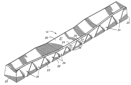
A preferred form of the present tie is generally indicated in the drawings by
the reference character 10. The present tie 10 is intended to be placed within
screened or otherwise graded ballast 11 made up of various sized aggregate 12.
In
CA 02059717 2002-09-23
2b
accordance with standard practice, such ballast include an aggregate up to a
size of
approximately 2.50 inches (6.35 cm). Such ballast is typically gravel and
stone that
has been screened or otherwise graded and is carefully placed in preparation
for
receiving ties and rails. The use of aggregate
~~59'~~'~
CX1.002. P01
and ballast and the placement of such ballast is well known to the railroad
industry and need not be discussed in further detail herein. It is sufficient
to
note that the typical maximum aggregate size at khe roadbed level and within
the ballast area for a standard tie configurations is the 2.50 (6.35 cm)
inches
s cited above.
For purposes of illustration, a portion of railroad ballast 11 is shown in
Fig. 7 of the drawings. It is pointed out that the showing is merely exemplary
of approximate aggregate size and is not intended to show actual ballast
layering,
composition, etc.
lo The present tie 10 is comprised of an elongated tie body 20. The tie
body, in the preferred form, is constructed of reinforced concrete, cast by
conventionally known techniques. It has been found that reinforced concrete is
advantageously used due to the unique configuration of the present tie 10, and
for the strength and reliability of the reinforced concrete product.
Is The tie body 20 includes a longitudinal top surface 21 and a substantially
parallel opposed bottom surface 22. The top surface 21 may be stepped as
indicated in Fig. 1, or may take other configurations where appropriate. The
bottom surface 22 likewise may be substantially flat as indicated, or may be
provided with textured configurations as desired.
2o The top and bottom surfaces 21, 22 extend the full length of the tie
body and are separated by longitudinal side surfaces 23. The side surfaces 23
are, in the preferred form, divergent from the top surface 21 to the bottom
surface 22. A bevel 24 joins the top surface 21 and the side surfaces 23 in
the preferred configuration. The tie top surface 21, bottom surface 22, and
side
2s surfaces 23 all extend the length of the tie between opposed transverse end
surfaces 25.
In the preferred configuration, reinforcing rods 28 are provided within the
tie adjacent to the opposed side surfaces 23. The rods 28 are placed according
to conventional technique known in the art of concrete tie construction.
3o An important aspect of the present invention is the provision of the
number of ballast locking indentations 34 along the side surfaces 23. It is
pointed out that thexe are a plurality of the indentations formed along the
full
length of each side surface 23. The indentations provide the capability along
the full length of the tie exposed to the ballast aggregate 12, for
interlocking
a 2 p ~ ~~.~~~
with the aggregate 1'1 and therefore providing substantial resistance to
movement
along the tie length.
The individual indentations are substantially identical, or at least have
similar characteristics, one to the other along the opposite sides of the tie.
Each indentation 34 includes a longitudinally enlarged top end 3S that, in
a preferred form, is open along the top surface 21. The indentation then
tapers
downwardly to a reduced bottom end 36. In the preferred form, the reduced
bottom ends 36 open along the bottom surface 22. Thus, each indentation 34
has a somewhat funnel configuration, formed into the side surface of the tie
1o body. The funnel configurations are partially defined between converging
indention side edges 37, and the exposed side surfaces of the tie between the
edges 37, the top ends 35, and the bottom ends 36.
The indentations include a depth dimension identified by numeral 38 in
Fig. 4. The depth dimension tapers from a maximum depth dimension 38 of
approximately 0.50 inches (1.27 cm) or, more preferably, about 0.56 inches
(1.42 cm). The depth dimension 38 in the preferred form occurs at the bottom
ends 36 of the indentations.
The depth dimension 38 decreases toward the top surface 21 as indicated
in Figs. 4 and 5, and as may be seen in the perspective view of Fig. 6 where
2o the depth dimension is less than 0.50 inches (1.27 cm). This configuration
contributes to a ballast interlocking effect between the tie and the
surrounding
ballast aggregate.
Another dimension, measured along the length of the tie along each of
the ballast locking indentations at its open bottom end 36 is shown in Fig. 2
by the reference numeral 39. This dimension 39, in the preferred form, is
intended to match or correspond substantially with the largest aggregate size
used
in the ballast 11. Thus, in the preferred form, the dimension 39 is
approximately 2.50 inches (6.35 cm). Indentation edges 37 diverge upwardly
from
the ends 36 to open top ends 35 having dimensions along the length of the tie
3o that are substantially greater than 2.50 inches (6.35 cm).
The dimensions 38, 39 of the indentations exemplified above are selected
to correspond substantially with the ballast being used in the road bed, and
may
vary accordingly. However, the funnel configurations will consistently be
shaped
such that settling ballast will become gradually and more firmly interlocked
with
the various indentations along the length of the tie. This feature has been
CXI-'002.POt
found to very substantially increase the resistance to longitudinal movement
of
the tie (with respect to its length) in ballast situations.
in practice, the present tie is placed within the ballast using known,
conventional placement techniques. In fact, the present tie may be placed
using
s all previously used placement techniques and tamping considerations as have
been
used in conventional track building practices. The advantage of the present
tie's
capability to resist movement along its length with the ballast is realized
through
the particular configurations described above such that the tie becomes
substantially interlocked with the aggregate surrounding the tie. The settling
1o aggregate will, in the vicinity of the various indentations, engage the
converging
side surfaces of the indentation and consolidate as they settle downwardly.
The
aggregate therefore gradually becomes wedged within the various indentations,
and
with one another to thereby become relatively integral. This situation leads
to
a dramatic resistance to lateral movement by the tie as applied either by
testing
1s equipment, or by rails in actual practice.
The present tie includes the further advantage in that the amount of
materials used to construct the present tie is equal to or less than that
required
far conventional tie configurations.