Note: Descriptions are shown in the official language in which they were submitted.
205976~
METHOD OF ATTACHING A HAPTIC TO AN OPTIC
OF AN INTRAOCULAR LENS
Background of the Invention
The present invention relates to intraocular lenses, particularly to
5 methods for attaching a haptic to an optic using laser welding.
Intraocular lenses have been known since about 1950. They are used
to replace the natural lenses of eyes which have been damaged by trauma or
disease, such as cataracts. A typical intraocular lens (IOL) comprises an
artificial lens ("optic") and at least one support member ("haptic") for
positioning the IOL in the eye. The optic may be formed from any of a
number of different materials, including polymethylmethacrylate (PMMA), and
it may be hard, relatively flexible or even fully deformable in order to
permit the IOL to be rolled or folded and inserted through a relatively
small incision in the eye. The haptic is generally made of some resilient
material, such as polypropylene or PMMA. IOL's may be characterized as
either "one-piece" or "multi-piece." In the one-piece IOL's, the haptic
and the optic are integrally formed and the IOL is then cut to the desired
shape and configuration. The multi-piece IOL's are formed either by
attaching the haptic to a pre-formed optic or by molding the optic around
20 an end portion of the haptic.
U.S. Patents Nos. 4,834,751 and 4,894,062 (both Knight, et al.)
describe haptic attachment methods whereby a haptic and an anchoring member
are joined, then an optic is molded around the end portion of the haptic
having the anchoring member joined. While these methods provide strong
25 haptic-optic interlock, the procedure for molding an optic around
previously joined haptic and anchor members is complex and requires special
20597S4
care to maintain the haptic in place while the optic material is being
cured and to remove the mold without damaging the haptic.
Many methods for attaching a haptic to a pre-formed optic are known,
including those involving the use of adhesives. If an adhesive is used to
5 attach a haptic to an optic, the adhesive must be strong, biologically
inert and resistant to degradation by bodily fluids. At present, there are
few materials which would satisfy all these requirements. In addition,
there is a danger that the adhesive would deteriorate over time, resulting
in loose or detached haptics within the eye.
Other, more common, methods for attaching a haptic to a pre-formed
optic involve the use of heat. One such haptic attachment method involves
drilling intersecting holes into the periphery of an optic and inserting
one end of the haptic into one of the holes. A heated probe is then
inserted through the other hole, contacting the haptic and causing a
15 portion of it to melt into the second hole. When the haptic end portion
hardens, a mechanical interlock with the optic is formed. A similar method
is disclosed in U.S. Patent No. 4,104,339 (Fetz, et al.), where a haptic
hole is made in the peripheral edge of an optic, the haptic end is inserted
into the hole and then an inductively heated thin probe is pushed through
20 the posterior face of the optic into contact with the haptic end to form a
fused connection between the haptic and the optic. This is currently the
most common method for attaching a haptic to an optic.
Another such method is disclosed in U.S. Patent No. 4,307,043 (Chase,
et al.), where a hole having threaded recesses is made through a portion of
25 the optic (the hole being essentially parallel to the plane of the optic)
and one end of a haptic is inserted through the hole so that it projects
beyond the optic. Heat is then applied to the haptic end projecting beyond
- ` ~059764
the optic to melt a portion of it, which fills the threaded portions of the
hole. When the haptic material hardens, a mechanical interlock with the
optic is formed.
These heat attachment techniques described above are disadvantageous
s in that skilled technicians are required and/or there is danger of damage
- to the optic.
U.S. Patent No. 4,786,445 (Portnoy, et al.) discloses another haptic
attachment method which involves making a cavity in the periphery of an
optic, wherein the innermost portion of the cavity has a shoulder. A
o haptic end portion is inserted into the cavity and laser energy of a near
infrared wavelength is transmitted through the optic to the haptic, causing
it to melt and flow into the shoulder of the cavity. When the end portion
hardens, a mechanical interlock between the haptic and the optic is formed.
Although this method avoids some of the problems of the prior-mentioned
15 methods, there are other disadvantages. Because the haptic end is melted
to form a shoulder within the cavity of the optic, there is a likelihood of
variation in haptic length, both between individual IOL's and between
individual haptics attached to the same IOL.
Summary of the Invention
This invention is directed to methods for attaching a haptic to an
optic without damaging the optic while producing a strong mechanical
interlock between the haptic and the optic. This is accomplished by
forming two separate, intersecting holes within the periphery of an optic,
inserting the end portion of a haptic into one hole, inserting an anchor
strand into the second hole so that the two strands intersect and
20597~ ~
transmitting laser energy of a visible wavelength through the optic to the
intersection of the two strands, whereby the anchor strand and the haptic
end portion are fused, forming a solid junction and mechanically anchoring
the haptic within the optic. Use of a laser transmitting energy in the
s visible region of the spectrum is less hazardous than use of other forms of
laser energy since the laser beam is easily seen and thus more readily
avoided.
Brief Description of the Drawing
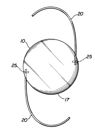
Figure 1 is an elevational view of a typical IOL made in accordance
with the methods of the present invention.
Figure 2 is a side elevation view of a typical IOL, such as shown in
Figure 1, made in accordance with the methods of the present invention.
Figures 3, 4, and 5 are fragmentary sectional views of optics,
showing alternative hole configurations for attaching haptics in accordance
15 with the methods of the present invention.
Figures 6, 7, and 8 are fragmentary sectional views of a typical
optic, showing holes for attaching haptics.
Figures 9, 10, and 11 are elevational views of IOL's, showing
alternative haptic configurations, wherein the haptics are attached in
20 accordance with the methods of the present invention.
Detailed Description of the Invention
A typical IOL, shown in Figures 1 and 2, includes an optic 10 and two
identical haptics 20. The haptics 20 may be configured in any of a number
205~76~
of ways and the optic 10 may have any of a number of shapes. The optic
shape and haptic configuration shown in Figures 1 and 2 are illustrative
only and are not meant to be limiting.
As shown in Figure 2, the optic 10 has an anterior face 13, a
posterior face 15 and a peripheral edge 17. The optic may be made of any
of a number of known materials, including, but not limited to: PMMA and
soft acrylics, silicones, or hydrogels. Preferred optic materials are the
high refractive index copolymers disclosed in co-pending, commonly
assigned, U.S. Patent Application SN 07/609,836 filed on November 7, 1990.
o The haptics 20 are formed separately from the optic 10 and then
attached along a portion of the peripheral edge 17. At least the haptic
end portion to be attached to the optic must comprise non-transparent or
colored material which is capable of absorbing visible wavelength laser
energy. The haptics may be made of any of a number of resilient polymeric
materials including, but not limited to: PMMA, polypropylene, polyimides
and polyvinylidene difluoride. The haptic material may either be different
from or the same as the optic material. Haptic material which is
transparent and non-colored must either include a dye or be combined with a
colored material, such as by using a colored core. The preferred haptic
materials are PMMA with a copper phthalocyanine-doped core and blue
propylene.
The anchor strand which is joined to the haptic end portion in the
optic must also comprise a non-transparent or colored material capable of
absorbing visible wavelength laser energy and may be made of any haptic
material. The anchor strand and haptic end portion must be made of
materials capable of fusing to one another, preferably the same material.
The anchor strand may be either: a short strand of haptic material which,
20!~976~
when attached, will fit completely within the second hole of the optic; a
long strand of haptic material which is severed at the optic periphery
after the haptic end portion has been joined to it; or the other end
portion of the haptic.
If loop haptic configurations are desired, each end of a haptic will
be attached to the optic. For example, Figure 9 illustrates a loop
configuration wherein each end of a haptic is attached by a set of
intersecting holes. Figures 10 and 11 illustrate alternative loop
configurations where the second end of the haptic is the anchor strand.
The laser used to weld the haptic to the optic is one capable of
transmitting energy in the visible region of the spectrum, approximately
450 to 750 nanometers (nm). Visible wavelength laser energy will be at
least partially absorbed by the non-transparent or colored haptic material,
regardless of the specific wavelength of energy used; however, it is
preferable that the laser energy used is coordinated with the color of the
haptic to be attached. For example, if a blue haptic is to be attached,
laser energy having a wavelength in the blue portion of the visible
spectrum is preferred. An Argon laser capable of transmitting energy
between about 450 and about 550 nm is preferred.
The intersecting holes in the optic may be made in any suitable
manner and be made either after the optic has been formed or the optic may
be formed with pre-formed holes. As shown in Figures 3, 4, 5 and 8, the
holes may end at the point of intersection (the embodiments shown in
Figures 3 and 4), or one or both holes may extend beyond the intersection
(the embodiments shown in Figures 5 and 8). It is preferred that the
intersecting holes are perpendicular to one another and that at least one
hole extends beyond the intersection. It is most preferred that the
- 205976~
intersecting holes are perpendicular to one another and that both holes
extend beyond the intersection.
To attach a haptic to an optic having intersecting holes, one end of
a haptic is inserted fully into the first hole and one end of an anchor
strand is inserted into the second hole so that the anchor strand and
haptic intersect. A laser capable of generating energy of a visible
wavelength is then aimed at the intersection of the first and second holes
and the laser is fired to fuse the anchor strand and the haptic at their
point of intersection.
The following is an example of a method of the present invention,
wherein the optic is made of a soft material, such as the high refractive
index copolymers disclosed in U.S. Patent Application Serial No.
07/609,836. Reference numerals refer to Figures 1, 2 and 6 through 8.
EXAMPLE
The haptic 20 is inserted fully into hole 303 and is inserted into
hole 304 to the point where the optic 10 distorts, as shown in Figure 6. A
laser is then aimed and fired at point A. While firing, the laser is moved
back and forth in the direction of the arrows shown in Figure 6 until the
optic relaxes, as shown in Figure 7. The process of feeding the haptic
anchor 25 into the anchor hole 304 and then firing the laser at point A is
repeated as many times as necessary until the back of anchor hole 304 is
full of material. The laser is then aimed at point C (Figure 7) and fired
until the haptic anchor strand 25 is severed. The laser is then aimed at
point B (Figure 8) and fired, causing the severed end of the haptic anch~r
25 strand 25 to draw into the hole 304. The laser is then aimed at point E
20~97~
(Figure 8) and fired, moving in all directions shown by the arrows in
Figure 8 until the weld is smooth. Additional haptics 20 are attached to
the optic 10 in the same manner.
After the optic has been cured but before the optic is removed from
5 the mold, the molded optic is cooled to less than 10C and preferably less
than 0C. Two substantially perpendicular holes are drilled into a portion
of the peripheral edge so that each hole extends slightly beyond the point
of intersection. The drilling operation is repeated for each additional
haptic end to be attached. After all of the drilling has been completed,
o the optic is removed from the mold.
The invention has been described by reference to certain preferred
embodiments; however, it should be understood that it may be embodied in
other specific forms or variations thereof without departing from its
spirit or essential characteristics. The embodiments described above are
15 therefore considered to be illustrative in all respects and not
restrictive, the scope of the invention being indicated by the appended
claims rather than by the foregoing description.