Language selection

Search

Patent 2059965 Summary

Third-party information liability

Some of the information on this Web page has been provided by external sources. The Government of Canada is not responsible for the accuracy, reliability or currency of the information supplied by external sources. Users wishing to rely upon this information should consult directly with the source of the information. Content provided by external sources is not subject to official languages, privacy and accessibility requirements.

Claims and Abstract availability

Any discrepancies in the text and image of the Claims and Abstract are due to differing posting times. Text of the Claims and Abstract are posted:

  • At the time the application is open to public inspection;
  • At the time of issue of the patent (grant).
(12) Patent: (11) CA 2059965
(54) English Title: CHECK VALVE WITH QUICK LOCK ATTACHMENT FEATURE
(54) French Title: CLAPET DE RETENUE MUNI D'UN MECANISME D'ATTACHE A VERROUILLAGE RAPIDE
Status: Deemed expired
Bibliographic Data
(51) International Patent Classification (IPC):
  • F16K 17/04 (2006.01)
  • F16K 15/06 (2006.01)
  • F16K 27/02 (2006.01)
  • F16L 37/133 (2006.01)
(72) Inventors :
  • GILBERT, MAJOR H. (United States of America)
(73) Owners :
  • BRIDGE PRODUCTS, INC. (United States of America)
(71) Applicants :
(74) Agent: CASSAN MACLEAN
(74) Associate agent:
(45) Issued: 1997-10-07
(22) Filed Date: 1992-01-23
(41) Open to Public Inspection: 1992-07-31
Examination requested: 1992-01-23
Availability of licence: N/A
(25) Language of filing: English

Patent Cooperation Treaty (PCT): No

(30) Application Priority Data:
Application No. Country/Territory Date
07/648,549 United States of America 1991-01-30

Abstracts

English Abstract


A check valve includes first and second valve
body parts. The first, or lower, valve body part defines
a protruding neck and the second, or upper, valve body
part defines a receiving flange sized to received the
protruding neck in a telescoping manner. A snap fit
retaining mechanism includes a set of hooks on the second
valve body part and a hook receiving groove on the first
valve body part. The hooks are shaped to engage the
groove to hold the first and second valve body parts
together as an assembly, with the neck received in the
flange. A central passageway extends through the first
and second valve body parts, and a valve seat is defined
around the central passageway. A valve pin is mounted in
the central passageway to releasably seal against the
valve seat.


French Abstract

Clapet de non-retour à corps bibloc. La première partie, ou partie inférieure, du corps du clapet comporte un col en saillie et la deuxième, ou partie supérieure, une bride de réception dimensionnée pour loger le col par emboîtement. Le mécanisme de retenue encliquetable comprend un jeu de crochets intégrés à la deuxième partie du corps du clapet et une rainure pour la réception des crochets sur la première partie du corps. Les crochets sont façonnés de manière à s'engager dans la rainure pour former un tout solidaire, une fois le col emboîté dans la bride. Un passage central traverse la première et la deuxième partie du corps du clapet, et un siège est posé autour du passage central. Une goupille de clapet, posée dans le passage central, vient s'appuyer contre le siège du clapet pour sceller le passage.

Claims

Note: Claims are shown in the official language in which they were submitted.


- 9 -

Claims
1. A check valve comprising:
first and second valve body parts;
a protruding neck formed on the first valve
body part;
a receiving flange formed on the second body part
and sized to receive the protruding neck in a telescoping
manner;
a snap fit retaining mechanism comprising at
least one hook element on one of the first and second
valve body parts and at least one hook receiving element
on the other of the first and second valve body parts,
said hook element shaped to engage the hook receiving
element to hold the first and second valve body parts
together as a valve body assembly, with the neck received
in the flange;
said valve body assembly defining a central
passageway extending through the first and second valve
body parts;
a valve seat defined around the central
passageway of the valve body assembly;
a valve pin mounted in the central passageway
to releasably seal against the valve seat.

2. The invention of Claim 1 further comprising a
slide mounted around the flange for reciprocating
movement between a first position, in which the slide is
spaced from the hook and hook receiving elements to allow
the hook element to engage the hook receiving element,
and a second position, in which the slide locks the hook
element in engagement with the hook receiving element.

3. The invention of Claim 2 further comprising an
O-ring seal disposed between the neck and the flange,
wherein the slide is dimensioned to compress the flange
against the O-ring seal when in the second position.

- 9 -


- 10 -
4. The invention of Claim 2 further comprising a
slide retention mechanism comprising a set of male
locking teeth on one of the slide and the flange, and a
set of female locking teeth on the other of the slide and
the flange, said locking teeth positioned to hold the
slide in the second position.

5. The invention of Claim 4 wherein the locking
teeth are configured such that the slide cannot be moved
from the second to the first position without damage to
at least one of the slide and the flange.

6. The invention of Claim 2 further comprising a
pin retainer captured between the first and second valve
body parts around the central passageway, said pin
retainer comprising a central sleeve that surrounds and
guides movement of the valve pin in the central
passageway.

7. The invention of Claim 1 wherein the second
valve body part is formed of a polymeric material, and
wherein the first valve body part is formed of a metallic
material and defines a braze port.

8. The invention of Claim 2 wherein the second
valve body part and the slide are formed of polymeric
materials, and wherein the first valve body part is
formed of a metallic material and defines a braze port.

9. The invention of Claim 1 wherein the at least
one hook element comprises a plurality of hook elements
extending away from the flange generally parallel to the
central passageway, and wherein the at least one hook
receiving element comprises a groove extending
circumferentially around the neck.

- 10 -


- 11 -

10. The invention of Claim 9 wherein the groove is
defined in part by an abutment surface oriented
substantially transverse to the central passageway.

11. A check valve comprising;
a first valve body part defining a protruding
neck having a first passageway extending therethrough;
a second valve body part having a receiving
flange sized to receive the protruding neck in a
telescoping manner and having a second passageway
extending therethrough;
a snap fit retaining mechanism comprising a
plurality of hooks extending from the flange and a hook
receiving groove extending circumferentially around the
neck, said hooks shaped to engage the hook receiving
groove to hold the first and second valve body parts
together as a valve body assembly, with the neck received
in the flange and the first and second passageways held
in alignment;
a valve seat defined around the second
passageway of the second valve body part;
a valve pin configured to releasably seal
against the valve seat;
a pin retainer captured between the first and
second valve body parts around the second passageway,
said pin retainer comprising a central sleeve that
surrounds and guides movement of the valve pin in the
second passageway;
a slide mounted around the flange for
reciprocating movement between a first position, in which
the slide is spaced from the hooks and hook receiving
groove to allow the hooks to engage the hook receiving
groove, and a second position, in which the slide locks
the hooks in engagement with the hook receiving groove;
a slide retention mechanism comprising a
plurality of male locking teeth on one of the slide and

- 11 -


- 12 -
the flange, and a plurality of female locking teeth on
the other of the slide and the flange, said locking teeth
positioned to hold the slide in the second position.

12. The invention of Claim 11 further comprising an
O-ring seal disposed circumferentially around the neck
between the neck and the flange, wherein the slide is
dimensioned to compress the flange against the O-ring
seal when in the second position.

13. The invention of Claim 11 wherein the locking
teeth are configured such that the slide cannot be moved
from the second to the first position without damage to
at least one of the slide and the flange.

14. The invention of Claim 11 wherein the second
valve body part and the slide are formed of polymeric
materials, and wherein the first valve body part is
formed of a metallic material and defines a braze port.

15. The invention of Claim 11 wherein the groove is
defined in part by an abutment surface oriented
substantially transverse to the first passageway.

16. A check valve subassembly comprising:
a valve body part defining an axially oriented
central passageway extending therethrough;
a valve seat defined around the central
passageway of the valve body part;
a valve pin mounted in the central passageway
to releasably seal against the valve seat;
a circumferential flange formed on the valve
body part and sized to receive a mating protruding neck
in a telescoping manner;
a plurality of hook elements on the valve body
part, said hook elements each comprising a resilient
- 12 -


- 13 -

shaft mounted to the flange and a hook mounted to the
shaft and oriented toward the passageway;
a slide mounted around the flange for
reciprocating movement between a first position, in which
the slide is spaced from the hooks to allow the hooks to
move away from the central passageway, and a second
position, in which the slide blocks the hooks from moving
away from the central passageway.

17. The invention of Claim 16 further comprising a
plurality of slide retention teeth positioned on an
inside surface of the slide to hold the slide in the
second position.

18. The invention of Claim 16 further comprising a
pin retainer secured to the valve body part around the
central passageway, said pin retainer comprising a
central sleeve that surrounds and guides movement of the
valve in in the central passageway.

19. The invention of Claim 16 wherein the valve
body part and the slide are formed of polymeric
materials.

20. The invention of Claim 16 wherein the hooks
extend away from the flange generally parallel to the
central passageway.

21. A check valve adaptor comprising:
a valve body part which defines a braze port,
a protruding neck, and an axially extending central
passageway passing through the braze port and the neck;
an O-ring seal mounted on an exterior surface
of the neck to extend circumferentially around the neck;
and


- 13 -


- 14 -

a retaining groove formed in an exterior
surface of the neck, said retaining groove defined in
part by an abutment surface oriented substantially
transverse to the central passageway on a side of the
groove facing away from the O-ring seal.

22. The invention of Claim 21 wherein the valve
body part further comprises a larger diameter portion
interposed between the braze port and the neck, wherein
the valve body part defines a second abutment surface
extending substantially transverse to the central
passageway and interposed between the larger diameter
portion and the neck facing the O-ring seal.


- 14 -

Description

Note: Descriptions are shown in the official language in which they were submitted.


s
-


BACKGROUND OF THE INVENTION
This invention relates to check valves such as
check valves used for air conditioner system charging
valves, and in particular to an improved check valve
having a quick lock attachment feature that reduces or
eliminates the need for threaded connections in the valve
itself.
U.S. Patent 4,979,721, assigned to the assignee
of the present invention, discloses one prior art check
valve which has been used successfully in air
conditioning charging systems. This valve has been
fabricated from metals such as aluminum and brass, and
includes a two part assembly made up of a lower portion
that defines a braze port and an upper portion in which
a reciprocating valve pin is mounted. The upper and
lower portions are held together by a threaded
connection. In use, the lower portion is installed in an
air conditioner line, preferably by brazing it in place.
The upper portion is then threaded in place to the lower
portion to complete the assembly.
Though this valve has met with considerable
commercial success, there is a continuing need for check
valves which are lighter in weight and lower in cost.
Furthermore, under certain operating conditions the
threads used in this valve to hold the upper and lower
portions of the housing together may gall, or the

2~

_ 2
threads of the lower portion may otherwise be damaged.
When this happens, the lower portion must be replaced,
and this requires brazing steps which are undesirable in
many settings.
Accordingly, it is an object of this invention
to provide an improved check valve which is quick to
assemble, low in cost, light in weight, and which avoids
the use of threads in the lower portion of the housing
and the problems associated therewith.

SUMMARY OF THE INVENTION
According to this invention, a check valve is
provided which comprises first and second valve body
parts. A protruding neck is formed on the first valve
body part and a receiving flange is formed on the second
valve body part. This receiving flange is sized to
receive the protruding neck in a telescoping manner. A
snap fit retaining mechanism comprises at least one hook
element on one of the first and second valve body parts
and at least one hook receiving element on the other of
the first and second valve body parts. The hook element
is shaped to engage the hook receiving element to hold
the first and second valve body parts together as a
valve body assembly, with the neck received in the
flange. A central passageway extends through the first
and second valve body parts, and a valve seat is defined
around the central passageway. A valve pin is mounted in
the central passageway to releasably seal against the
valve seat.
Preferably, a slide is mounted around the
flange for reciprocating movement between a first
position, in which the slide is spaced from the hook and
hook receiving elements to allow the hook element to
engage the hook receiving element, and a second position
in which the slide locks the hook element in engagement
with the hook receiving element.

9~


This invention is also directed to the first or
lower, and second or upper valve body parts described
above as separate components.

BRIEF DESCRIPTION OF THE DRAWINGS
Figure 1 is a longitudinal sectional view of a
check valve which incorporates a first preferred
embodiment of this invention.
Figure 2 is a longitudinal sectional view of
the lower portion of the valve of Figure 1.
Figure 3 is a longitudinal sectional view of
the upper portion of the valve of Figure 1.
Figure 4 is an end view taken along line 4-4 of
Figure 3.
Figure 5 is an end view taken along line 5-5 of
Figure 4.
Figure 6 is an enlarged fragmentary sectional
view of a portion of the valve of Figure 1.

DETAILED DESCRIPTION OF THE
PRESENTLY PREFERRED EMBODIMENTS
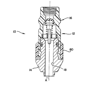
Turning now to the drawings, Figure 1 shows a
sectional view of a check valve 10 which incorporates a
presently preferred embodiment of this invention. The
check valve 10 includes a valve body assembly 12 which is
made up of a first valve body part 14 and a second valve
body part 16. A central passageway 18 extends
longitudinally through the valve body assembly 12 along
a longitudinal axis A.
As best shown in Figure 2, the first, or lower,
valve body part 14 defines a braze port 20 at one end and
a protruding neck 22 at the other end. An O-ring seal 24
is mounted in a groove formed in the outer surface of the
protruding neck 22. The protruding neck 22 also defines
an annular groove 26 defining a first abutment surface 28
oriented generally transversely to the axis A and facing

-- 3 --

- 4 _ 2~ 5
-


away from the O-ring seal 24. A larger diameter portion
is interposed between the braze port 20 and the
protruding neck 22, and the transition between the larger
diameter portion 30 and the neck 22 is defined by a
second abutment surface 32, which also extends generally
transverse to the axis A and faces toward the O-ring seal
24.
In this embodiment the first valve body part 14
is formed of a metallic material such as aluminum, brass,
or steel. The braze port 20 is shaped to fit into an
opening in a metallic tube (not shown) such that the
first valve body part 14 can be brazed in place in the
tube.
Figures 3-5 provide additional views of the
second, or upper, valve body part 16, which defines an
annular valve seat 40 extending around the central
passageway 18. A portion of the central passageway 18 is
enlarged in the second valve body part 16, and the second
valve body part 16 defines an annular recess 42 at this
enlarged portion. Additionally, the second valve body
part 16 defines a circular annular flange 44 which
extends generally parallel to the axis A. This flange 44
terminates in four hook elements 46, each of which
comprises a respective shaft 48 and hook 50. The shafts
48 extend generally parallel to the axis A, and adjacent
ones of the hook elements 46 are separated by recesses
52. The upper portion of the second valve body part 16
defines an annular circular ridge 54 shaped to engage a
conventional quick disconnect coupler (not shown).
The second valve body part 16 defines an outer
sidewall 56 and an inner sidewall 58. The inner sidewall
58 is shaped to receive the neck 22 in a telescoping
manner. In this embodiment the outer sidewall 56 is
generally frusto-conical in shape, with a larger diameter
adjacent the hooks 50 and a smaller diameter adjacent the

2~ S5

recess 42. By way of example, the angle of taper may be
approximately 2~.
A retainer 60 is secured in place in the recess
42, and this retainer 60 defines a central sleeve 62
which is held in position by radial supports 64. A valve
pin 66 is mounted for longitudinal movement along the
axis A in the central sleeve 62. This valve pin 66
defines an elastomeric sealing head 68 which is shaped to
seal against the valve seat 40. A spring 70 biases the
elastomeric sealing head 68 into engagement with the
valve seat 40.
A slide 80 is positioned around the second
valve part 16. The slide 80 defines an inner sidewall 82
which defines a plurality of male locking teeth 84
(Figure 6). The outer sidewall 56 of the second valve
body part 16 defines a plurality of female locking teeth
86. In this embodiment the inner sidewall 82 of the
slide 80 is cylindrical, and has a diameter somewhat
greater than the minimum diameter of the outer sidewall
56 but somewhat less than the maximum diameter of the
outer sidewall 56.
The slide 80 can be reciprocated on the second
valve body part 16 between a first position as shown in
Figure 3 and a second position as shown in Figures 1 and
6. In the first position (Figure 3) the slide 80 is
spaced from the hooks 50, and the slide 80 does not in
any way restrict radially outward movement of the hooks
50. In the second position (Figures 1 and 6) the slide
80 overlaps the hooks 50 and positively prevents them
from moving radially outwardly, out of engagement with
the groove 26.
In this preferred embodiment the second valve
body part 16, the retainer 60, and the slide 80 are all
formed of a polymeric material such as Nylon 6/6 or Nylon
12/12. The spring 70 is preferably formed of the
stainless steel, and the pin 66 is preferably formed of

r Za~jg~ff5 )


brass. Further detail~ regarding preferred material~ ~or
the spring 70 and the pin 66 may be found in U.S. Pat.
4,979,721.
Simply by way of illustration, and in order to
de~ine the pre~ently preferred ~mboAi~ent of this
invention, the protruding neck 22 may be provided with an
outer diameter of 0.416 inches and the inner sidewall 58
may be provided with a diameter of 0.431 1nches. The
outer sidewall 56 may be tapered from a minimum dimension
of 0.512 inches to a maximum dimension of 0.530 inches,
and the slide 80 may be provided with an inner sidewall
82 diameter o~ 0.524 inches.

OPERATIO~
In operation the fir-~t valve body part 14 is
fir~t in~talled on a tube (not shown) by brazing the
braze port 20 in place. Prior to assembly of the valve
body parts 14, 16, the val~e pin 66 is inserted in the
retainer 60, and the retainer 60 is positively secured in
place in the second valve body part 16, as for example by
spin welding, ultrasonic welding, a ~uitable adhesive or
a press fit. The ~ealing effectiveness of the as~embled
6econd ~alve body part 16 can be te~ted in order to
in~ure proper operation prlor to final assembly.
In order to as~emble the valve body parts 12,
14, the slide 80 i~ positioned in the first position as
shown in Figure 3 and the ~econd valve body part 16 is
snapped in place on the first valve body part 14. The
protruding neck 22 is received within the inner sidewall
58, and the O-ring ~eal 24 forms a seal against the inner
sidewall 58. During assembly the h~ok~ 50 initially move
radially outwardly. They then snap back into po6ition,
in engagement with the groove 26. The fir~t abutment
surface 28 cooperates wieh the hooks 50 to lock the valve
body parts 14, 16 together.
.


-- 6


,~,;~*."

~ - 7 - ~ S5
Once the valve body parts 14, 16 have been
snapped togetner, the retainer 60 is positively captured
in place, providing additional structural strength. At
this point, the slide 80 is moved from the first position
of Figure 3 to the second position of Figures 1 and 6.
As shown the male and female locking teeth 84, 86 are
asymmetrical such that they resist movement of the slide
80 out of the second position of Figure 6 with a much
greater force than they resist movement of the slide 80
into the second position. Preferably, a pliers-like tool
(not shown~ can be used to move the slide 80 into the
position of Figure 6.
As the slide 80 is moved to the second position
of Figure 6 it accomplishes a number of functions.
First, it positively captures the hooks 50 in the groove
26 to prevent disassembly of the first and second valve
body parts 14, 16. Second, the slide 80 cooperates with
the tapered outer sidewall 56 to compress the inner
sidewall 80 against the O-ring seal 24 to improve sealing
characteristics. The disclosed valve 10 has been found
to seal successfully at high pressures of greater than
600 psi.
If it is necessary to replace the second valve
body part 16, the slide 80 can be moved to the position
of Figure 3, and then the second valve body part 16 can
be twisted off of the first valve body part 14. The
slide 80 cannot be moved to the first position without
damaging either the slide 80 or the second valve body
part 16, and the second valve body part 16 is intended
for one use only. This prevents accidental or simple
manual disengagement of the valve body parts 14, 16.
Because the second valve body part 16 is formed of a
polymeric material while the first valve body part 16 is
formed of a metallic material, it is most unlikely that
the first valve body part 14 will be damaged and that
replacement will be required. Previous problems

- 8 - 2~9SS
associated with threaded connections between the valve
body parts are completely eliminated. This reduces the
prospect of damage to the first valve body part 14, and
it makes the use of polymeric materials for the second
valve body part 16 feasible.
Of course, it should be understood that a wide
range of changes and modifications can be made to the
preferred embodiment described above. For example,
dimensions, proportions, configurations and materials can
all be adapted as appropriate for the application of
interest. As is well known, charging valves on the high
and low side of an air conditioning system will differ in
diameter, and it is contemplated that this invention can
readily be adapted for use at either location.
It is therefore intended that the foregoing
detailed description be regarded as illustrative rather
than limiting, and that it be understood that it is the
following claims, including all equivalents, which are
intended to define the scope of this invention.

Representative Drawing
A single figure which represents the drawing illustrating the invention.
Administrative Status

For a clearer understanding of the status of the application/patent presented on this page, the site Disclaimer , as well as the definitions for Patent , Administrative Status , Maintenance Fee  and Payment History  should be consulted.

Administrative Status

Title Date
Forecasted Issue Date 1997-10-07
(22) Filed 1992-01-23
Examination Requested 1992-01-23
(41) Open to Public Inspection 1992-07-31
(45) Issued 1997-10-07
Deemed Expired 2009-01-23

Abandonment History

There is no abandonment history.

Payment History

Fee Type Anniversary Year Due Date Amount Paid Paid Date
Application Fee $0.00 1992-01-23
Registration of a document - section 124 $0.00 1992-09-02
Maintenance Fee - Application - New Act 2 1994-01-24 $100.00 1994-01-19
Maintenance Fee - Application - New Act 3 1995-01-23 $100.00 1995-01-11
Maintenance Fee - Application - New Act 4 1996-01-23 $100.00 1996-01-18
Maintenance Fee - Application - New Act 5 1997-01-23 $150.00 1997-01-22
Final Fee $300.00 1997-05-07
Maintenance Fee - Patent - New Act 6 1998-01-23 $350.00 1998-05-01
Maintenance Fee - Patent - New Act 7 1999-01-25 $350.00 1999-03-17
Maintenance Fee - Patent - New Act 8 2000-01-24 $150.00 2000-01-04
Maintenance Fee - Patent - New Act 9 2001-01-23 $350.00 2002-01-03
Maintenance Fee - Patent - New Act 10 2002-01-23 $200.00 2002-01-03
Maintenance Fee - Patent - New Act 11 2003-01-23 $200.00 2003-01-02
Maintenance Fee - Patent - New Act 12 2004-01-23 $250.00 2004-01-22
Maintenance Fee - Patent - New Act 13 2005-01-24 $250.00 2004-12-16
Maintenance Fee - Patent - New Act 14 2006-01-23 $250.00 2005-12-14
Maintenance Fee - Patent - New Act 15 2007-01-23 $450.00 2006-12-15
Owners on Record

Note: Records showing the ownership history in alphabetical order.

Current Owners on Record
BRIDGE PRODUCTS, INC.
Past Owners on Record
GILBERT, MAJOR H.
Past Owners that do not appear in the "Owners on Record" listing will appear in other documentation within the application.
Documents

To view selected files, please enter reCAPTCHA code :


To view images, click a link in the Document Description column. To download the documents, select one or more checkboxes in the first column and then click the "Download Selected in PDF format (Zip Archive)" or the "Download Selected as Single PDF" button.

List of published and non-published patent-specific documents on the CPD .

If you have any difficulty accessing content, you can call the Client Service Centre at 1-866-997-1936 or send them an e-mail at CIPO Client Service Centre.


Document
Description 
Date
(yyyy-mm-dd) 
Number of pages   Size of Image (KB) 
Cover Page 1997-10-01 1 52
Abstract 1993-11-27 1 23
Cover Page 1993-11-27 1 15
Claims 1993-11-27 7 248
Drawings 1993-11-27 2 56
Description 1993-11-27 8 348
Description 1996-12-10 8 323
Claims 1996-12-10 6 214
Representative Drawing 1997-10-01 1 10
Fees 1997-01-22 1 37
Fees 1995-01-11 1 30
Fees 1996-01-18 1 33
Fees 1994-01-19 1 28
Prosecution Correspondence 1992-01-23 15 701
Office Letter 1992-09-14 1 47
Correspondence Related to Formalities 1997-05-07 1 35
Prosecution Correspondence 1996-10-01 4 169
Prosecution Correspondence 1996-10-01 8 475
Examiner Requisition 1996-04-12 2 69