Note: Descriptions are shown in the official language in which they were submitted.
2060122
Description
Main Rotor Assembly Support Truss
Technical Field
The subject matter of the present invention
relates generally to helicopters, and more
particularly, to a support truss that is configured
to structurally support the main rotor assembly of a
helicopter in integrated combination with the
helicopter airframe and to transmit dynamic and
static loads of the main rotor assembly into the
helicopter airframe at two different load transfer
levels.
Background of the Invention
Large magnitude dynamic and static longitudinal,
lateral, vertical, and torsional loads are developed
by the main rotor assembly of a helicopter.
Helicopter design methodology utilizes a support
structure to integrate elements of the main rotor
assembly such as the static rotor mast and the engine
transmission in combination with the airframe of the
helicopter. Such support structures are configured
to transmit the dynamic and static longitudinal,
lateral, vertical, and torsional loads developed by
the main rotor assembly to the airframe of the
helicopter at a single load transfer level (the
transmission deck).
Representative embodiments of prior art main
rotor assembly (MRA) support structures are
illustrated in Figures lA-1C. Figures lA, 1B depict
standpipe support structures SP having a plurality of
attachment feet AF. Figure lA represents the
S-4495 - 1 -
2060122
configuration of a generalized embodiment of the
standpipe support structure SP. The static rotor
mast and the transmission of the main rotor assembly
are integrated with the attachment collar AC of the
standpipe support structure SP. Figure 1B
illustrates the particularized embodiment of the
standpipe support structure SP currently utilized on
Sikorsky Blackhawk and S-76 helicopters. In this
type of standpipe support structure SP, the
transmission housing TH of the main rotor assembly
comprises the body of the support structure,
including the attachment feet AF. The static rotor
mast is integrated with the attachment collar THAC of
the transmission housing TH.
Each of the above-described embodiments of MRA
standpipe support structures SP is secured to the
transmission deck of the helicopter by means of bolts
passing through the attachment feet AF. The dynamic
and static loads of the main rotor assembly are
transmitted to a single load transfer level of the
airframe (the transmission deck) via the attachment
feet AF. Prior art standpipe support structures
offer several advantages, including relative ease and
low cost of fabrication as an integral unit, and ease
of attachment to the transmission deck. Due to the
relatively uncluttered configuration of prior art
standpipe support structures SP, hydraulic lines,
subsystem wiring, and other interfacing elements
typically routed over the transmission deck may be
readily run over/adjacent the exterior surface of
prior art standpipe support structures SP.
On the other hand, prior art standpipe support
structures SP are disadvantageous in several
respects. Due to the manner of integration of the
S-4495 - 2 -
2060122
transmission with the standpipe support structure,
the transmission housing acts as a structural member
through which the dynamic and static loads of the
main rotor assembly are intermediately transmitted.
5 Moreover, the weight of the standpipe support
structure is relatively large because of the high
structural strength required of the support
structure.
The high strength requirement is due primarily
10 to the low profile configuration of the support
structure and the effective load points of the main
rotor assembly dynamic and static loads to which the
standpipe support structure SP is subjected. The
effective load points of the dynamic and static loads
15 of the main rotor assembly have relatively large
moment arms with respect to the low profile support
structure, see Figure 1D, which intensifies the
loading effects experienced at the attachment feet AF
(concomitantly, these loading effects also
20 necessitate an increase in airframe structural
strength in the load transfer zones (hardpoints) of
the transmission deck). In addition, each of the
attachment feet AF must be sized to accommodate the
ultimate flight load conditions (fail-safe
25 redundancy) and crashworthiness high mass retention
(controlled displacement of the main rotor assembly
in crashes).
Routine maintenance is more time consuming and
labor intensive for prior art standpipe-type support
30 structures SP. Any type of transmission maintenance
(including removal of the transmission) requires
removal of the rotor head, mast, and associated
components prior to initiation of maintenance. The
removed components must be reassembled and the
S-4495 - 3 -
2060122
operation thereof checked after completion of any
routine transmission maintenance/overhaul.
An MRA strut support structure ST is illustrated
in Figure 1C. The strut-type support structure ST is
5 currently utilized on the McDonnell-Douglas Apache
attack helicopter. The strut support structure ST is
a high profile configuration comprising an
integration member IM, and a plurality of struts S
such as cylindrical rods or machined legs extending
10 from the integration member IM and terminating in
attachment feet AF.
The static rotor mast of the main rotor assembly
is attached to the integration member IM in a manner
similar to the standpipe support structure ST. The
15 transmission, however, is attached in suspended
combination to the underside of the integration
member IM, and consequently, is not part of the
transmission path for the dynamic and static loads of
the main rotor assembly. The attachment feet AF of
20 the MRA strut support structure ST are utilized to
secure the support structure to the airframe of the
helicopter and to transfer dynamic and static loads
of the main rotor assembly to respective hardpoints
of a single level load transfer plane (transmission
2 5 deck ) .
Due to the high profile configuration of the MRA
strut support structure ST, however, the dynamic and
static loads of the main rotor assembly are
transmitted to single load transfer plane through the
30 integration member IM. In consequence, the loading
effects at the attachment feet AF (and in the
respective hardpoints of the transmission deck) are
not as severe as those experienced in the
standpipe-type support structure ST.
S-4495 - 4 -
2060122
Each of the struts S must be equally sized to
react the maximum longitudinal, lateral, vertical,
and torsional dynamic loads developed by the main
rotor assembly, which increases the overall weight of
the MRA strut support structure ST. Moreover, in
light of the high profile configuration of the strut
support structure ST, each strut S must be oversized
to accommodate not only the dynamic loading developed
by the main rotor assembly, but also the bending
stresses that may be experienced in the event of the
loss of any one strut S (fail-safe redundancy).
The routing of hydraulic lines, electrical
subsystem wiring, and other interface components
along the transmission deck is complicated by the
network of struts S. Transmission maintenance and/or
removal is simplified to the extent that access to
the transmission does not require removal of the main
rotor head, static rotor mast, and associated
components. However, extraneous time and labor is
required for transmission maintenance/removal
inasmuch as one set of struts S must be removed to
access the transmission. The configuration of MRA
strut support structure ST is more complex than the
MRA standpipe support structure SP, thereby requiring
more time and labor to install and/or remove the
strut-type support structure ST.
A need exists for a MRA support structure that
has a relatively simple configuration with a
relatively high profile. The support structure
should be lightweight, inexpensive, relatively simple
to fabricate, and readily secured to the helicopter
airframe. Such a support structure should have a
configuration that facilitates integration of the
main rotor assembly therewith in such a manner that
S-4495 - 5 -
2060122
the engine transmission is non-structural (does not
act as a transmission path for dynamic and static
loads of the main rotor assembly). The support
structure should provide fail-safe redundancy
S (ballistic tolerance) and crashworthiness high mass
retention without a corresponding increase in
structure weight.
The support structure should facilitate access
to the transmission for maintenance/removal, i.e.,
not require removal of components of the main rotor
assembly. The support structure should also
facilitate routing of hydraulic lines, electrical
subsystem wiring, and other interface components
along the transmission deck.
Summary of the Invention
A main rotor assembly (MRA) support truss
according to the present invention has a relatively
simple configuration that is lightweight, relatively
simple and inexpensive to fabricate, facilitates
access to the transmission for maintenance/overhaul,
and facilitates routing of hydraulic lines,
electrical subsystem wiring, and other interface
components along the transmission deck. The
configuration of the support truss is readily secured
to the helicopter airframe, and facilitates
integration of the main rotor assembly therewith.
The MRA support truss of the present invention is
configured for utilization with helicopters having a
gusset structure that is located at the forward end
of the transmission deck and which extends vertically
upwardly with respect thereto.
The MRA support truss is structurally configured
to support elements of the main rotor assembly of a
S-4495 - 6 -
2060122
helicopter such as the static rotor mast and the
transmission in integrated combination with the
airframe of the helicopter. The configuration of the
MRA support truss is operative to transmit dynamic
and static longitudinal, lateral, vertical, and
torsional loads of the main rotor assembly into the
airframe of the helicopter. The configuration
provides transmission paths for dynamic and static
loading into airframe hardpoints at two different
load transfer levels.
The MRA support truss is an integral forged
structure that is machined to final configuration,
and is preferably formed from a high strength,
electrically conductive metallic material such as an
aluminum alloy. An MRA support truss formed from an
electrically conductive material may be utilized as
the primary electrical ground bus for electrical
subsystems of the helicopter, and in addition, may
function as a highly conductive path for lightning
strikes.
The MRA support truss comprises a cylindrical
body member, a pair of aftwardly extending support
struts terminating in attachment feet, a pair of
forward facing primary support ribs terminating in
attachment feet, and a forward facing secondary
support rib, positioned intermediate the primary
support ribs, terminating in an attachment foot. A
cross stringer extends between and integrally
interconnects the primary and secondary support ribs.
The attachment feet are configured to secure the MRA
support truss to the helicopter airframe at two
distinct, spaced-apart load transfer levels.
The primary support ribs function as a shear
attachment for the MRA support truss to the airframe
S-4495 - 7 -
2060122
structural members of the gusset structure. The
primary support ribs are operative to transmit
dynamic and static longitudinal, lateral, vertical,
and all torsional loads developed by the main rotor
5 assembly to the helicopter airframe at the primary
load transfer level.
Since the primary support ribs comprise the
primary load transfer structure of the MRA support
truss, they are sized accordingly - higher weight to
10 provide increased structural strength. The primary
support ribs, however, have a low profile
configuration with respect to the centers of gravity
of the elements of the main rotor assembly
contributing to dynamic and static loading such that
15 upsizing the primary support ribs does not provide a
significant increase in overall weight to the MRA
support truss.
The aft support struts provide a tension
attachment for the l~tA support structure to the keel
20 beams of the transmission deck that defines the
secondary load transfer level of the helicopter
airframe. The aft support struts are operative to
transmit only axial loads to the second load transfer
level. Because of the limited load transmission
25 function of the aft support struts, they may have a
downsized configuration, i.e., less weight.
Due to the downsized configuration and limited
load transmission function of the aft support struts,
they also provide a unique crashworthiness high mass
30 retention function for the MRA support truss.
Fail-safe redundancy is provided by the secondary
support rib.
The MRA support truss further includes an upper
attachment flange for securing the static rotor mast
S-4495 - 8 -
~0~0122
in combination with the MRA support truss and a
lower attachment flange for securing the
transmission in suspended combination with the MRA
support truss. The cylindrical body member of the
MRA support truss may also be configured to include
a plurality of integral servo lugs that function as
lower attachment points for rotor servo actuators of
the main rotor assembly.
In accordance with a particular embodiment
of the invention there is provided, for a helicopter
having a main rotor assembly that develops dynamic
and static longitudinal, lateral, vertical, and
torsional loads, a transmission, and an airframe
that includes a gusset structure and a transmission
deck, a main rotor assembly support truss,
comprising:
body member means configured for
supporting the main rotor assembly in integrated
combination with the helicopter airframe, said body
member means including means for securing the
transmission in suspended combination with said main
rotor assembly support truss;
first and second parallel, spaced apart
forward facing support ribs integral with said body
member means and including means for securing said
first and second forward facing support ribs to the
gusset structure, said first and second forward
facing support ribs provide a shear attachment for
said main rotor assembly support truss and are
configured and sized for transmitting the dynamic
and static longitudinal, lateral, vertical, and all
torsional loads of the main rotor assembly to the
gusset structure that functions as a primary load
transfer plane of the helicopter airframe; and
first and second spaced apart aftwardly
extending support struts integral with said body
- 9 -
~0~0~2~
member means and including means for securing said
first and second aftwardly extending support struts
to the transmission deck, said first and second
aftwardly extending support struts provide a tension
attachment for said main rotor assembly support
truss and are configured and sized for transmitting
axial loads of the main rotor assembly to the
transmission deck that functions as a secondary load
transfer plane of the helicopter airframe.
A more complete understanding of the
present invention and the attendant advantages and
features thereof will be more readily comprehended
by reference to the following detailed description
when considered in conjunction with the accompanying
drawings wherein.
Figures lA, 1B illustrate prior art
standpipe support structures for the main rotor
assembly of a helicopter.
Figure 1C illustrates a prior art strut
support structure for the main rotor assembly of a
helicopter.
Figure 1D is an exemplary representation
of the dynamic loading experienced by the standpipe
support structure of Figure lA.
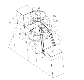
Figure 2 is a first perspective view of
one embodiment of a support truss for a main rotor
assembly according to the present invention.
Figure 3 is a second perspective view of
the main rotor assembly support truss of Figure 2.
Figure 4 is an exemplary representation of
the dynamic loading experienced by the main rotor
assembly support truss according to the present
invention.
- 9a -
2060122
Figure 5 is a perspective view of another
embodiment of a main rotor assembly support truss
according to the present invention.
Detailed Description of Preferred Embodiments
5 Referring now to the drawings wherein like
reference numerals identify corresponding or similar
elements throughout the several views, Figures 2, 3
illustrate one exemplary embodiment of a main rotor
assembly (MRA) support truss 10 according to the
10 present invention. The MRA support truss 10 is
configured to structurally support elements of a
helicopter main rotor assembly such as the static
rotor mast SRM and the transmission T in integrated
combination with the airframe of a helicopter (not
15 shown). Also illustrated in Figure 2 are portions of
the helicopter engines E which, although not directly
attached to the MRA support truss 10, transmit
dynamic loads to the MRA support truss 10 via the
transmission T (see also Figure 4). In addition, the
20 MRA support truss 10 may be configured to provide
servo lugs as lower attachment points for the rotor
servo actuators of the main rotor assembly.
The configuration of the MRA support truss 10 is
operative to transmit dynamic and static
25 longitudinal, lateral, vertical, and torsional loads
developed by the main rotor assembly into the
airframe of the helicopter. The configuration of the
MRA support truss 10 provides two transmission paths
for such dynamic and static loads into airframe
30 hardpoints (attachment points) at two distinct,
spaced-apart load transfer levels or planes of the
helicopter airframe.
S-4495 - 10 -
2060122
The prior art MRA support structures discussed
hereinabove are configured to transmit the dynamic
and static loads of the main rotor assembly into the
helicopter airframe at a single load transfer level
or plane. This load transfer level is the
transmission deck of the helicopter that lies
superjacent the fuselage center boxbeam. In
contrast, the MRA support truss 10 of the present
invention transmits dynamic and static main rotor
assembly loads at a primary load transfer level and a
secondary load transfer level. The secondary load
transfer level is the transmission deck TD of the
helicopter. The primary load transfer level is a
gusset structure GS.
The MRA support structure 10 of the present
invention is configured to be utilized in helicopters
having a gusset structure GS that is located at the
forward end of the transmission deck TD and which
extends vertically upwardly with respect thereto. In
such helicopters, the gusset structure GS is a
preexisting structural feature that performs several
structural functions. The gusset structure GS
supports the seat of the copilot (which is situated
directly behind and elevated in plane with respect to
the pilot's seat). The gusset structure GS further
acts as the upper support structure for the
helicopter canopy. The main shock struts of the
landing gear may extend into and be supported by the
gusset structure GS. The gusset structure GS may
also serve as a mounting point for a wire cutter, a
device for severing power or phone transmission lines
or the like before they contact the main rotor
assembly. With reference to Figures 2, 3, the gusset
structure GS is identified by the reference
S-4495 - 11 -
2060122
letters GS while the transmission deck is identified
by the reference letters TD.
The MRA support truss 10 of the present
invention is an integrally forged structure that is
5 machined to final form. The relatively simple
configuration of the MRA support truss 10 simplifies
the process of fabricating the support truss 10 as an
integral structure, and also facilitates mounting of
the support truss 10 in combination with the
10 helicopter airframe. The MRA support truss 10 is
preferably formed from a high strength, electrically
conductive metallic material such as an aluminum
alloy, e.g., 7075 aluminum.
An MRA support truss 10 fabricated from a high
15 strength conductive metallic material provides
additional functions in addition to those described
hereinabove. The electrically conductive MRA support
truss 10 may be utilized as the primary electrical
ground bus for electrical subsystems of the
20 helicopter, thereby providing overall system weight
and cost savings. The electrically conductive MRA
support truss 10 may also function as a highly
conductive path for lightning strikes to the airframe
and/or skin of the helicopter.
25 It is to be understood that the MRA support
truss 10 may also be formed from less dense, high
strength metallic materials that are poor conductors
to lower overall system weight. The use of a lighter
weight, non-conductive MRA support truss 10, however,
30 should be examined from a system perspective, i.e.,
the benefits of the lighter weight support truss
should be balanced against such factors as increased
cost, installation time, weight, and the ensuing
complexity of providing separate electrical ground
S-4495 - 12 -
2060122
buses and/or a separate grounding path to the
helicopter airframe for lightning strikes.
The MRA support truss 10 according to the
present invention comprises a generally cylindrical
5 body member 12, a pair of aftwardly extending support
struts 14 terminating in attachment feet 16, a pair
of forward facing primary support ribs 18 terminating
in attachment feet 20, and a forward facing secondary
support rib 22, positioned intermediate the primary
10 support ribs 18, terminating in an attachment foot
24. A cross stringer 26 extends between and is
integrally interconnected with the primary support
ribs 18 and the secondary support rib 22 adjacent the
attachment feet 20, 24 thereof. The cross
15 stringer 26 functions to maintain the structural
integrity of the MRA support truss 10 during
torsional loading.
The attachment feet 16 of the aft support struts 14
are configured (C-channel close-out flange) to secure
20 the aft support struts 14 to keel beams of the
transmission deck TD (via securing bolts). Bathtub
fittings BF, which are part of the transmission
deck TD, are utilized to integrate the aft support
struts 14 in combination with the keel beams. The
25 attachment feet 20, 24 are configured to secure the
primary support ribs 18 and the secondary support rib
22, respectively, to airframe structural members of
the gusset structure GS (via securing bolts).
With reference to Figure 4, the primary support
30 ribs 18 provide a shear attachment for the MRA
support truss 10 to the airframe structural members
of the gusset structure GS. The primary support ribs
18 are operative to transmit dynamic and static
longitudinal, lateral, vertical, and all torsional
S-4495 - 13 -
2060122
loads developed by the main rotor assembly to the
gusset structure GS, which is defined as the primary
load transfer level TL1. Since the primary support
ribs 18 comprise the primary load transfer structure
of the MRA support truss 10, they are sized
accordingly - higher weight to provide increased
structural strength. The primary support ribs 18,
however, have a low profile configuration with
respect to the centers of gravity of the elements of
the main rotor assembly contributing to dynamic and
static loading (see discussion hereinabove) such that
upsizing the primary support ribs 18 does not provide
a significant increase in overall weight to the MRA
support truss l0.
The aft support struts 14 provide a tension
attachment for the MRA support truss 10 to the keel
beams of the transmission deck TD that define a
secondary load transfer level TL2. The aft support
struts 14 are operative to transmit only axial loads
to the second transfer level TL2. Because of the
limited load transmission function of the aft support
struts 14, they may have a downsized configuration,
i.e., less weight.
As a result of the downsized configuration and
limited load transmission function of the aft support
struts 14, the aft support struts 14 also provide a
unique crashworthiness high mass retention function
for the MRA support truss 10 according to the present
invention. In the event of a vertical crash
exceeding worst case design loads (about 20g's for
one embodiment), the aft support struts 14 will fail
first, buckling in compression. This causes the MRA
support truss 10 to rotate aftwardly about the
attachment feet 20, 24 of the primary and secondary
S-4495 - 14 -
2060122
support ribs 18, 22. Aftward rotation of the MRA
support truss 10 causes a concomitant aftward
rotation of the main rotor assembly including the
main rotor blades, which greatly reduces the
probability of a rotor blade strike on the canopy.
Fail-safe redundancy is provided by the
secondary support rib 22 which is sized for crash
loads in the event of a loss of either of the primary
support ribs 18. In the event of such loss, for
example by structural failure or ballistic
destruction, the load transmission function of the
lost primary support rib 18 will be assumed by the
secondary support rib 22. In addition, due to the
limited load transmission function of the aft support
struts 14, the primary support ribs 18 (or one of the
primary support ribs 18 and the secondary support
rib 22) possess sufficient structural strength to
provide fail-safe redundancy in the event of the loss
of one of the aft support struts 14.
The MRA support truss 10 illustrated in Figure 2
further includes an upper attachment flange 28 and a
lower attachment flange 30. The upper attachment
flange 28 is utilized to secure the static rotor
mast SRM of the main rotor assembly in combination
with the MRA support truss 10. The upper attachment
flange 28 illustrated in Figures 2, 3 is a reverse
flange having a configuration that facilitates
integration of the static rotor mast with the MRA
support truss 10. The reverse attachment flange 28
also facilitates in-place lowering of the static
rotor mast for transportability. Another embodiment
of the MRA support truss 10 is depicted in Figure 5
and illustrates an outwardly extending upper
attachment flange 28. With an outwardly extending
S-4495 - 15 -
2060122
flange 28, the static rotor mast must be removed for
transportability.
The lower attachment 30 secures the
transmission T in suspended combination with the MRA
support truss 10. The suspended transmission is
readily accessible (no elements of the MRA support
truss 10 need to be removed for, or obstruct, access
to the transmission) for maintenance/removal, which
significantly reduces the time and labor required for
10 routine transmission maintenance and/or removal.
Dynamic and static loads of the main rotor
assembly are transmitted via the static rotor mast to
the cylindrical body member 12 of the MRA support
truss 10 via the upper flange attachment 28. The
15 main rotor shaft passes through the concentric
channel defined by the cylindrical body member 12 for
integration with the suspended transmission.
The MRA support truss l0 may also include a
plurality, typically three, of servo lugs 32 as
20 illustrated in Figures 2, 3 and 5. The servo lugs 32
are integrally formed as part of the cylindrical body
member 12 and spaced thereabout. The servo lugs 32
function as lower attachment points for rotor servo
actuators RSA (see Figure 2) of the main rotor
25 assembly. Fabrication of the MRA support truss 10 to
include such servo lugs 32 provides an additional
advantage over prior art MRA support structures which
do not have such a feature, which thereby
necessitates the use of separately fabricated and
30 installed anchors for the lower attachment points of
the rotor servo actuators.
A variety of modifications and variations of the
present invention are possible in light of the above
teachings. It is therefore to be understood that
S-4495 - 16 -
2060122
within the scope of the appended claims, the present
invention may be practiced otherwise than as
specifically described hereinabove.
S-4495 - 17 -