Note: Descriptions are shown in the official language in which they were submitted.
-
1- 206~77
FLUID W~TE BURNER SYSTEM
T~CHNIC~T FI~LD
The present invention pertains to a process
and apparatus for controlling the temperature and
flame front in waste incinerators. The apparatus
includes, inter alia, a novel and improved burner
system for incinerating fluid waste streams.
BACKGROUND OF TH~ INVENTION
Many industrial processes produce fluid
waste streams which may contain water and bio- and
non-biodegradable components. The non-biodegradable
components could be environmentally hazardous
materials, such as acids, chlorinated solvents a.o..
Commonly, these fluid waste streams are incinerated
in a fi~ed or rotary furnace. The resulting flue gas
from burning these streams is usually treated to
remove pollutants, such as CO, SO2, and/or C12.
Carbon mono~ide, for example, can be oxidized to form
C~2 while C12 and SO2 can be chemically removed,
i.e., by reacting them with alkali or alkaline
materials. Filtering means may also be used to
remove dust if it is present in the flue gas.
It has been known to employ air/fuel burners
in a furnace to incinerate fluid waste streams. The
air/fuel burners, however, are generally inefficient
in burning fluid waste. Much time may be necessary
to evaporate water, if present, and then burn the
bio- and non-biodegradable components, thereby
limiting a rate at which the fluid waste streams are
introduced into a furnace for incineration. This
problem is compounded by a high volume of a flue gas
D-16508
- - 2 - 2060477
which usually results from employing air/fuel burners
in incinerating the fluid waste. As the volume of a
flue gas increases, the throughput of a furnace is
decreased. The term "throughput" is defined as ~a
rate at which a liquid waste stream is fed to a
furnace for incinerationn.
To enhance the throughput of a furnace, the
use of o~ygen enriched air or lancing pure o~ygen in
or under the air flame, has been employed. These
oxygen techniques, however, are believed to have a
number of disadvantages. One of the common
disadvantages of pure oxygen lancing includes a
partial mixing of the oxygen with the air flame
leading to less than the e~pected increased
throughput and to an eventual uncontrollable flame
front which could cause possible overheating of
downstream filter equipment. Another disadvantage of
higher oxygen enrichment levels of the combustion
air, is the possible overheating of the furnace
refractory in the vicinity of the air flame area.
Therefore, there is a need to find a means
by which a throughput rate can be increased without
creating unstable and uncontrolled flames and
temperature conditions, which could be deleterious to
a fluid waste furnace or a liquid waste incinerator
and its subsequent communicating off-gas cleaning
system.
SUMMARY OE THE INVENTIO~
The present invention represents an
improvement in liquid and/or gaseous waste
incineration technology by increasing the throughput
D-16508
' 3 2060477
capacity of incinerators without causing any harmful
effects associated therewith to the incinerator and
its subseguent communicating off-gas cleaning system.
This increased throughput capacity is
obtained by the "synergetic~ effect of several
factors influencing the combustion itself and the
improved control of the furnace operation, together
with shifting from commercial fossil fuel or natural
gas to a high heating value liquid and/or gaseous
waste as a heat source for the incinerating process.
According to one embodiment of the present
invention, this improvement is accomplished in a
process and/or apparatus for controlling the
temperature and flame front in a waste incinerator
comprising: dispersing fluid waste into the flame to
incinerate the fluid waste in and around said flame,
wherein flame energy is regulated to confine the
flame front within said incinerator and to maintain a
preselected temperature within the incinerator. The
flame is engendered by combusting fuel, such as
fossil fuel, natural gas or a high heating value
liquid or gaseous waste in the presence of ogygen.
The term "flame energy" is therefore, defined by a
ratio of the high heating value waste and/or fossil
fuel rate to the low heating value fluid waste rate.
Such a ratio can be adjusted to confine the flame
front within said incinerator and to maintain the
preselected temperature in said incinerator since the
low heating value fluid waste is being dispersed into
the flame.
The fluid waste is introduced into the flame
produced by at least one oxygen/fuel burner via at
D-16508
_ 4 _ 2060477
least one nozzle means which is placed within an
annulus formed by a housing means surrounding said at
least one oxygen/fuel burner. At least one nozzle
means may be bent inwardly such that said fluid waste
is dispersed into the flame of said at least one
oxygen/fuel burner. The fluid waste may comprise a
mixture of liquid and gaseous waste, each of which
~eing separately dispersed into the flame of said at
least one oxygen/fuel burner through a separate
nozzle of said at least one nozzle means. Through
the annulus, oxidant is also introduced to stabilize
the flame of said at least one o~ygen/fuel burner and
to enhance the burning of the bio- and
non-biodegradable components. Means for imparting a
whirling effect to said oxidant such as ribs and
baffles can be provided within the annulus.
According to another embodiment of the
present invention, this improvement can be achieved
in a fluid waste incineration system comprising:
a. a burner system having means for
engendering a flame and means for dispersing fluid
waste into said flame in a furnace;
b. at least one conduit means for
transporting a fluid waste from a fluid waste source
to said meahs for dispersing said fluid waste;
c. a flue gas treating means in
communication with the furnace to remove pollutants
in the flue gas resulting from burning the fluid
waste in the furnace; and
d. means for transporting the flue gas
from the furnace to heat the fluid waste prior to
dispersing the fluid waste into the flame.
D-16508
2060477
The means for engendering the flame
comprises at least one o~ygen/fuel burner. This
oxygen/fùel burner may be in communication with a
high heating value waste source which could provide a
high heating value waste, as a substitute for fossil
fuel, to engender a flame. The means for dispersing
the fluid waste comprises at least one nozzle means
placed within an annulus formed by a housing means
surrounding the oxygen/fuel burner. The means for
transporting the flue gas from the furnace to heat
the fluid waste include an evaporation system which
is in communication with the furnace via conduit
means. Means for regulating the liquid waste
atomization rate, the oxidant flow rate and the fuel
introduction rate are also provided to control the
flame of the o~ygen/fuel burner and the temperature
of the furnace. By using the flue gas to heat a low
heating value fluid waste, particularly a low heating
value liquid containing waste, which may be partially
concentrated as a result of heat, prior to
combustion, the reduction of the flue gas or off
gases in the furnace by an amount equal to the
quantity of water that had been evaporated can be
achieved. Combustion is also enhanced.
As used herein the term "fuel" means a high
heating value waste, fossil fuel and/or natural gas. -
As used herein the term n a high heatingvalue waste" means a waste having a heating value
equal to or greater than 3500 Kcal/kg.
As used herein the term"a low heating value
waste" means a waste having a heating value of less
than about 3500 Kcal/kg.
D-16508
- 2060477
As used herein the term ~fluid waste" means
liquid waste, gaseous waste or mixtures thereof.
As used herein the term "o~ygen/fuel burner~
means an oxygen burner which engenders a flame by
combusting fuel in the presence of oxidant having at
least 28% o~ygen concentration.
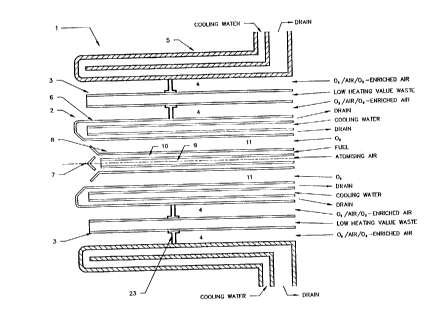
E~IEF DESCRIPTION OF T~ DRAWINGS
Figure 1 is a side cross-sectional view of
the improved burner system illustrating one
embodiment of the present invention.
~ igure Z is a side cross-sectional view of
the improved burner system having bent nozzles
illustrating one embodiment of the present invention.
Figure 3 is an end view of the improved
burner system of Figure 1.
Figures 4 and 5 are diagrammatic views of an
incineration system according to one embodiment of
the present invention.
DETAIT~n DESCRIPTION OF THE INV~TION
Referring to Figures 1-3, a burner system
(1) is illustrated in side and end views. The burner
system (1) has a centrally located oxygen/fuel burner
(2), which is an assembly consisting of the elements
numbered 6, 7, 8, 9, 10, 11, as shown in Figure 1 and
Figure 2, and a plurality of nozzles (3~ placed
substantially parallel to the centrally located
oxygen/fuel burner (2) within a water cooled annulus
(~) which is formed by a housing means having a water
jacket (5) surrounding the centrally located
oxygen/fuel burner (2). The oxygen/fuel burner (2)
~-16508
2060~77
includes a water cooled cylindrical pipe (6) which
protects a concentrically placed inner pipe (8)
terminating at a nozzle tip (7) from which fuel or
waste is emitted. The inner pipe (8) contains two
coaxially placed tubes wherein fuel flows to the
nozzle tip (7) through the outer tube or annulus (10)
and, air or any other atomizing agent is provided
through the central tube (g) to atomize the fuel at
the nozzle tip (7).
The preferred oxygen/fuel burner employed is
the aspirator ~urner described and claimed in U.S.
Patent No. 4,378,205 - Anderson or U.S. Patent No.
4,541,796 - Anderson, which is releasably mounted in
the burner system (1). The location of this
o~ygen/fuel burner ~2) is such that it is in the
center of the burner system (1) with its tip (7)
terminating at about 0 to about 0.3m retracted behind
the tips of the plurality of nozzles (3). The
oxidant employed in the oxygen/fuel burner and
flowing through the annulus (11) is preferably
technically pure oxygen having an o~ygen
concentration greater than 99.5 percent. The oxidant
having an oxygen concentration greater than 50
percent, however, can be employed. The o~idant
flowing through the annulus (4) may be technically
pure o~ygen having an oxygen concentration greater
than 99 5 percent or it may be air or oxygen-enriched
air having an o~ygen concentration of at least 21
percent or preferably greater than 30 percent. The
preferred fuel employed is the rich fossil fuel such
as oil, natural gas, or high heating value fluid
waste having a heating value of above 3500 kcal/kg.
D-16508
- 8 - ~ 4 7 ~
The plurality of nozzles (3) may also be
releasably mounted within the annulus (4) of the
burner system (1). Each nozzle (3) can be bent
inwardly toward the oxygen/fuel burner (2), a
preferred bent angle being 0~ to 40~, measured from
the central axis of each nozzle. The passageway of
each nozzle (3) is such that small solid particles of
up to 5 mm diameter or larger can pass through the
nozzle (3). Through these nozzles, a low heating
value fluid waste is dispersed into the flame of at
least one oxygen/fuel burner. Different low heating
value waste, such as gaseous or liquid waste, may be
separately introduced into the flame through separate
nozzles of said plurality of nozzles (3).
The waste streams entering the burner
system (1) and passing through the nozzle tip (7) and
the nozzles (3) preferably originate from different
sources and may therefore have different qualities
with respect to composition, heating value, viscosity
etc. These waste streams, however, may be derived
from the same source. One of the streams could be
treated to provide a high heating value.
In Figures 4 and 5, a fluid waste stream,
preferably a liquid containing waste stream, is
introduced from a waste source (10) into a furnace
(30) via conduits (12) and the plurality of nozzles
(3) of the burner system (1). The flow rate of the
fluid waste can be adjusted and/or controlled by a
regulating means (13).
For instance, the plurality of nozzles (3)
can be pressurized to atomize the liquid containing
waste into the furnace (30) at about 0 to about
D-16508
9 ~ 4 ~ 7
10,000 liters/hour or more. Each liquid waste stream
going through the nozzles (3) could contain from
about O to about 95% by volume water or more, the
remaining content of the liquid waste stream
comprising bio- and non-biodegradable components
which may be hazardous to the environment.
Fuel, such as high heating value waste, oil
or natural gas, and oxidant are also shown to be
supplied to the burner system (1) from a fuel source
(14) and an oxidant source (15) via conduits (16) and
(17), respectively, to operate the oxygen/fuel burner
(2). The fuel is supplied to the inner pipe (8) of
the oxygen/fuel burner (2) and the oxidant is
supplied to the pipe (6) through the annulus (11) of
the oxygen/fuel burner (2). The rates at which said
fuel and oxidant are supplied to the oxygen/fuel
burner are controlled by regulating means (18) and
(19), respectively. The amount of said fuel and
oxidant used is generally dependent on the amount and
the content of said liquid waste fed to the furnace
(30). Said oxidant, however, is preferably fed at
about 0 to 1000 Nm3/h or more while the fuel, such as
natural gas or oil or a high heating value waste, is
introduced at about 100 to 2000 Nm3/h (natural gas)
or at about 80 to 1600 liters/hour (oil or waste) or
more.
Furthermore, additional oxidant, such as
air, oxygen enriched air or pure oxygen, can be
introduced into the furnace (30) from an additional
oxidant source (20) or from the existing oxidant
source (15) via a conduit (21) and the annulus (4) of
the burner system (1) as shown in Figures 4 and 5.
D-16508
. ~
-- 10 --
4 ~ ~
The size of the annulus (4) is such that the oxidant
can be introduced to the furnace (30) at about 10,000
to 70,000 Nm3/h or more. The flow rate of the latter
oxidant provided through the annulus (4) is regulated
by a regulating means (22). Ribs or baffles (23-) may
be provided within the annulus (4) to impart a
whirling effect to oxidant passing through the
annulus (4).
During the incineration, the flame energy
is regulated or adjusted in order to prevent the
flame front from escaping the furnace (30) and to
control the temperature of the furnace (30), meaning
e.g. that one part of fuel, such as high heating
liquid waste or fossil fuel, is used together with 9
parts of low heating value aqueous waste. This ratio
is generally adjusted to 1/9 to about 1/4 based on
weight. The ratio, however, is largely dependent on
the heating value of a fluid waste stream and its
introduction rate. When, for example, a temperature
is decreased as a consequence of increased low
heating aqueous liquid waste introduction rate and
its associated water evaporation rate, a proportional
increase in the high heating value waste or fossil
fuel introduction rate is needed to compensate for
the temperature decrease resulting from a high volume
of water. The increased amount of fuel, such as high
heating value liquid or gaseous waste or fossil fuel,
contributes to an increase in the oxygen flame energy
which is necessary to incinerate a given amount of a
specific low heating value aqueous liquid waste.
Preferably, the low heating value fluid
waste is introduced at about 4000 to 9000 kg/h while
D-16508
r7 t~
the oxygen flame energy employed is about 3500 to
about 10.000 kcal/kg employing about 1000 kg/hr
fossil oil or about 1200 Nm3/hr natural gas or about
1400 kg/hr high heating value fluid waste with
corresponding oxygen flow rate of about 300 to 1000
Nm3/hour. Additional air or oxygen enriched air is
added through the oxygen/fuel burner at a rate
between 10,000 and 70,000 Nm3/hr. The rates at which
fluid waste, fuel and oxidant are fed are usually
limited by the volume of the resulting flue gas,
which the furnace and the downstream flue gas
treatment means can handle or accommodate.
Commonly, as shown in Figure 4, the
resulting flue gas from incinerating the fluid waste
in furnace (30) is initially cooled by diluting it
with air. The cooled flue gas is then treated in
filtering means (24) and gas treating systems (25) to
remove dust and pollutants such as CO, SO2, NOx
and/or C12, respectively. The treated flue gas is
sent to the atmosphere via a stack over the conduit
(28).
As shown in Figure 5, the hot flue gas can
also be used, prior to the removal of pollutants, to
heat the low heating value fluid waste. When, for
example, a low heating liquid containing waste is
involved, it may be partially concentrated during the
heating because a portion of its water is evaporated.
The hot flue gas is transported via a conduit means
(26) to an evaporator system (27) which may include
at least one direct or indirect, or con- or
countercurrent evaporator or heat exchanger. The
resulting fluid waste, particularly the concentrated
D-16508
liquid waste from the evaporation system (27), is fed
into furnace (30) via conduits (12) and the plurality
of nozzles (3). The evaporated water from the
evaporation system (27) can be released straight to
the atmosphere via a stack. When the evaporated
water contains a small amount of evaporated waste
products, it is preferably sent back to furnace (30)
over the conduit (29).
By using the above evaporation system with
an oxygen burner in a waste incinerator, the energy
required can be substantially reduced. As compared
to an incinerator having air burners without an
evaporation system, the fuel energy requirement may
be reduced by about 4.5 X 10⁹ cal. As compared to an
incinerator having pure oxygen burners but no
evaporation system, the fuel energy requirement may
be reduced by about 1.26 X 10⁹ cal. As compared to
an incinerator having pure oxygen burners which uses
a concentrated liquid waste, the fuel energy
requirement may still be reduced by about 0.58 X 10⁹
cal. This reduction in the energy requirement is
based on 1 ton of low heating value aqueous liquid
waste using thermodynamical calculations.
Incinerators, by use of the above evaporation system
with an oxygen burner, can be operated with 87% less
energy. As a result of a less energy requirement,
the amount of fuel or oxygen employed can be
substantially reduced while maximizing the rate at
which a low heating value waste is incinerated.
The following examples serve to illustrate
the invention. They are presented for illustrative
purposes and are not intended to be limiting.
D-16508
- 13 - 206~77
,MpT.~ 1
A liquid waste was simulated by a 20 percent
by weight ethanol in water solution. This simulated
liquid waste was fed to an incinerator operating at
about 1150~C via a burner system having liquid waste
atomizing means. The burner system included a
centrally positioned water cooled o~ygen/oil burner
and a water cooled annulus formed by a cylindrical
housing means having a water jacket surrounding the
centrally positioned o~ygen/oil burner. Around this
centrally positioned oxygen/oil burner, three nozzles
were placed within the annulus substantially parallel
to the oxygen/oil burner. The o~ygen/oil burner used
about 45 liters/hour light oil with a corresponding
o~ygen flow of 100 Nm3/h (Nm3 means cubic meter at
0~C and 760 mm ~g) and produced a flame having a
length of about 1.5 m. To this flame, the liquid
waste was atomized at 400 liters/hour via the three
pressure nozzles which were N2 pressurized at about 6
barg. Each nozzle was located at about 5 cm away
from the center of the burner system with its tip
terminating at about 3 cm in front of the tip of the
oxygen/fuel burner. Also, additional oxygen was
added through the annulus at about 200 Nm3/h to
enhance the stability of the flame and the burning of
the simulated liquid waste. During the incineration,
the flame of the oxygen/oil burner became darker and
about 2.5 m long. The flame, however, was stable and
remained within the incinerator. Moreover, no
typical ethanol odor was detected from the resulting
flue gas and the burner system including the nozzles
remained in perfect condition.
D-16508
2060~ 77
- 14 -
EXAMPT.~ 2
A liquid waste was simulated by a 25% by
weight glycol and 75% by a weight water mi~ture and
was fed at 300 liters/hour to an incinerator which
was held at 1070~C. The burner system employed to
heat and feed the liquid waste in the incinerator was
identical to the one used in Example 1 except that
the nozzles were bent inwardly at a 30~ angle,
measured from the central axis of each nozzle. The
oxygen/oil burner was operated to provide a flame
having a length of about 1.5 m by using about 50
liters oil/hour with a corresponding oxygen flow of
100 Nm3/hour. Additional oxygen was added through
the annulus at about 400 Nm3/h. During the
incineration, the flame of the oxygen/oil burner
became darker and longer and reached 2.5 m but
remained stable and was kept within the incinerator.
Moreover, the glycol was completely burned in spite
of its very low vapor pressure which renders its
evaporating very difficult.
~MPLE 3
In an industrial incinerator, a burner
system (1) as described in Fig. 2, having 4 liquid
waste nozzles has been used. This burner was
installed in a rotary incinerator having a length of
about 10 m and an inside diameter of about 2.5 m.
The off-gases (the flue gas resulting from
burning the waste) of this incinerator at about
1000~C passed through a waste heat boiler with a
steam producing capacity of about 20T/hr, which
cooled the off-gases to about 240~C. The cooled
D-16508
2060477
off-gases then passed through a dust removal system
and an acid neutralizing system before being released
to the atmosphere.
Through the central oxy-burner (2) about 600
kg/hr high heating value waste passed through the
nozzle tip (7) and was ignited with about 400 Nm3
O2/hr passing through the annulus (11). The high
heating value waste was atomized by about 30 Nm3
air/hr. The four nozzles (3) dispersed a low heating
value waste at a total rate of about 6000 l/hr into
the oxy-flame located at the nozzle tip (7).
Additional o~idant, air, was delivered
through the annulus (4) at a rate of about 50,000
Nm3/hr to stabilize the flame and burn the wastes.
Solid waste at a rate of about 1000 kg/hr was
introduced separately through a special inlet into
the incinerator.
The temperature at the outlet of the
incinerator was regulated around 1000~C by varying
the rate of both the high and low heating value
wastes. The off-gas has an oxygen content of over
12%.
The above experiments showed that a rate at
which a liquid waste can be incinerated can be
increased by about 30% when using the oxygen/fuel
burner system above instead of a conventional
air-~urner system. Also, less fouling of the steam
pipes in the waste heat boiler was experienced
compared to the conventional air burner system,
indicating that a full and better burn-off of the
waste products is achieved with this specific oxygen
technique.
D-1650B
_ 16 - 206~4~7
The present invention provides an
improvement in increasing the throughput capacity of
a fluid waste incinerator. By dispersing the fluid
waste into the flame of at least one o~ygen/fuel
burner via nozzle means at a controlled rate, the
temperature of an incinerator can be cooled to the
requisite range. Thus, the temperature of the
incinerator can be controlled by regulating the flame
energy by adjusting a fuel to low heating value waste
ratio to accommodate a high throughput. Moreover,
the flame front is well contained within the
incinerator even at a high throughput because this
incineration process takes place in and around the
flame of the o~ygen/fuel burner. The presence of the
fluid waste in and around this flame, at the same
time, does not adversely affect the incineration
process. Furthermore, a low quantity of flue gas is
produced as a result of using the ogygen/fuel burner
since N2 which is contained in the air has been
reduced or eliminated when partially or totally
replacing this air by the ogygen employed in the
ogygen/fuel burner. This, in turn, also allows to
increase the throughput of an incinerator. Finally,
by using the available heat of the flue gas coming
from the incinerator to concentrate a liquid
containing waste, the amount of fuel and oxidant
requirement can be dramatically reduced with
increased throughput of said waste incineration.
Although the process of this invention has
been described in detail with reference to certain
embodiments, those skilled in the art will recognize
that there are other embodiments of the invention
within the spirit and scope of the claims.
D-16508