Note: Descriptions are shown in the official language in which they were submitted.
2060813
,
FIELD OF THE INVENTION
The present invention relates to a windrower and more
particularly to an agricultural rake adapted to dig up rocks, roots
and the like and place them in a windrow for convenient removal
thereof.
BACKGROUND OF THE INVENTION
Agricultural rakes adapted for towing through fields by means
of a tractor have long been known in the art. Exemplary implements
have been described and disclosed in U. S. Patents 3,103,776 to Van
Der Lely et al., 3,443,644 to J. C. Schindelka, 4,206,812 to F. W.
Viel, and 4,040,490 to R. R. Anderson.
At the present time, the sole commercially available rakes,
deleteriously, show a propensity to damage of the tines when the
latter encounter rocks or the like in the ground. The reason for
this ready damage would appear to reside in the fact that rake
wheels of the prior art are functional to move only in a vertical
direction when hitting obstacles. There exists, therefore, the
need for a more rugged and durable rake.
SUMMARY OF THE INVENTION
In accordance with the present invention, there is provided a
rake which is adapted for towing by means of a tractor.
The rake comprises a frame having a pair of front and rear
wheels mounted thereon. At its forward end the frame which
comprises an elongate bar member is angled inwardly to permit the
rake wheels which are mounted on the rear end of the frame to be
obliquely arranged with respect to the direction of travel. The
preferred angle between front and rear sections of the frame would
be 37.
It is to be noted that one of the rear wheels is angularly
mounted, on the near side of the rake ( the near side being defined
as the side of the frame bearing the raking wheels) so as to enable
the rake when in operation to eliminate any slowing down thereof
because of drag forces.
206~813
The rake wheels are pivotally mounted on one side of the
frame. Furthermore, the rake wheels are positioned angularly with
respect to the rear section of the frame. Preferably, the wheels
are mounted at an angle of 45 relative to the rear section of the
frame. As a result of this arrangement, advantageously, the rake
wheels upon encountering rocks, tree roots or the like, will not
only lift up, but will also move rearwardly thereby permitting the
tines to once again encounter the obstacle. The rake wheels have a
plurality of spaced apart tines projecting tangentially from the
periphery thereof. The tines are angled at 20 from the
circumferential edge. This provision ensures that rocks or the
like do not get caught up between the tines.
Broadly stated the invention comprises a rake for digging up
rocks and debris and laterally displacing them in a row, said rake
being adapted for towing by a tractor which comprisesa frame having
a pair of front and rear wheel assemblies mounted thereon, said
frame further comprising a front and rear section wherein said
front section is angled inwardly from the rear section hydraulic
means associated with said frame and said wheel assemblies, said
means being adapted to raise and lower said frame and a plurality
of spaced apart rake wheels angularly mounted on the rear section
of said frame in parallel relationship one to another, said rake
wheels further forming spaced apart tines projecting tangentially
from the wheel periphery.
DESCRIPTION OF THE DRAWINGS
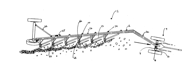
Figure 1 is a plan view of the rake of the instant application.
Figure 2 is a side sectional view of the rake of figure 1.
Figure 3 is a front view of the rake of figure 1.
Figure 4 is a front view of one of the rake wheels.
Figure 5 is a side view of the rake wheels.
Figure 6 is a rear view of the rake of figure 1.
DESCRIPTION OF THE PREFERRED EMBODIMENT
Having reference to the accompanying drawings, there is shown
the rake 1.
20S0~13
The rake 1 comprises an elongate frame 2 wherein the front
section 2a is angled inwardly at an angle of 37 on the near side,
with respect to the rear section 2b.
At the front section of the frame 2 there is provided a wheel
assembly 4. This wheel assembly 4 is connected to the frame 2 in
such a manner that the frame 2 may be lowered or raised so as to
position the tines 5 on the rake wheels 6 into or out of contact
with the ground. A circular bore (not shown) is defined at the
front of the frame 2a extending longitudinally therethrough.
There is provided a front axle housing 8 having vertically
disposed end plates 10 and a forwardly extending horizontal base
plate 12. The tyres 14 and wheels 16 are mounted on an axle 18
which rotates within the housing 8. A central circular bore is
formed in the axle housing 8 and receives a pipe 20 having a
circumferential flange 22. A vertical rod 24 extends through the
pipe 20. Slidably mounted on the rod 24 there is a second pipe
(not shown) , which is in turn encircled by a third pipe 26. This
latter also has affixed to it an attachment plate 28.
The rod 24 extends slidably through the above-mentioned
circular bore formed at the front of the frame. A hydraulic
cylinder 30 is affixed at one end to the attachment plate 28 and at
its other end to the frame 2. Thus, actuation of the cylinder 30
will raise or lower the frame relative to the wheel assembly 4. In
front of the rod 24 there is positioned a support bar 32. The bar
32 is interconnected to the rod 24 at its upper end by means of a
plate 34. At its lower end, the support bar 24 rest on the plate
12. Secured to the front end of plate 12 is a yoke 36 through
which extends a roll bar 38. The drawing bar 40, for connection
with the tractor, is secured to the yoke 36.
Having reference to figure 6 wherein the rear wheel assembly
42 is detailed. Whilst similar in structure to the front wheel
assembly 4, in being provided with hydraulic raising and lowering
means, nevertheless there exist certain differences.
There is provided the axle housing 44. The farside wheel 46
is conventionally mounted perpendicularly to the vertical plate 48
2060813
mounted at the edge of the housing 44. The wheel 46, tyre ,14
hub 16 are mounted on the axle 8.
The nearside wheel 47, however, is mounted at an angle of 15
to the vertical. The end plate 49 on the nearside like-wise is
angled at 15. Through a bore in the plate 49 extends the axle 8.
A central circular bore (not shown) is formed in the axle housing
44 and receives a pipe having a circumferential flange. A vertical
rod 50 extends through the pipe. Slidably mounted on the rod there
is a second pipe, which is in turn encircled by a third pipe.
This latter also has affixed to it an attachment plate 52.
The rod 50 extends slidably through the above-mentioned
circular bore formed at the rear of the frame. A hydraulic
cylinder 54 is affixed at one end to the attachment plate 52 and at
its other end to the frame 2b. Thus, actuation of the cylinder
will raise or lower the frame relative to the wheel assembly.
Behind the rod 50 there is positioned a support bar 56. The bar 56
is interconnected to the rod 50 at its upper end by means of a
plate 58. At its lower end, the support bar 56 rests on the plate
60. A support strut 62 extends between the rear axle housing 44
and an outwardly extending plate 65 mounted on the frame 2.
The rake wheels 6 are mounted on the frame 2 as follows.
A support arm 66 is secured to the frame extending
perpendicularly therefrom. Mounted at the outer end of said
support arm 66 is a pipe 68. A gusset 70 is secured to the pipe 68
and is adapted to rotatably receive the end of a bent rod 72. At
its inner end, the rod 72 is bent at an angle of 27 where it is
rotatably received in a bushing 74 which bushing is mounted through
the frame 2.
The rake wheel 6 is mounted on the outside of the pipe 68 by
means of a roller 76 . The positioning of pipe 68 at an angle of
18to the rod and bending of the rod result in the rake wheels 64
being at a 45to the rear section of the frame.
On the outer circumference are placed a plurality of spaced
apart tines 5. The tines 5 extend tangentially from the periphery
extending at an angle of 20 relative to the diameter. For a rake
2060813
wheel of 39 inches diameter the tines would be spaced 41/16 inches
apart.