Note: Descriptions are shown in the official language in which they were submitted.
2~~~~~2
-1-
IMPROVED DIE TOOLING FOR METAL WORKING
BACKGROUND OF THE INVENTION
This invention relates to metal working
operations) and, more particularly) to die tooling
with improved resistance to wear.
Many metallic articles are formed to their
final shapes and sizes by metal working techniques.
In one such technique, a thin metal article is
formed from a sheet or coiled strip metal workpiece
using a metal forming die. The die is another piece
of material having a preselected shape that aids in
the forming of the workpiece into its intermediate
or final shape. Sheet workpieces are commonly
formed by forcing the sheet into a female die using
a male die.
Some of the die forming operations involve
large tonnages of metal workpieces and produce
familiar products. For example, most automobiles
have metallic body panels. To fabricate those
panels, flat pieces of metal sheet are formed by
placing the starting sheet over a female die, and
then forcing the sheet into the female die with an
appropriately shaped male die. The resulting part
has the complex shape of the body panel.
The life of dies is normally limited by wear
that causes changes in their dimensions and thence
to the dimensions of the finished parts. As each
part is formed) the friction between the sheet
workpiece and the die removes some small amount of
material from the die. Eventually, the die is so
changed in dimension that the final products do not
meet the dimensional standards.
In production operations, the dies are made
from specialty steels or other ferrous-alloy
205~~~~
=2-
materials that are very hard and wear resistant
compared with the articles produced using these
dies. Such dies can be used to form thousands of
individual parts. These dies used in production
operations are typically expensive to manufacture
for a number of reasons, including the difficulty in
machining hard materials and the need to perform
extensive surface treatments.
There is an economic incentive in the
manufacturing industry to replace expensive
ferrous-alloy tool and die materials with less
expensive non-ferrous materials. These non-ferrous
materials can be zinc-based or aluminum-based metals
or even non-metallic materials such as plastic or
epoxy. The problem, however) is that all of these
non-ferrous materials exhibit reduced wear life
compared to ferrous materials. The use of
non-ferrous materials has therefore been limited to
prototype fabrication or limited production runs
where it is not necessary that the die perform to
produce thousands of parts. For the non-ferrous die
materials to have production applications,
techniques must be developed to extend their wear
life.
There is therefore a continuing need for
improved non-ferrous die materials, which are
inexpensive and have acceptable wear-life
characteristics. The present invention fulfills
this need, and further provides related advantages.
SUMMARY OF THE INVENTION
The present invention provides improved
non-ferrous die materials and dies for use in metal
working operations. The die materials and dies of
the invention are less subject to wear than are
- 3 -
prior non-ferrous die materials and dies, and therefore
have longer lives in the sense that more parts can be
produced before replacement of the dies is required.
One aspect of this invention is as follows:
A process for making a coated material-working tool
having a preselected shape, comprising the steps of:
furnishing a substrate having the preselected shape
of a material-working tool;
coating the substrate with a coating of a silicon-
modified organic material; and
implanting the coating with a sufficient number and
energy of inert gas atoms to transform the silicon-
modified organic material at least in part to a silicon
carbide-containing coating.
In this process) the substrate is formed to
the desired die shape and dimensions by a
conventional technique such as machining. The
substrate is preferably a known type of non-ferrous
die material such as a filled epoxy or a zinc-based
metallic alloy. The surfaces of the die most
subject to wear are coated with a silicon-modified
organic material such as an organic silane) which
also contains hydrogen and carbon. The coating is
preferably thin) Qn the order of 200 nanometers
thick (or, alternatively stated) 2000 Angstroms}.
Because the coating is so thin, the original
substrate can be machined to essentially the same
dimensions as in conventional practice wherein no
coating is used, an important convenience for the
die makers. After the coating is applied) it is
implanted (bombarded) with inert gas atoms,
preferably provided as ions, of sufficient energy
and of a sufficient total dose to alter the organic
material to remove hydrogen. The use of ion
implantation to transform the applied coating into a
coating having different properties than the
original coating is known as ion-beam mixing) ion
~;, :,,~
2Q~~~~2
=4-
beam enhanced deposition (IBED)) or ion beam
assisted deposition (IBAD). Examples of acceptable
ion implantation techniques to transform the coating
are direct implantation, such as described in US
Patent 3,900,630, or plasma source ion implantation)
such as described in US patent 4,764,394. This
implantation treatment transforms the coating to a
silicon carbide-containing layer) which normally has
some hydrogen remaining therein. The silicon
carbide-containing layer improves the wear
resistance of the die, thereby increasing its life
during service.
In another approach within the scope of the
invention, a process for working a workpiece using a
tool having a preselected shape comprises the steps
of furnishing a substrate formed of a zinc-based
alloy and having the preselected shape of a material
working tool; and implanting nitrogen, preferably in
the form of nitrogen ions, into the surface of the
substrate to harden the surface of the substrate.
This technique, applicable to zinc-based
alloys containing copper and aluminum as alloying
ingredients) is practiced by preparing a substrate
to the desired die shape and dimensions. No coating
is required. Nitrogen ions are implanted into the
surface to modify the surface of the die so that it
is more wear resistant and has a longer life than an
untreated die.
The approach of the invention has the
important advantage that the surfaces of the dies
are treated to obtain improved performance after
final machining, and without the need to raise the
temperature of the machined die significantly.
Other surface treatments to improve die performance
typically require that the die be heated to at least
several hundred degrees during the surface treatment
process, and then cooled to ambient temperature.
- 5
Such temperature changes during surface treatment
can cause the die to warp from its desired shape due
to stresses in the die and to uneven heating and
cooling. If the die material itself contains an
organic component, as in the case of a filled
polymer such as an epoxy) surface treatments may
simply not be possible because the organic component
cannot tolerate the temperature required for the
surface treatment. Another important advantage of
the approach of the invention is that it introduces
little or no significant dimensional changes into
the implanted article.
Other aspects of this invention are as
follows:
A coated material-working tool that has
extended functional life, comprising:
a substrate having the preselected shape of a
material working tool; and
a coating on the surface of the substrate
consisting essentially of silicon, carbon, and hydrogen
atoms with the silicon and carbon atoms in an atomic
ratio of about 1 to 1.
A process for treating a material-working
tool of a preselected shape, comprising the steps of:
furnishing a substrate formed of a zinc-based
alloy and having the preselected shape of a material
working tool; and
implanting nitrogen into the surface of the
substrate to harden the surface of the substrate.
Thus, the present invention provides an
advance in the art of metal working dies. Other
features and advantages of the invention will be
apparent from the following more detailed
description of the preferred embodiments, taken in
conjunction with the accompanying drawings, which
illustrate) by way of example) the principles of the
invention.
- 5a -
BRIEF DESCRIPTION OF THE DRAWINGS
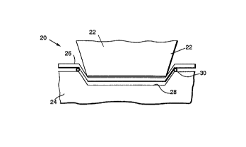
Figure 1 is a schematic side elevational view
of a male/female set of metalworking dies during a
forming operation;
Figure 2 is a greatly enlarged side
elevational view of a portion of a die bead with a
coating of a silicon-modified organic material;
Figure 3 is a side elevational view similar
to Figure 3) after completion of the
ion-implantation treatment; and
Figure 4 is a greatly enlarged side
elevational view of a die bead after nitrogen
implantation.
-6_
DETAILED DESCRIPTION OF THE INVENTION
By way of background, Figure 1 illustrates a
die set 20 having a male die 22 and a female die 24,
at an intermediate stage of the fabrication of a
thin sheet workpiece 26. The female die 24 has a
die surface 28 of the preselected final desired
shape of the workpiece 26. The male die 22 has a
corresponding preselected shape to force the
workpiece 26 into the female die 24 until the
workpiece 26 reaches that final desired shape as
defined by the dies.
Frictional wear occurs on all faces of the
dies 22 and 24 that contact the workpiece 26.
Lubricants are typically applied to these faces to
reduce friction and thence wear, but wear still
occurs. After a number of forming operations with a
succession of workpieces, the wear-induced
dimensional changes of the tool may become so large
that the finished part is no longer within its
required tolerances. The dies are then refurbished
or scrapped) either operation being expensive.
As may be seen by inspection of Figure 1 and
as known from die forming experience, the greatest
incidence of wear-induced damage typically occurs at
a die bead 30 wherein the workpiece enters the
female die 24. The combination of bending and
frictional forces produce the most severe damage at
the die bead 30. The present invention is therefore
most beneficially utilized in conjunction with
protection of the die bead 30) although it is
applicable to other regions of the dies 22 and 24.
Figures 2-4 illustrate the curved die bead 30
in greatly enlarged form as a preferred portion of
the die set 20 to receive the processing of the
invention. As the initial step of the present
2~~~9~2
approach, the die bead 30 and the remaining portions
of the dies 22 and 24 are furnished in their final
preselected shape and size for the forming
operation. The ability to place the dies into their
final form at the outset of the process is important
for two reasons. First, it permits the present
invention to be used in conjunction with established
die structures. Second, no expensive post-treatment
machining operations are required. By contrast, one
of the reasons that other die treatments are so
expensive is that they require initial care to
produce a die for surface treatment and then
precision final machining of the die after the
treatment is complete. The die shape and size must
often be specially selected for the treatment
process, and then the treated die is machined to the
final desired shape after the surface treatment.
The present approach requires no such final
machining) and indeed such final machining of the
die surfaces is not permitted because it would
disrupt the thin treated layer.
The bead 30 includes a substrate 32 formed of
a die material. The substrate may be a metal such
as a zinc-based alloy containing copper and
aluminum, or a nonmetal such as a filled epoxy
polymer. The substrate 32 is coated with a coating
34 of a silicon-modified organic material, as shown
in Figure 2. The coating 34 is preferably applied
by dipping the substrate 32 into a solution of the
silicon-modified organic material dissolved in an
appropriate solvent such as toluene, resulting in a
coating thickness of from about 100 to about 250
nanometers, most preferably about 200 nanometers.
After the ion implantation treatment, a coating of
this thickness provides improved die life. This
coating is so thin that it is not necessary to make
an allowance for it in machining the dies to their
-g_
final preselected shape prior to coating. That is)
if the coating were much thicker, on the order of
thousandths of an inch) it might be necessary to
make allowance for the coating thickness when the
dies were machined, so that they could not be
machined to their preselected final shapes and
sizes. Conventional machining techniques are not
accurate to dimensions within the range of a few
hundred nanometers) and therefore the dies can be
machined to their final preselected shape and size
without regard to the fact that they will
subsequently be coated.
The coating material is a silicon-modified
organic material such as an organic silane. (Under
some very strict definitions) an "organic" material
can contain only carbon) oxygen, and hydrogen. In a
less restrictive usage that is adopted herein, the
"organic" material contains these elements and
others, and in particular is modified by the
addition of silicon bonded to the basic molecule.)
A preferred silicon-modified organic material is
poly (dimethylsilane-co-methylphenylsilane)) which
contains carbon) silicon) and hydrogen in an atomic
ratio C:Si:H of 9:2:14. In a preferred application
approach, this coating material is dissolved in a
solvent such as toluene and the solution filtered.
The die material, such as the bead 30, is dipped
into the filtered solution and dried.
The coated bead is implanted with energetic
inert gas atoms) preferably in the form of ions
(which are atoms that have been ionized) of a
sufficient energy and total dose to transform the
coating into a predominantly silicon
carbide-containing layer 36, illustrated in Figure
3. The preferred inert gas is neon, as an atom or
an ion Ne+) although other inert gases such as
argon can also be used. The inert gas may be
-9-
~a~a~'~~
provided as an ion by using an ion implantation apparatus
of any conventional mode of operation and type. For
example, the ion implantation can be by direct
implantation, such as described in US Patent 3,900,630,
or plasma source ion implantation, such as described in
US Patent 4,764,394. Any acceptable energy may be used,
with energies in the 50-300 thousand electron volt (KeV)
range preferred. A presently preferred energy is 270
KeV. The total dose may vary, but is typically in the
l0 range of about 1014 - 101' ions per square centimeter. A
presently most preferred dose is about 4 x 1O14ions per
square centimeter for a 200 nanometer thick coating 34.
The mechanism of surface improvement is not known
with certainty, and the inventors do not wish to be bound
by the following possible explanation. It is presently
believed that the ion implantation transforms the organic
material toward a silicon-to-carbon atom ratio of 1:1,
and reduces the content of hydrogen, nitrogen, oxygen,
and other elements that might be present in the initial
coating 34. Such transformations are known, and are
described, for example, in the publication of T.
Venkatesan, "High Energy Ion Beam Modification of Polymer
Films", Nucl. Instr. And Methods in Phys. Res., Vol.
B7/8, pages 461-467 (1985). However, it has not been
previously known to utilize the technique in conjunction
with the preparation of die tooling.
After the die or die part has been implanted with
ions as described, it is assembled into the die set 20. A
workpiece is then die formed using the approach described
previously. No post-implantation machining of the wear
surface of the die bead is performed, nor could any such
machining be performed
2~~fl9~2
-10-
because of the possibility of removing the thin
treated layer. Nevertheless, the die bead retains
its required dimensions from the machining prior to
implantation to be effective for forming operations.
One of the useful non-ferrous die materials
is a zinc-based alloy containing copper and
aluminum. A preferred composition, in weight
percent, is 0-10 percent aluminum) 0-20 percent
copper, balance zinc, but containing at least some
aluminum or copper. This die material may be
treated by the approach dust described) or by an
approach wherein no coating is used and the
implanted ion is nitrogen rather than an inert gas
ion.
Figure 4 illustrates a die bead 30 formed of
the zinc-based alloy. Under the second approach,
nitrogen atoms in the form of ions are implanted
into the surface of the die part, to form an
implanted region 38. The implanted region 38 is not
a separate layer that is applied to the surface, but
is instead a treated portion of the part that has
been previously machined to its preselected shape.
The preferred energy of the ions during implantation
is from about 50 to about 150 KeV) with 135 KeV
presently most preferred. The preferred total dose
is from about 1016 to about 101$ ions per square
centimeter) with a dose of about 1018 ions per
square centimeter presently most preferred. The die
part is then used in a metal working operation such
as that depicted in Figure 1. No post-implantation
machining of the wear surface of the die bead is
performed, nor could any such machining be performed
because of the possibility of removing the thin
treated layer. Nevertheless, the die bead retains
its required dimensions from the machining prior to
implantation to be effective for forming operations.
The mechanism of die surface improvement for
-11-
the nitrogen-implanted zinc-based alloy is not known
with certainty. It may be a chemical reaction to
form a nitride, straining of the surface layers by
the implanted ions, or a combination of the two.
Some chemical reaction is likely, as the benefits of
the process are specific to the use of nitrogen ion
implantation.
The following examples are intended to
illustrate aspects of the invention, and should not
be taken as limiting of the invention in any
respect.
Example 1
An epoxy block was machined to a preselected
die bead shape and size required for the forming of
a workpiece into a part) and was not formed either
oversize or undersize to account for a surface
treatment coating.
A coating mixture was prepared by mixing five
parts by weight of poly (dimethylsilane-co-methyl
phenylsilane) and 400 parts by volume toluene. The
mixture was stirred overnight and then filtered
through a series of filters from 25 micrometers down
to 0.1 micrometer pore size. The filter bead was
dip coated with- a single dipping in the solution,
dried at room temperature) and then dried at about
50oC in vacuum. The thickness of the dried layer
was estimated to be about 200 nanometers by
Nano-Spec measurements. The coated die bead was ion
implanted with neon ions at an energy of 270 KeV and
a total dose of about 4 x 10¹⁴ ions per square
centimeter. The coating remained adherent to the
substrate.
-12-
Example 2
Example 1 was repeated, except that the total
dose of neon ions was about 1016 per square
centimeter. The coating remained adherent to the
S substrate.
Example 3
The treated die bead of Example 1 was
subjected to a standard harsh draw test wherein a
piece of sheet metal is drawn, across the surface.
The drawing test was repeated six times before there
was an indication of the onset of wear on the
surface of the treated draw bead. For comparison,
an identical but untreated draw bead was tested in
the same test. It showed significant wear after
only one draw procedure.
The draw tests for the treated and untreated
die beads were continued for a total of nine draws)
and the surfaces were inspected. The treated draw
bead had a much smoother surface at the completion
of nine draws than did the untreated draw bead.
Example 4
The process of Example 1 was repeated, except
that the die bead substrate was replaced with a
block formed of a metallic zinc-based material
having a composition, in weight percent) of 0-10
percent aluminum, 0-20 percent copper, balance
zinc. The total dose of neon ions was about 1015
per square centimeter. The coating remained
adherent to the block.
-1.3-
Example 5
The process of Example 4 was repeated on two
other specimens, except that the total dose of neon
ions was 1016 per square centimeter in one case
and 101 per square centimeter in the other case.
Example 6
The block specimens of Examples 4 and 5
having neon doses of 1015, 1016, and lOl~ions
per square centimeter were tested for wear
resistance using an enhanced Falex block-on-ring
wear test and a testing pressure of 4000 pounds per
square inch. An untreated specimen was used as a
basis for comparison. The specimen having a dose of
1015 ions per square centimeter had a reduction in
wear rate of 1.4 times, and the specimen having a
dose of 1016 had a reduction in wear rate of 1.2
times) as compared with the untreated specimen
tested in an identical manner. The specimen having
a dose of 101 ions per square centimeter had the
same wear rate as the untreated specimen.
Example 7
A block was prepared from the zinc-based
alloy having a composition in weight percent of 0-10
percent aluminum) 0-20 percent copper, balance
zinc. Atomic nitrogen ions were implanted into the
block at ambient temperature with an energy of 135
KeV and a dose of 1018 ions per square
centimeter. An identical block was left untreated.
Example 8
The blocks of Example 7 were tested in the
-14-
block-on-ring wear test apparatus discussed under
Example b. The untreated block was tested at a
loading of 4000 pounds per square inch. The treated
block tested at this same pressure exhibited a
S completely unexpected wear rate reduction of 74
times as compared with the untreated block. The
same treated block was then tested at a loading of
12,000 pounds per square inch, and even at three
times the loading exhibited a wear rate reduction of
1.5 times compared to the untreated block.
The approach of the invention provides an
approach for improving the wear performance of die
tooling with minimal cost. Although particular
embodiments of the invention have been described in
detail for purposes of illustration) various
modifications may be made without departing from the
spirit and scope of the invention. Accordingly, the
invention is not to be limited except as by the
appended claims.