Language selection

Search

Patent 2061058 Summary

Third-party information liability

Some of the information on this Web page has been provided by external sources. The Government of Canada is not responsible for the accuracy, reliability or currency of the information supplied by external sources. Users wishing to rely upon this information should consult directly with the source of the information. Content provided by external sources is not subject to official languages, privacy and accessibility requirements.

Claims and Abstract availability

Any discrepancies in the text and image of the Claims and Abstract are due to differing posting times. Text of the Claims and Abstract are posted:

  • At the time the application is open to public inspection;
  • At the time of issue of the patent (grant).
(12) Patent: (11) CA 2061058
(54) English Title: GRAVITY ORIENTATION DEVICE
(54) French Title: DISPOSITIF D'ORIENTATION PAR GRAVITE
Status: Expired
Bibliographic Data
(51) International Patent Classification (IPC):
  • E21B 47/02 (2006.01)
  • G01C 9/12 (2006.01)
(72) Inventors :
  • GENDRON, ALAIN (Canada)
  • SENECAL, PIERRE (Canada)
(73) Owners :
  • NORANDA INC. (Canada)
(71) Applicants :
(74) Agent: BERESKIN & PARR LLP/S.E.N.C.R.L.,S.R.L.
(74) Associate agent:
(45) Issued: 1994-12-13
(22) Filed Date: 1992-02-14
(41) Open to Public Inspection: 1993-08-15
Examination requested: 1993-02-10
Availability of licence: N/A
(25) Language of filing: English

Patent Cooperation Treaty (PCT): No

(30) Application Priority Data: None

Abstracts

English Abstract


A gravity orientation device comprises a
cylindrical casing, a shaft rotatably mounted in the
casing along the longitudinal axis thereof and having
pointed ends contacting bearing surfaces located in the
ends of the casing, an encoder mounted within the casing
and having a fixed portion secured to the casing and a
rotary portion secured to the shaft, and a weight pendulum
mounted on the shaft for rotation around the shaft under
the influence of gravity.


Claims

Note: Claims are shown in the official language in which they were submitted.


WHAT IS CLAIMED IS:


1. A gravity orientation device comprising:
a) a cylindrical casing:
b) a shaft rotatably mounted in said cylindrical casing along a longitudinal
axis of the cylindrical casing and having pointed ends contacting bearing surfaces
located in ends of said casing, the shaft rotating a full 360° at a maximum angle
of inclination of the longitudinal axis of the casing nearly 90° from horizontal;
c) an encoder mounted within said casing and having a fixed portion
secured to said casing and a rotary portion secured to said shaft; and
d) a weight pendulum mounted on said shaft for rotation around the shaft
under influence of gravity.


2. A gravity orientation device as defined in claim 1 wherein
the encoder is a digital encoder capable of sending an output pulse at each half
degree or less of rotation of the shaft.


3. A gravity orientation device as defined in claim 1 wherein
the pointed ends of said shaft are journalled in bearing surfaces mounted in
tension screws which are adjustable to minimize friction of the shaft.


4. A gravity orientation device as defined in claim 1 wherein
said pendulum is weighted with mercury.


Description

Note: Descriptions are shown in the official language in which they were submitted.


205105~


GRAVITY ORIENTATION DEVIOE

This invention relates to a device for
monitoring the angle of rotation of a probe with respect
to gravity, more particularly the angle of rotation of a
probe suspended from a cable in a borehole, with respect
to gravity.
Many devices such as gyroscopes, inclinometers
or gravity potentiometers are used to determine the angle
of rotation of a probe in a borehole. However, each of the
above instruments has its own limits: an inclination angle
of +45 maximum, a maximum rotation of 350, drifting of
a few degrees with time, etc..
It is the object of the present invention to
provide a simple device for monitoring the angle of
rotation of a probe suspended from a cable over an angle
of 360, at a maximum angle of inclination of nearly 90
from the horizontal.
The gravity orientation device, in accordance
with the present invention, comprises a cylindrical
casing, a shaft rotatably mounted in such casing along the


.
7~

2~10~8


longitudinal axis of the casing and having pointed ends
contacting bearing surfaces located at the ends of such
casing, an encoder mounted within the casing and having a
fixed portion secured to the casing and a rotary portion
secured to the shaft, and a weight pendulum mounted on the
shaft for rotation with the shaft under the influence of
gravity.
The encoder is preferably a digital encoder
capable of sending an output pulse at each half degree or
less of rotation of the shaft.
The pointed ends of the shaft are preferably
journalled in bearing surfaces mounted in tension screws
which are adjustable to minimize friction of the shaft.
The pendulum is preferably weighted with
mercury.
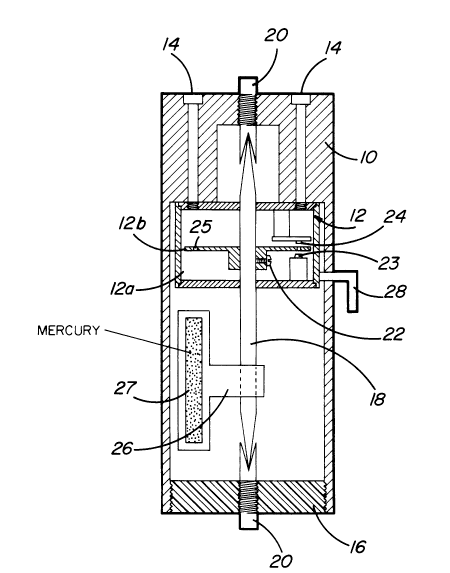
The invention will now be disclosed, by way of
example, with reference to the accompanying drawing which
illustrates a preferred embodiment of a gravity monitoring
device.
Referring to the drawing, there is shown a
cylindrical casing 10 which is designed to receive and
hold in place an encoder 12 which is secured to one end of
the casing by means of screws 14. The other end of the
casing is closed by an end piece 16. A shaft 18, having
both ends machined to a fine angle, is passed through the
center of the encoder. The pointed ends of the shaft

3 20610~

contact suitable bearing surfaces made of hard metal
located in the ends of the casing. The bearing surfaces
are preferably in the form of tension screws 20 which are
adjustable to minimize friction of the shaft. The encoder
is a conventional device, such as the one sold by Hewlett-
Packard under Serial Number HEDS-5310. It comprises a
fixed portion 12a which is secured to the casing and a
rotary portion 12b in the shape of a disc which is secured
to the shaft by means of a screw 22. A light source 23 is
provided inside the encoder on one side of the disc and a
suitable light sensor 24 on the other side of the disc.
The disc is provided with a plurality of equally spaced
holes 25 through which light from the source may impinge
upon the sensor during rotation of the disc. A weight
pendulum 26 is secured to the shaft for rotation therewith
and is sized to clear the inside wall of the casing during
rotation. A few grammes of mercury 27 is placed inside the
pendulum to well define the position of gravity.
The tension on the bearings is adjusted to have
a minimum friction with the pointed end of the shaft so
that the shaft will rotate a full 360 at a maximum angle
of inclination of the longitudinal axis of the casing of
nearly 90 from the horizontal.
In operation, the fixed portion 12a of the
encoder determines the position of the rotary portion 12b
of the encoder by sending a pulse through an output wire


2~610~


28 at each 0.5 or less of rotation of the shaft. An
electronic circuit board of conventional design may be
used to count the pulses and convert them to degrees of
rotation of the shaft.
The above orientation device has been developped
for detecting any angular deviation resulting from torsion
of a cable supporting a camera head assembly used in a
borehole as disclosed in Canadian Patent Application No.
2,041,873 filed May 6, 1991. However, it may be used in
other applications where a similar angular deviation could
be measured using gravity as a reference.

Representative Drawing
A single figure which represents the drawing illustrating the invention.
Administrative Status

For a clearer understanding of the status of the application/patent presented on this page, the site Disclaimer , as well as the definitions for Patent , Administrative Status , Maintenance Fee  and Payment History  should be consulted.

Administrative Status

Title Date
Forecasted Issue Date 1994-12-13
(22) Filed 1992-02-14
Examination Requested 1993-02-10
(41) Open to Public Inspection 1993-08-15
(45) Issued 1994-12-13
Expired 2012-02-14

Abandonment History

There is no abandonment history.

Payment History

Fee Type Anniversary Year Due Date Amount Paid Paid Date
Application Fee $0.00 1992-02-14
Registration of a document - section 124 $0.00 1992-09-18
Maintenance Fee - Application - New Act 2 1994-02-14 $100.00 1994-01-11
Maintenance Fee - Application - New Act 3 1995-02-14 $100.00 1994-12-09
Maintenance Fee - Patent - New Act 4 1996-02-14 $100.00 1996-01-17
Maintenance Fee - Patent - New Act 5 1997-02-14 $150.00 1996-12-19
Maintenance Fee - Patent - New Act 6 1998-02-16 $150.00 1997-12-23
Maintenance Fee - Patent - New Act 7 1999-02-15 $150.00 1998-08-31
Maintenance Fee - Patent - New Act 8 2000-02-14 $150.00 1999-12-24
Maintenance Fee - Patent - New Act 9 2001-02-14 $150.00 2001-01-25
Maintenance Fee - Patent - New Act 10 2002-02-14 $200.00 2002-02-11
Maintenance Fee - Patent - New Act 11 2003-02-14 $200.00 2003-01-27
Maintenance Fee - Patent - New Act 12 2004-02-16 $250.00 2004-02-02
Maintenance Fee - Patent - New Act 13 2005-02-14 $250.00 2005-02-11
Maintenance Fee - Patent - New Act 14 2006-02-14 $250.00 2006-02-01
Maintenance Fee - Patent - New Act 15 2007-02-14 $450.00 2007-01-29
Maintenance Fee - Patent - New Act 16 2008-02-14 $450.00 2008-01-28
Maintenance Fee - Patent - New Act 17 2009-02-16 $450.00 2009-02-03
Maintenance Fee - Patent - New Act 18 2010-02-15 $450.00 2009-12-15
Maintenance Fee - Patent - New Act 19 2011-02-14 $450.00 2011-02-08
Owners on Record

Note: Records showing the ownership history in alphabetical order.

Current Owners on Record
NORANDA INC.
Past Owners on Record
GENDRON, ALAIN
SENECAL, PIERRE
Past Owners that do not appear in the "Owners on Record" listing will appear in other documentation within the application.
Documents

To view selected files, please enter reCAPTCHA code :


To view images, click a link in the Document Description column. To download the documents, select one or more checkboxes in the first column and then click the "Download Selected in PDF format (Zip Archive)" or the "Download Selected as Single PDF" button.

List of published and non-published patent-specific documents on the CPD .

If you have any difficulty accessing content, you can call the Client Service Centre at 1-866-997-1936 or send them an e-mail at CIPO Client Service Centre.


Document
Description 
Date
(yyyy-mm-dd) 
Number of pages   Size of Image (KB) 
Claims 1994-12-13 1 28
Drawings 1994-12-13 1 22
Representative Drawing 1998-10-29 1 20
Abstract 1994-12-13 1 14
Cover Page 1994-12-13 1 15
Abstract 1994-12-13 1 14
Description 1994-12-13 4 112
Fees 2003-01-27 1 37
Fees 2002-02-11 1 38
Correspondence 2002-03-25 3 102
Correspondence 2002-05-07 1 15
Correspondence 2001-02-21 2 55
Fees 2004-02-02 1 35
Prosecution Correspondence 1993-02-10 1 28
Prosecution Correspondence 1994-06-02 2 41
Examiner Requisition 1994-05-18 1 53
Office Letter 1993-03-22 1 40
Office Letter 1994-06-22 1 15
PCT Correspondence 1994-09-28 1 37
PCT Correspondence 1993-09-21 1 25
Fees 2005-02-11 1 33
Fees 2006-02-01 1 45
Fees 2007-01-29 1 42
Fees 2008-01-28 1 42
Correspondence 2009-01-07 3 67
Correspondence 2009-01-19 1 12
Correspondence 2009-01-19 1 15
Fees 1996-12-19 1 68
Fees 1996-01-17 1 43
Fees 1994-12-09 1 39
Fees 1994-01-11 1 60