Note: Descriptions are shown in the official language in which they were submitted.
2~1086
JUICE EXTRACTOR
Field of the invention
The present invention relates to a method and an apparatus
for preparing juice from vegetables, fruits and the like, and
more particularly to an improved juice maker apparatus which
includes a pair of helical gears for crushing the raw material,
two screws connected concentrically to the helical gears, a
driving section for rotating the helical gears, a filtering sieve
surrounding part of the helical gears and the screws, and a
housing for supporting the driving section, the helical gears and
the filtering sieve.
Backaround of the invention
A juice maker apparatus is disclosed ln Korean Utility Model
~; Publication No. 91-4356 which was filed on Nay 9, 1989 by the
present appllcant. This device includes two helical gears for
crushing fruits or vegetables, screws connected respectively to
the shafts of the helical gears, a driving section for supplying
driving power to the hellcal gears, a filtering sieve surrounding
~;~ part of the helical gears and the screws, and a housing for
supporting the driving section, the helical gears and the
filtering sieve.
Since this juice maker uses the helical gears of usual form,
it ca~ extract the juice from a source material,but it is
difficult to crush the fibroid materials, i.e. the fiber of the
source material. FurtheF, the filtering sleve whlch is intended
: '
.
2 ~ 8 6
_o separate the juice from the dregs, i.e. the juice extracted
material, inadequately extracts juice from the dregs. In the
event complete extraction is attempted, the resulting juice
contains fibroid materials which reduce the eye pleasing
attractiveness of the juice.
Further, the manufacturing of the helical gears is a
time-consuming process, while there is encountered much
difficulty in machining the helical gears. Further, the
produced juice can be oxidized depending on t~he material of the
helical gears, and therefore, a need for the i~provement of the
helical gears came to be felt.
Further, if the working section consisting of the helical
gears, the filtering sieve and the housing is to be cleaned by
detaching it from the driving section, the detachment and a
re-attachment of it is difficult. Further, there is also
- required a means for closely contacting the two helical gears
together.
The present invention is intended to overcome the above
described disadvantages of the known juice maker.
Therefore it is the object of the present invention to
provide a juice maker which overcomes the disadvantages of the
prior art devices.
It is a further object of the present invention to provide
a juice maker which efficiently extracts juice from raw juice
containing material and separates the extracted juice from the
juice,é~tracted material and delivers the extracted juice and the
~uice extracted material to the outside of the housing to
facilitate access to the extracted juice and clean-up.
20~1086
It is a further object of the present invention to provide
a juice extractor which utilizes crushing and compression forces
to fully extract juice for raw juice containing material.
It is a further object of the present invention to provide
a method of extracting juice from juice containing material.
The juice making method according to the present invention
is capable of extracting nutrition from the fibroid materials
(fiber of source material) by crushing the fibroid materials
utilizing a pair of helical gears.
The juice making method includes the steps of: cutting the
raw material by means of the end portions of the teeth of one of
the gears, and inserting the cut material into the inter-teeth
space of the other gear; compressing the cut raw material within
the inter-teeth space; and crushing the cut raw materials
through the combined function of the end portion of the teeth of
one of the gears and pockmark portions of the fillet portions
of the other gear. Thus the fibroid materials are cru6hed, and
the nutrition contained in the fibroid materials are extracted
together with the juice.
~;~ 20 The foregoing has outlined some of the more pertinent
objects of the present invention. These objects should be
construed to be merely illustrative of some of the more pertinent
features and applications of the invention. Many other
beneficial results can be obtained by applying the disclosed
invention is a dif~erent manner or modifying the invention within
the s~c4~e of the disclosure. Accordingly, other objects and a
more thorough understanding of the invention may be had by
referring to the summary of the invention and the detailed
.. . . .
:
:, ~ .
20610~
lescription describing the preferred embodiment in addition to
the scope of the invention defined by the claims taken in
conjunction with the accompanying drawings.
SUMMARY ~F THE INVEN~ION
The juice extractor and method of the present invention is
defined by the appended claims with a specific embodiment shown
in the attached drawings. For the purpose of summarizing the
invention, the invention relates to an apparatus for extracting
juice from raw juice containing material and ~hich comprises a
housing for supporting the apparatus and including a raw juice
containing material inlet for permitting raw juice containing
material to pass therethrough. A pair of meshing helical gears
2,3 with each helical gear terminating in a tapered screw are
used. Each helical gear includes a plurality of teeth each of
which extend along the length of the helical gear and terminate
proximate the tapered screw. Each helical gear is rotatably
secured in the housing to enable in use raw juice containing
material to be supplied through the inlet of the housing to the
pair of meshing helical gears for crushing the raw juice
containing material to initially extract juice therefrom. In the
preferred embodiment both of the helical gears and the tapered
screw are made of stainless steel having about 3 to 4
bio-ceramic to prevent oxidation and decomposition of the juice
during contac't with the helical gears. A sieve 4 is operatively
posit~o~ed around the helical gears and each the tapered screws
-for enabling in use the filtering and draining away from the
helical gears and the tapered screws juice extracted by the
20610~6
lelical gears and the tapered screws. Preferably, the sieve is
branched 47,48 with each branch housing at least a portion of one
of the tapered screws, respectively, and with each branch of the
sieve having a terminal end with a discharge outlet formed
thereat to enable each the screw to further extract juice from
the crushed raw juice containing material by compressingly moving
the crushed juice containing material along one of the branch
portions of the sieve and toward one of the discharge outlets
formed in the sieve. An outlet disc 7 is positioned at each of
the terminal ends of each the discharge outlets with the outlet
disc tensioned in a~closed position. That is the outlet disc is
biased in a closed position to close off the discharge outlet.
Thus, in use, the tapered screw continually forces the crushed
material against the outlet disc which further extracts juice
from the crushed material until. Once enough pressure is exerted
against the outlet disc, the force tensioning the outlet disc in
j .~ .
the closed position give way and open th- discharge outlet to
enable the discharging of the juice extracted material from the
outlet of the housing. A power means 1 supplies rotational
output to the helical gears and the tapered screws.
Thus, upon powering the apparatus of the present invention
the raw juice containing material supplied through the inlet is
crushed and otherwise acted upon hy the helical gears to
initially extract juice while also being pushed along the heliaal
gears to one'of the tapered screws. At the tapered screw the
resul~ng material is pushed along by one of the tapered screws
where it is also compressed to further extract juice and is
finally discharged through one of the outlets formed in the
.
~0610~
~ieve.
Xt is preferred that the sieve which is operatively
positioned around each the tapered screw include large holes
proximate the helical gears, small holes proximate each discharge
S outlet of the sieve and with medium sized holes therebetween to
enable in use the juice extracted raw material to be
compressingly moved by each the screw toward the discharge outlet
while being retained within the sieve prior to being forced from
the discharge outlet while simultaneously allowing juice made
available by the compression to drain from the sieve operatively
positioned around eàch the tapered screw. Preferably the taper
of the sieve follows the taper of the tapered screws.
The teeth of the helical gear are elongated in structure as
illustrated in the figures described below. Further each of the
teeth of the plurality of teeth of each the helical gear are
preferably formed with a pressure angle of about 28 to 300 and
have an addendum and a deddendum which are equal to eàch other
to enable zero clearance between meshing teeth. Moreover each
tooth of the plurality of teeth of the helical gears preferably
includes an end surface 82 and a fillet portion 83 which are
provided with slightly rough surfaces and a plurality of
pockmarks in a direction perpendicular to the gear shaft to
provide in use enhanced juice extraction by further pulveri~ing
the raW juice containing material.
A blade 6 æeparates the juice from the juice extracted
mater~a~ (dregs) to enable collection of each outside of the
-housing~ This is particularly valuable where a lot of juice
containing raw material is to be processed. The blade has a
2~10~6
.irst side and a second side and is positioned proximate the
discharge outlets of the sieve to enable the juice extracted from
the juice containing raw material to flow on to the first side
of the blade and the juice extracted material discharged from the
discharge outlets formed in the sieve to flow on to the second
side of the blade thereby separating the juice and the juice
extracted material to enable separate collection thereof.
A tensioning means is preferred for variably tensioning the
pair of helical gears against one another to enable the helical
gears to separate, i.e. move against the tensioning means, when
a seed, or the like, enters between the helical gears to protect
the helical gears from damage. However, the tensioning means is
to force one helical gear toward the other helical gear, until
there is left no clearance between the teeth of said two helical
gea~s.
In one embodiment, the tensioning means includes each of the
helical gears terminating in a tapered screw having a shaft
extending axially from the helical gear and from the tapered
screw and with the shafts being rotatably secured in the housing.
A first and a second coil spring is tensioned against the shaft
extending axially from the helical gear and the shaft extending
axially from the tapered screw, respectively. A forcing means
tensions or forces each coil spring against the respective shafts
extending axially from the helical gear and from the tapered
screw. In another embodiment of the tensioning means, the
housing includes a pair of internally threaded apertures formed
therein to provide access to the shafts extending axially from
the helical gear and from the tapered screw, respectively. In
2Q~1~8~
chis embodiment, the forcing means is a pair of screws with one
of the screws being received in one of the internally threaded
apertures and with the remaining screw being received into the
remaining internally threaded aperture, such that upon rotating
the screws, the screws engage the coil springs, respectively,.and
tension the helical gears together.
In another embodiment of the tensioning means the forcing
means is a disc cam with a handle 151, a first stopper face 153
and a second stopper face 152 and with the disc cam being
pivotally secured to the housing so as to be in ;contact with the
coil spring such that in use upon pivoting the disc cam from a
first position with the first stopper face in contact with the
coil spring to a second position with the second stopper face in
contact with the coil spring, the coil spring goes from a non-
tensioned state to a tensioned state thereby tensioning thehelical gears together.
In a further embodiment, the tensioning means includes a
pair of rods having a first, second and mid portion with each mid
;~ portion of the rods being served to define a pair of parallel
sloped surfaces (inclined planes) and with the second portion of
each rod being in contact with one of the coil springs and
.
:: : secured in the housing against rotation and with the first
portion terminating in a handle, respectively. Thus, in use,
upon securing the first portion of the rod to the hou9inq and
~:~ 25 rotating eacX handle from a first position to a second position,
"
:: the ~ped surface of the first portion of the rod rotates
:
. against the sloped surface of thé second portion of the rod
~ pushihg the second portion of the rod against the coil spring
: 8
:
2~6~0~6
~uch that each coil spring is tensioned against one of the shafts
extending axially from the helical gear and from the tapered
screw, respectively.
The first portion of each of the rods is secured to the
housing by a cap with each cap having a hole formed therein for
receiving therethrough the handle of one of the shafts,
respectively.
In another embodiment of the present invention, the housing
is divided into a first section and a second section with the
first section including the power means and the second section
including the helic~al gears and with the first section being
separable from the second section. The separable structure
enables the cleaning of the ~econd section of the housing apart
from the first section of the housing. A coupling means is
utilized to operatively secure the first section of the housing
to the second section of the housing.
In one embodiment, the coupling means includes the first and
the second sections of the housing each including a terminal end
with each terminal end having a flange formed thereat. A locking
ring having a pair of clip portions with each clip portions
having an inner surface with a groove formed therein for
receiving into the grooves each flange of the first and the
second sections of the housing in a side-by-side arrangement.
A closing means secures the clip portions together such that in
use each flan~é is received into each groove o~ each alip portion
of th~ ~locking ring and forced together to thereby securely
-interconnect the first section and the second section of the
housing together for use in extracting juice. The clip portions
g
.. . . . .
2061~8fi
:ach have a first and a second end, with each of the first ends
of the clip portions being hinged together and with each of the
second ends of the clip portions further including a bar hingedly
secured thereto, respectively, and with each bar having a
terminal end. The terminal end of one of the bars is hingedly
secured to the remaining bar pro~imate to its hinged securement
to the clip portion. Thus, in use, upon joining the flanges
together and positioning the grooves of the clip portions of the
locking ring to receive the ~oined flanges and manipulating the
remaining terminal end of the bar to tension the clip portions
against the flanges of the housing the first section and the
second section of the housing are secured together for use.
Preferably, each flange of each of the sections of the housing
is configured such that upon positioning the flanges together a
band having sloped sidewalls 242,262 is formed. Each of the
grooves formed in each of the clip portions has slopèd inner
sidewalls to receive therebetween the sloped sidewalls of the
band such that in use upon tensioning the clip portions together
the sloped inner sidewalls of the grooves forces together the
flanges to thereby further tension the first section and the
second sections of the housing together.
In another embodiment, the coupling means includes the first
and the second sections of the housings each having a terminal
end with one of the terminal ends of the first and the second
sections of ~he housing including a flange and the remaining
termi~ end of the first and the second sections of the housing
including a plurality of lugs radially extending therefrom. A
clip ring 202 having a "U" sectional shape with a first and a
20~0~6
~econd circumferential wall surface and with the clip ring
positioned on one of the first and the second sections in a
manner whereby the first circumferential surface blockingly
contacts the flange to prevent removal of the clip ring from the
housing. The second circumferential surface of the clip ring
includes a plurality of notches formed therein such that in use
the plurality of lugs of the housing are received through the
plurality of notches and upon partially rotating the clip ring
the plurality of lugs securely engage the second circumferential
surface thereby securing the first section of the housing to the
second section of the housing.
The present invention improves the helical gears, the
filtering sieve and the coupling portion of the housing from the
former juice maker.
The improved helical gears of the present invention are
formed with the deddendum and the addendum in the same size, so
that the clearance therebetween may be reduced to zero. Further,
a pressure angle of the helical gear is provided in 28 to 30,
thereby forming a special tooth form. In addition, each helical
gear is formed in a cylindrical shape, with a tapered screw at
its terminal end and a shaft joined to the ends thereof in an
integral form.
The improved filtering sieve of the present invention
consists of a helical gear filtering portion and a tapered sarew
filtering portion. The screw filtering portion is provided with
large~hoies, medium holes and small holes in the cited order, so
~hat the crushed materials should be contacted with decreasing
sizes of the holes as the pressure applied to the crushed
2~6~
.laterials increases. Meanwhile, the discharge hole for the dregs
is closed with a flat spring, in such a manner that the dregs
should be discharged only when the applied pressure reaches a
certain level. Further, the tooth portions of the helical gears
are made of stainless steel containing 3 to 4% of bioceramics,
so that the nutrition in the crushed fibroid materials should not
be destroyed. The foregoing has outlined rather broadly the more
pertinent and important features of the present invention in
order that the detailed description of the invention that follows
may be better understood so that the present contribution to the
art can be more fuLly appreciated. Additional features of the
invention will be described hereinafter which form the subject
of the claims of the invention. It should be appreciated by
those skilled in the art that the conception and the specific
embodiment disclosed may be readily utilized as a basis for
modifylng or designing other structures for carrying out the same
purposes of the present invention. It should also be realized
by those skilled in the art that such e~uivalent constructions
do not depart from the spirit and scope of the invention as set
forth in the appended claims.
DETAILED DESCRIPTION OF THE DRAWINGS
For a thorough understanding of the nature and objects of
the invention, reference should be had to the following detailed
description tàken in connection with the accompanying drawings
in whi~h
Figure 1 schematically illustrates the external structure
of the juice maker according to the present invention;
12
20~10~6
Figure 2A illustrates the coupling between the two helical
gears and the filtering sieve;
Figure 2B is a side view showing the relation between the
helical gears and the filtering sieve;
Figure 3A is a sectional view of the helical gear according
to the present invention;
Figure 3B is a sectional view taken along the line A-A of
the helical gear of Figure 3A;
Figure 3C is a sectional view taken along the line B-B of
. ~:
the helical gear of Figure 3A;
Figure 4 illustrates the end portions of the screw portion
of the helical gear;
Figure S illustrates the filtering sieve according to the
present invention;
Figure 6 is a perspective view showing the discharge
portion of the filtering sieve;
Figure 7A illustrates the coupled state of the helical gears
in order to show the method of the present invention;
Figures 7B, 7C, 7D and 7E illustrate the process of crushing
the raw materials;
; Figure 8 illustrates the shape of the teeth of the helical
gears;
: Figure 9 illustrates the coupling and the close contact
: between the helical gears and the housing;
Figure iOA illustrates one embodiment of the tensioning
means,,~l-
- Figure lOB is an exploded perspective view of a part of the
second embodiment of the tensioning means;
13
. ~ ~: ' .. '
, :
.
''" '
.
2051~6
Figures llA and llB illustrate another embodiment of the
tensioning means;
Figure 12 is an exploded perspective view of the tensioning
means;
Figure 13 is a perspective view of the coupling portion of
the juice maker;
Figure 14 is a sectional view of a part of the coupling
portion of the juice maker;
Figure 15 illustrates the operation of the coupling portion
of the juice maker;
Figures 16A and-l6B are perspective views of the clip ring;
Figure 17 is a perspective view of the leading end portion
of the working section housinq;
Figure 18 is a plan view of a semi-circular adjusting
plate;
Figure 19 is a sectional view of a part of the clip; and
Figures 2OA and 2OB are plan views, in which Figure 2OA
illustrates the state before fastening, and Figure 20B
illustrates the state before disassembling.
Similar reference characters refer to similar parts
throughout the several views of the drawings.
;::
DESCRIPTION OF THE PREFERRED EMBODIMENT
The constitution, operation and effects of the present
invention wil~ be described in detail referring to the attached
drawi~ s.
Figure 1 illustrates the overall external appearance of the
juice maker according to the present invention, and, as shown in
14
2051~8~
his drawing, a working section is connected to a driving section
l. The working section is constituted such that helical gears
are accommodated within a housing 12. Raw materials entering
through an inlet 11 are crushed by the hèlical gears, and the
dregs are pushed toward the right side of a blade portion 6 of
the filtering sieve, while the juice is let to flow toward the
left.
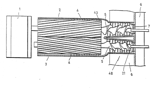
Figure 2A is a schematic sectional view showing the helical
gears and the filtering sieve in order to illustrate the juice
maker of the present invention.
The driving section 1 includes a motor and reduction gears !
for supplying rotating driving power to one of the helical gears.
A screw 5 extends from the position where the helical gear
portion of the helical gear ends, and this screw takes a tapered
form away from the helical gear. That is, the diameter of the
screw decreases from the helical gear.
A filtering sieve 4 surrounds the screw portion and the
helical gear portion of the helical gear. The filtering sieve
is provided with a plurality of holes on a portion 43 which
surrounds the helical gear portion, while the two filtering
portions 47,48 which surround each screw portion, respectively,
are provided with large, medium and small holes.
Below the filtering portion, a blade portion 6 is
positioned. The biade portion is disposed closely to a dregs
path and a j~ce path which are for transferring the dregs and
juice~fter separation of them.
Surrounding the filtering sieve, there is installed a
housing 12 which defines the position of the filtering sieve and
.
, ~ ' .
. ...
'
2 0 ~ 6
supports the shafts of the helical gears, as well as making it
possible to attach and detach the helical gears and the
filtering sieve to and from the driving section.
The two helical gears mesh and rotate together to cut and
crush the raw materials between the teeth thereof. The inlet 11
for the raw materials is disposed above the helical gear portion,
and, when raw materials are fed into the inlet 11 they enter
between the two helical gears to produce a mixture of crushed and
cut raw juice containing material and extracted juice.
The mixture of the crushed and cut raw material is pushed
toward each of the-screws 5, and the juice is discharged to the
outside of the filtering sieve 4. The rest of the crushed
materials is further pushed by the two screws, and at the same
time, additional juice is discharged to the outside through the
filtering sieve. Meanwhile, the dregs are further compressed,
and, when the compressing force exceeds a certain level, they are
discharged to the outside through the discharge outlet formed in
the sieve.
Figure 2B illustrates the filtering sieve in a vertical
sectional view for clarity of the illustration. In the drawing,
the clrcular disc 7 for the discharge outlet is illustrated at
Figure 6 in a perspective view. This disc can be fitted to the
filtering sieve by means of a disc securing section 41, and its
detachment from the filtering sieve can also be conveniently
carried out.
The juice which is discharged through filtering sieve flows
down the left side of the blade portion 6, while the dregs are
discharged through the release outlet 71 which is formed in the
16
20~10~6
~ircular disc 7, to the right side of the blade portion 6.
Figure S illustrates the filtering sieve 4 with the
filtering sieve 4 being provided with an opening 47 for receiving
the raw materials therethrough, and with a plurality of holes
formed to the right side thereof. Two screw filtering portions
47,48 extend from and branch frcm the helical gear filtering
portion 43. The screw filtering portions 47,48 are provided with
holes which gradually decrease in diameter toward the discharge
outlet. Such gradual reductions of the sizes of the holes is
provided because of`the difference in pressure which is applied
on the dregs as the dregs are being pushed by the screws to and
through the discharge outlet.
The end portions of the screw filtering portions 47,48 are
provided with a disc securing portion 41 for securing the
circular disc 7 thereat as shown in Figures 2A, 2B, and 6. The
disc 7 has a spring portion 71 and a hole 72 for accommodation
of the helical gear shaft 53. The securing portion 41 and the
circular disc have elastic structures, and therefore, when
forcibly pushed in, they are inserted, while, if they are
forcibly pulled out, they are detached. Thus, the circular disc
can be "press-fit" into an operable position in the sieve. The
reaæon for doing so is that the circular disc 7 has a spring
portion 71 which enables the dregs to be discharged when the
force holding the spring portion in a closed position is
overc~me. It is noted that the spring portion may have to be
-replaced if its tensioning ability is weakened, worn out, or if
the adjustment of the elasticity has to be performed to enable
' ' .
-- :
20~10~6
different dregs to be forced therefrom, i.e. prevent clogging of
the discharge outlet by some dregs.
Figure 3A is a sectional view of the helical gears. Figure
3B is a sectional view taken along the line A-A of Figure 3A,
and Figure 3C is a sectional view taken along the line B-B of
Figure 3A.
The helical gear consists of a cylindrical helical gear
portion 23 and terminates in a tapered screw. More specifically,
the helical gear consists of a first shaft portion 22, a helical
gear portion 23, a 'tapered screw portion 5 and a second shaft
portion 51. The helical gear portion 23 is made of stainless
steel containing 3 to 4 ~ bio-ceramic in order to prevent the
oxidation and decomposition of the juice during extraction.
Figure 4 illustrates the end portion 21 of the tapered
screw, on which a flat portion 54 is formed in an approximate
vertical posture relative to the shaft 53. The flat p'ortion 54
is provided with a convex rod portion 55 which extends
perpendicular to the flat portion 54, and which plays a role in
pushing out the dregs from the sieve.
Figure 8 illustrates the shape of the teeth of the helical
gear. The teeth 81 of the helical gear are formed with a
pressure angle of 28 to 30, and with the addendum and deddendum
being made equal each other so as for the clearance between them
to become zero. The end surfaces 82 and fillet portions 83 of
the'te'eth are provided with slightly rough surfaces, and are
'provided with a plurality of pockmarks in a direction
perpendicular to the gear shaft. Thus, upon rotation of the two
18
2~o~
.neshing helical gears,'there is no clearance between the teeth,
and therefore, the fibroid materials entering into the helic'al
gears must be crushed prior to being pushed out of the housing.
Figures 7A to 7E illustrate the meshing teeth during the
process of crushing the fibroid materials comprising the raw
juice containing material according to the present invention.
Figure 7A is a sectional view showing the meshed state of
the two helical gears. When raw materials to~be crushed, such
as vegetables, frui~s, cereals and the li~e, are fed through the
housing inlet 11, the raw materials pass through the opening 47
(which is disposed on the left of the filtering sieve
illustrated at Figure 5j into the contact portions of the two
helical gears. The end portions of the teeth of the helical
gears are rough and angular in order to cut and crush the raw
materials. The housing inlet 11 and the opening 47 in the sieve
ensure are first cut into small pieces by the meshing teeth.
Thereafter the cut and crushed raw materials are conveyed to the
inter-teeth space for further action.
As shown in Figure 7B, the inter-teeth space is open so that
the raw materials which are cut by the ends of tooth 36 and tooth
~'~ 27 should be introduced into the inter-teeth space.
Figure 7C illustrates a state in which the inter-teeth
space narrows as the helical gears revolve. The cut raw
materi'als are then squeezed to the extent of the reduction of the
'inter-teeth space to extract juice therefrom.
Figure 7D illustrates a state in which the raw materials are
19
.. .
.. . .
... .
~ .
... . . .
20~10~
ufficiently squeezed, and most of the juice is separated out,
with only the fibroid materials remaining in the inter-teeth
space.
Figure 7E illustrates a state in which the remaining fibroid
materials are crushed between the end face 82 of the tooth and
the fillet 83. The end face of the tooth and fillet are provided
with a plurality of small depressions, i.e. pits or pockmarks,
in a rough form, and therefore, the fibroid materials are held
in the pockmarks. Further, when the two hellcal gears revolve,
the clearance between meshing teeth disappears, and therefore,
the fibroid materia'ls are crushed into fine particles by being
pressed between the end face and the fillet of the meshing teeth.
Under this condition, the fibroid materials may be crushed down
to a particle size of about 1 micron or less.
When the fibroid materials are crushed in the above
described manner, additional nutritional matter contained within
the fibroid materials is extruded out. Thus, the nutritional
matter flows toward the screw together with the juice to be
ultimately discharged through the filtering sieve.
The fibroid materials which are deprived of the nutritional
mater and juice become dregs. The dregs are pushed toward the
screws which in turn push the dregs toward the discharge outlet.
However, the discharge outlet is biased in a closed position and
as the dregs are continuously pushed toward the discharge outlet
by the rotat~'onal force o~ the screws, the dregs are further
compr,e~s'ed and squeezed so that the dregs release additional
nutritional matter and juice. When the pressure reaches a
predetermined point, the flat spring 71 of the circular disk
' 20
2~61086
.~hich heretofore closed the discharge outlet succumbs to the
pressure and opens thereby making a way for the discharge of the
dregs.
The screw filtering portion of the filtering sieve is
provided with a plurality of holes which become smaller in size
when moving down the sieve toward the discharge outlet in order
to maintain the dregs in the sieve as the pressure builds as the
dregs are moved toward the discharge outlet. This decrease in
hole size assists in prevention the dregs from being discharged
through the holes of the filtering sieve which.would be then mix
with the juice. ln addition, the circular disc 7 may be
interchanged with another circular disc in order to vary the
squeezing pressure required to open the discharge outlet. That
is, different circular discs can be made to open at different
pressures in order to insure that the apparatus does not clog up
and complete extraction takes place depending on different kinds
of raw materials.
F,igure 9 illustrates the shafts of the helical gears
20.! rotatably supported in the housing. The helical gear 2 receives
driving power, with the shaft 132 of the driving helical gear 2,
which is secured in the housing 12.
The driven helical gear 3 is coupled with the housing 12 in
such a manner that its shaft can be moved toward the driving
helical gear ~', with the shaft o~ the driven helical gear 3 being
pushe,d,~-~oward the driving helical gear all the time by a
.tensioning means. The shafts of both the driven and driving
hel'ical g-ars 3,2 are rotatably caupled with the housing 12
21
..
. . . ~ .
2 ~ 8 6
_hrough bushings 114, 119, in such a manner that the shafts can
be revolve smoothly.
The tensioning means 120 variably tensions the pair of
helical gears against one another.
In one embodiment, the tensioning means 120 includes each
of the helical gears terminating in a tapered screw having a
shaft which extends axially from the helical gear and from the
tapered screw, respectively, and with each of the shafts
rotatably secured in the housing. A first 116 and a second 116A
coil spring is tensioned against the shaft extending axially from
the helical gear and the shaft extending axially from the tapered
screw of the same gear as illustrated at Fig. 9. A forcing means
140 tensions each of the coil springs against the shafts
extending axially from the helical gear and from the tapered
screw, respectively.
In one embodiment of the forcing means 140, the housing
includes a pair of internally threaded apertures formed therein
to provide access to the shafts extending axially from the
helical gear and from the tapered screw, respectively. The
forcing means is a pair of screws with one of the screws being
received in one of the internally threaded apertures and with the
remaining screw being received into the remaining the internally
threaded aperture. Thus, upon rotating the screws toward the
coil springs, the screws engage the coil springs, respectiVely,
and tension t~e helical gears together.
shown in Figure 9, the forcing means 140 requires two
screws and the required springs etc., so that both ends of the
shaft of the driven helical gear 3 can be tensioned.
22
2 ~ 6
In greater detail, the forcing means includes: springs 116,
caps 115, 117 for covering the opposite ends of the springs, and
screws 118 for engaging the spring. The spring 116 and the two
caps 115, 117 are accommodated within an aperture formed in the
housing 12. If the screw 118, which is disposed in the outer
portion of the aperture of the housing 12, is rotated so as to
engage and move against the spring, the spring is compressed so
that the force of the spring 116 is transmitted to the respective
shaft of the driven helical gear 3 with the result that the
driven helical gear 3 is in close contact to the driving helical
gear 2. ~
In another embodiment of the forcing means 140, a disc cam
105 is used. For sake of brevity only one disc cam 105 will be
described although in practice one is used at each coil spring.
The disc cam 105 includes a handle 151, a first stopper face 153
and a second stopper face 152. The disc cam 105 is pivotally
secured to the housing by pin 154 so as to be in contact with the
coil spring 116, to enable upon pivoting the disc cam 105 from
a first position with the first stopper face in contact with the
coil spring to a second position with the second stopper face in
contact with the coil spring, the coil spring goes from a non-
tensioned state to a tensioned state thereby tensioning the
helical gears together, as see Fig. lOA.
In this embodiment, the spring and the two caps have the
same constit~tion as that of the first embodiment with the only
diffe~nce being that a disc cam 105 is used instead of the screw
118. In Figure lOA, the position shown by the dotted line is the
release position.
23
.
2 ~ 8 6
Figures llA and llB illustrate another embodiment of the
present invention with Figure 12 being an exploded perspective
view of a part of it. Figure llA illustrates a state in which
the compression of the spring is released, i.e. the helical gears
are essentially in a non-tensioned state. Figure llB
illustrates the tensioned state of the tensioning means.
In this embodiment, the forcing means 140 includes a pair
of rods, one for each spring 116, 116A. For sake of brevity only
one rod 160 will be described although in practice one is used
at each coil spring. The rod 160 has a first ~60A, second 160C
and mid portion 160~ with the mid portion being served to define
a pair of parallel sloped surfaces 160D and with the second
portion of the rod being in contact with one of the coil springs
and secured in the housing against rotation and with the first
portion terminating in a handle 163. Thus, upon rotatably
securing the first portion of the rod to the housing and rotating
the handle from a first position, as illustrated at Fig. llA, to
a second position, as illustrated at Fig. llB, the sloped surface
of the first portion of the rod rotates against the sloped
surface of the second portion of the rod pushing the second
portion of the rod against the coil spring such that each the
coil spring is tensioned against one of the shafts extending
axially from the helical gear and from the tapered screw,
respectively.
Prefera~ly, the first portion of each of the rods are
secur~ to the housing by a pair of caps 170 with each cap 170
, having a hole formed therein for receiving therethrough the
handle of the rod, respectively.
24
20~1~86
In greater detail, Figure 12 illustrates the first portion
160A of the rod 160 or driving wheel 162, the second portion 160B
of the rod or the driven wheel 161 and the screw cap 170. In
this embodiment, the spring and the two caps take the same form
as that of the first embodiment, and their functions are also
same. Here the difference is that an end cam is used instead of
the screw 118 of the first embodiment.
The driving wheel 162 of the end cam is provided with a
handle 163, and the driving wheel 162 together with the screw cap
170 are inserted into a cylindrical hole of the housing 12, so
that they cannot be`detached. The driven wheel 161 is provided
with a circular hole 165 formed therein which is matched with a
circular projection 166 of the driving wheel 162 to prevent
disengagement during use. The driven wheel 161 is also provided
with a rotation preventing blade portion 164 at each side of the
circumference.
The driving wheel 162 and the driven wheel 161 include
parallel sloped surfaces 160D with a flat face 167 for enabling
the static positioning of the surfaces so that the spring is in
a tensioned position.
If the handle 163 of the driving wheel is turned, the
driving wheel rotates relative to the driven wheel, so that the
driven wheel is pushed toward the spring. Consequently, the
force of the spring pushes the driven helical gear toward the
driving heliCal gear, with the result that the drivin~ and driven
helic~l gears are meshed together without leaving any clearance
between the teeth of the two gears.
', ~' , ' ~
.
2 0 ~ 6
Figure 13 is a partial illustration of the housing divided
into a first section 201 (driving section) and a second section
203 (working section). The first section includes the power
means and the second section includes the helical gears. In this
embodiment the first section is separable from the second section
by a coupling means 400 for operatively securing the first
section of the housing to the second section of the housing when
desired. As shown the driving section 201 and the working
section 203 are coupled together by means of a clip ring 202
which is illustrated in detail at Figure 14.
Figure 14 is *;sectional view, in detail, of part of the
coupling portion. The cross section of the clip ring 202 is U
shaped.
In one embodiment of the coupling means 400 the first 201
and the second 203 sections of the housings each include a
terminal end and one of the terminal ends of the first and the
second sections of the housing including a flange 213 and the
remaining terminal end of the first and the second sections of
the housing includes a plurality of lugs 231 radially extending
therefrom. A clip ring 202 with a "U" sectional shape is used
to couple the two sections together. The clip ring has a first
202A and a second 202B circumferential surface (walls) with the
clip ring positioned on one of the first and the second sections
in a manner whereby the first circumferential surface blockingly
contacts the-~lange 213 to prevent removal of the clip ring from
the h~sing 201. The second circumferential surface 202B of the
clip ring includes a plurality of notches 223 formed therein such
that in use the plurality of lugs 231 of the housing are received
26
20~10~6
~hrough the plurality of notches 223 and upon partially rotating
the clip ring 202 the plurality of lugs securely engage the
second circumferential surface 202B to secure the first section
of the housing to the second section of the housing.
The leading end portion of the housing 201 of the driving
section is cylindrical in shape with its outer circumference
having a stepped shape consisting of a upper step wall 201A and
a lower wall 201B. On the lower step wall 201B, there is
attached a flange 213 having a half ring shape by means of a
securing piece 214. The inner end portion 224 of the clip ring
is rotatably disposed within the space between the flange 213 and
the upper step wall 201A of the housing. The space between the
flange and the upper step wall can be adjusted by changing the
cross sectional size of the flange or by moving the flange either
closer to or further away from the upper wall 201A by moving the
securing piece, such as a screw, inward or outward, respectively.
Therefore, the tightness of the coupling between the driving
section housing and the working section housing can be adjusted.
A small flange portion 212 is formed on the outer circumference
of the leading end portion of the driving section housing, and
this is for expanding the area of the contact with the working
section housing, as well as reinforcing the attachment state of
the adjustin~ ring.
The constitution of the half ring shaped flange 213 is
i1lus~ated at Figure 18.
- The clip ring 202 is further illustrated in Figures 16A and
16B in rear and frontal views showing the first ~02A and a second
.. .
20~1086
02B circumferential surfaces, respectively. The first 202A
circumferential surface is a wall. The second 202B
circumferential surface is provided with four notches 223 and
four projections 222. The clip ring 202 is further provided
with a handle 221 in such a manner that the clip ring 202 can be
turned.
The terminal end of the working section housing 203 is
illustrated in Figure 17 in a perspective view. The terminal end
of the working section housing is provided with a plurality of
wedge-shaped projections or lugs 231 (e.g. in the number of 4)
on the outer circumference thereof. A position orientating
portion 232, used during the coupling procedure to align the
housings when being put together, is formed on the inner
circumference thereof. The height of each of the lugs is
uniform, but are preferably formed in a wedge shape as
illustrated.
The coupling of the clip ring is carried out in the manner
described below. The clip ring is coupled with the driving
sect1on housing in such a manner as to be rotatable within a
certain angular range. The plurality of lugs of the working
section housing are fitted into the notches 223 of the clip ring,
and then, the clip ring is rotated by turning handle 221. The
projections 222 of the clip ring, i.e. the second
circumferential surface between the notches, then contact with
the th~n portions of the lugs 231 of the working section housing,
-and then, the projections 222 are slid to the thick portions of
the projections 231, with the result that the working section
28
.~ i
8 6
nousing is securely and closely contacted with the driving
section housing.
Another embodiment of the coupling means 400 is illustrated
5at Figures 19, 20A, and 20s. For sake of clarity the driving
section housing and the working section housing are referred to
by reference numerals 204 and 206, respectively, since they are
of a different structure than the coupling means at Figs. 13-18.
Figures 20A and 20B illustrate a clip ring 205 which is used
10in coupling the driving section housing 204 with the working
section housing 206; The locking ring 205 consists of two
semi-circular clip portions 251,252 and an "X" shaped lock link
ring device 240. If the lock link ring device is set to an open
position, the semi-circular clip portions 251,252 are spread
15apart. However, if it is set to a lock position, the clip
portions 251,252 are drawn together.
In this embodiment, the coupling means 400 includes the
first 204 and the second 206 sections of the housing each
including a terminal end with each terminal end having a flange
20242, 262 formed thereat. A locking ring 205 having a pair of
clip portions 251,252 with each the clip portions having an inner
surface with a groove 250 formed therein for receiving into the
grooves each of the flanges 242,262 of the first and the second
sections of the housing. A alosing means 240 secures the clip
25portions 251,252 together such that in use each o~ the ~langes
are received into each of the grooves of the clip portions of the
-iocking ring and forced together to thereby securely interconnect
the first section 204 and the second section 206 of the hou~ing
29
20~a~6
_ogether.
Preferably the closing means comprises the clip portions
each having a first 251A, 252A and a second 251B,252B end,
respectively, with each the first ends 251A,252A of the clip
portions being hinged 258 together. The first ends 251A,252A of
the clip portions further include a bar 253,254 hingedly secured
thereto, respectively. Each 253,254 bar has a terminal end
253A,254A and with the terminal end of one of the bars, in this
case 254, being hingedly secured 256 to the remaining bar 253
... .
proximate to its hinged securement 257 to the clip portion.
Thus, upon joining~the flanges of the housings together and
positioning the grooves of the clip portions of the locking ring
to receive the joined flanges and manipulating the remaining
terminal end of the bar 253 the clip portions are drawn up or
tensioned against the f langes of the housing to secure the
working section and the driving section of the housing together.
Preferably, each of the flanges of each of the housing is
configured such that upon positioning the flanges together a
beveled band having sloped sidewalls is formed as illustrated at
~ 20 Fig. 19. In this case each groove formed in each the clip
;~ portions has a sloped inner sidewalls 250A to receive
therebetween the sloped sidewalls of the beveled band. Thus,
upon tensioning the clip portions together the sloped inner
sidewall of the grooves forces together the flanges to thereby
further tension the working section and driving sections of the
housi~g together.
Figure 19 il}ustrates a sectional view of the semi-circular
clip portions, the driving section housing 204 and the working
20~1086
.ection housing 206. This embodiment may also be described as
the semi-circular clip portion being provided with a trapezoidal
slot 259, while the outer circumferences of the leading end
portions of the working section and the driving section are
provided with sloped flange portions 242,262.
The mating faces are non-flat faces, and the leading end
portion 241 of the driving section has a recessed shape on its
central portion, while the leading end portion 261 of the working
section has a projected shape. If the two flanges are matched,
they form a trapezoidal shape, so that the trapezoidal shape
should be fit to thë trapezoidal slot of the semi-circular clip
portion. In other words, the cross section of each of the
flanges takes the shape of a half of the trapezoidal slot.
The process of coupling the driving section housing with the
working section housing by means of the clip will be described
below.
First the handle, i.e. the free end of bar 253, ~s set to
an open position, and then, the flanges of the driving section
and the working section are matched together and the groove 250
is positioned with the matched flanges therein. The handle is
then moved toward the housing causing the clip portions to be
drawn together to from the lock position of the coupling means
400.
To open the locking clip, the handle is merely moved in the
opposite di~ection to free the locking clip and allow the
separ~ion of the respective housing sections. ,
According to the present invention as described above, it
20~1~8~
lS possible to crush the fibroid materials down to a particle
size of 1 micron or less, and to extract the nutrition from the
fibroid materials in the form of juice. Further, it is simple
and convenient to assemble and disassemble the apparatus of the
present invention, and the addition of a bioceramic on the
helical gears prevents the extracted juice from being oxidized
during the extraction process.
With regard to manufacturing the helical gear(2,3), it is
preferred that the helical gear portion 23 be hallow. This
enables the first shaft portion 22 and the second shaft portion
to be separately produced and to be coupled to the hallow cavity
of the helical gear which itself can be cast as a separate unit.
This results in a low cost helical gear(2,3) which is easy to
produce relative to a single piece helical gear(2,3).
The present disclosure includes that contained in the
appended claims as well as that of the foregoing description.
Although this invention has been described in its preferred form
with a certain degree of particularity, it is understood that the
present disclosure of the preferred form has been made only by
way of example and that numerous changes in the details of
construction and the combination and arrangement of parts may be
resorted to without departing from the spirit and scope of the
invention.