Language selection

Search

Patent 2061186 Summary

Third-party information liability

Some of the information on this Web page has been provided by external sources. The Government of Canada is not responsible for the accuracy, reliability or currency of the information supplied by external sources. Users wishing to rely upon this information should consult directly with the source of the information. Content provided by external sources is not subject to official languages, privacy and accessibility requirements.

Claims and Abstract availability

Any discrepancies in the text and image of the Claims and Abstract are due to differing posting times. Text of the Claims and Abstract are posted:

  • At the time the application is open to public inspection;
  • At the time of issue of the patent (grant).
(12) Patent: (11) CA 2061186
(54) English Title: IMPROVED STAKE FOR FLATBED TRAILERS
(54) French Title: RANCHER POUR REMORQUE A PLATE-FORME
Status: Expired
Bibliographic Data
Abstracts

English Abstract


The present invention relates to flatbed trailers for
hauling cargo on highways, and more particularly to stakes to be
releasably secured in pockets along the edges of a flatbed trailer
for converting that trailer from one without side walls to one with
side walls. The stake comprises an elongated main body of uniform
transverse cross-section. The bottom end portion of the main body
is formed so as to be releasably received in the pocket. A pair of
oppositely disposed panel-receiving channels extend along opposite
sides of the main body for releasably receiving sides of wall
panels.


French Abstract

La présente invention porte sur les remorques à plate-forme servant à transporter du fret sur les autoroutes, et plus particulièrement sur les ranchers qui sont fixés de façon non permanente dans les gaines disposées sur les bords de la remorque afin de passer d'une remorque sans parois latérales à une remorque avec parois latérales. Les ranchers présentent un corps principal allongé dont la section transversale est uniforme. La partie inférieure du corps principal présente une forme lui permettant de s'insérer de façon non permanente dans la gaine. Une paire de rainures opposées, prévues pour recevoir des panneaux, se prolongent sur les côtés opposés du corps principal afin d'y insérer de façon non permanente des panneaux latéraux.

Claims

Note: Claims are shown in the official language in which they were submitted.

- 8 -

THE EMBODIMENTS OF THE INVENTION IN WHICH AN EXCLUSIVE
PROPERTY OR PRIVILEGE IS CLAIMED ARE DEFINED AS FOLLOWS;


1. A stake to be releasably secured in a pocket along an
edge of a flatbed trailer for releasably supporting a portion of a
wall panel, the stake comprising an elongated main body of uniform
transverse cross-section, a bottom end portion of the main body
being formed so as to be releasably received in the pocket and a
pair of oppositely disposed panel-receiving channels extending
along opposite sides of the main body for releasably receiving
sides of wall panels.


2. A stake according to claim 1 wherein the channels are
each formed by a pair of spaced flanges extending outwardly in
parallel fashion on opposite sides of the main body, the flanges
extending the length of the stake.


3. A stake according to claim 2 wherein a corresponding one
of the flanges of each pair is provided with reinforcing means.


4. A stake according to claim 3 wherein the reinforcing
means comprises additional material secured to the main body and
said corresponding one of the flanges of each pair.


5. A stake according to claim 2 wherein a top end portion is
provided with an opening to receive an end of a tarpaulin bow.


- 9 -


6. A stake according to claim 3 wherein a top end portion is
provided with an opening to receive an end of a tarpaulin bow.


7. A stake according to claim 2 wherein at least one
corresponding one of the flanges of each pair is trimmed to provide
a reduced size of bottom end portion of the stake to fit within a
pocket, and a supporting shoulder for the rest of the stake to rest
upon the pocket.


8. A stake according to claim 1 wherein the panel-receiving
channels are incorporated in the geometric shape of the stake.


Description

Note: Descriptions are shown in the official language in which they were submitted.


- 1 - 2~61186

BACR&ROUND OF ~HE lNV~;NllON

The present invention relates to flatbed trailers for
hauling cargo on highways, and more particularly to stakes to be
releasably secured in pockets along the edges of a flatbed trailer
for converting that trailer from one without side walls to one with
side walls.
Previous stake arrangements for flatbed trailers have
been described and illustrated in U.S. Patent Nos. 3,126,224 of
Carter et al issued March 24, 1964; 2,222,335 of Dietrich issued
November 19, 1940; 1,363,0~9 of Shanahan issued December 21, 1920,
3,174,592 of Vermon et al issued March 23, 1965; 3,692,354 of Tuerk
and 4,067,601 of Tuerk issued January 10, 1978.
This latter patent describes a stake currently used
constructed with a main body, one portion of which is flat, and a
T-shaped portion which extends outwardly from that flat portion
along its length to provide a pair of oppositely facing panel side-
receiving channels. A problem with such prior art stake
construction is that it constricts the trailer platform space
available when the stakes and panels which form the vertical side
walls of the trailer are in place. The channels are positioned to
one side of the main body, and when the stake is in position in the
pocket, they are located inwardly over portions of the platform so
that valuable platform space to the exterior is lost when the
panels are in position with their sides in the channels. That

: ,
~ ~ :
I


' ~


,~ ;

: ~ , , - -

:. , .

- 2 - 2061~86

space may only be an inch or two, but an inch or two on both sides
of the trailer may make a significant difference in the cargo
han~ling capacity of the trailer.


~u~M~Y OF THE lNv~.,lON


In accordance with the present invention there is
provided a stake to be releasably secured in a pocket along an edge
of a flatbed trailer for releasably supporting a portion of a wall
panel. The stake comprises an elongated main body of uniform
transverse cross-section. The bottom end portion of the main body
is formed so as to be releasably received in the pocket. A pair of
oppositely disposed panel-receiving channels extend along opposite
sides of the main body for releasably receiving sides of wall
panels .
In a preferred embodiment of the present invention, the
channels are each formed by a pair of spaced flanges extending
outwardly in parallel fashion on opposite sides of the main body.
The flanges are continuous along the stake length, including the
portions which fit into the stake pocket. A corresponding one of
the flanges of each pair is provided with a reinforcing means
whereby outward pressure, which for example may be exerted on the
panels by cargo carried on the trailer platform, is resisted.
Because the panels are secured in position on opposite
sides along the main body of the stake, rather than to one side and
internally thereof as in the case of prior art stakes, additional
surface area is made available on the trailer platform within the


_ 3 _ 20~ 6

wal:l panels for cargo.
Thus is an object of the present invention to provide an
improved stake construction for flat bed trailers which provides an
increased surface area on the platform of the trailer, when such
stakes and their associated wall panels are in position, for
carrying cargo.
It is a further object of the present invention to
provide such a stake which is economical to construct and simple
yet effective in operation.


BRIEF DESCRIPTION OF ~HE DRAWINGS

These and other objects and advantages of the invention
will become apparent upon reading the following detailed
description and upon referring to the drawings in which:
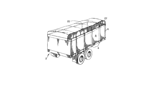
FIGURE 1 is a perspective view of a flatbed trailer on
which a plurality of stakes in accordance with the present
invention, and associated wall panels, have been mounted;
FIGURE 2 is a perspective, enlarged, partial view showing
details of the upper portion of the stake construction of FIGURE l;
FIGURE 3 is a perspective, enlarged, partial view, from
the inside, of the lower portion of the stake construction of
FIGURE 1, illustrating the manner in which that stake fits into a
pocket along the edge of the flatbed trailer;
FIGURE 4 is a partial perspective view of the lower
portion of the stake construction of FIGURE 3;
FIGURE 5 is a top plan view of a conventional prior art


.

_ 4 _ 2061 i 8 6

sta]ce construction; and
FIGURE 6 is a top plan view of the stake construction of
FIGURES 1 and 2.
While the invention will be described in conjunction with
an example embodiment, it will be understood that it is not
intended to limit the invention to such embodiment. on the
contrary, it is intended to cover all alternatives, modifications
and equivalents as may be included within the spirit and scope of
the invention as defined by the appended claims.


DETAILED DE8CRIPTION OF THE INVENTION

In the drawings, similar features have been given similar
reference numerals.
Turning to FIGURE 1 there is illustrated a flatbed
trailer 2 in which are positioned, in pockets ~ along the edge of
trailer 2 a plurality of stakes 6 in accordance with the present
invention. Stakes 6 support, in a manner which will be described
in more detail hereinafter, wall panels 8 in vertical orientation.
As can be seen in FIGURES 2, 3, 4 and 6, stake 6
comprises an elongated main body portion 10 extending the length of
the stake and having a uniform transverse cross-section. A bottom
end portion 12 (FIGURE 3) is formed, as illustrated, so as to be
releasably received in pocket 4. (Depending upon the construction
of pockets 4, and the fit required for stake 6 therein, the
transverse cross-section of bottom end portion 12 may be the same
as or vary from that of the rest of main body portion 10).


20~1186


Extending the length of stake 6, down to bottom end portion 12, are
a pair of spaced flanges 12 and 14, extending outwardly in parallel
fashion on opposite sides of main body 10, to form with it a pair
of oppositely disposed channels 16 to slidably receive, as
illustrated in FIGURE 2, edges of panels 8. Corresponding flanges
14, which form the exterior side of stake 6 when in position on the
trailer as illustrated in FIGURE 1, are reinforced by means of
additional bracing material 18, as illustrated, to buttress those
exterior flanges 14 against forces which may be exerted on them by
corresponding portions of panels 8 when cargo fills the trailer.
The top of stake 6 is preferably provided with an
aperture or pocket 20 for releasably receiving the lower ends of
tarpaulin rods 22
The bottom 12 of stake 6 has the exterior flanges 14
trimmed with notches 24, as illustrated, to fit securely into
pockets 4 and provide a shoulder 26 upon which the upper section of
the stake rests on the upper peripheral portions of pocket 4, to
prevent the stake from passing through the pocket. In the
illustrated embodiment, interior flanges 12 remain untrimmed and
equal the trimmed dimension of flanges 14. (To fit smaller pockets
4, it may be required to trim both exterior flanges 14 and interior
flanges 12 equally).
As can be seen in FIGURE 3, when a panel 8 is in position
in channel 16, it rests on a support ledge 30 located between stake
pockets 4 and providing, therebetween, a flat support surface for
those panels. In this manner, unlike prior art stakes, the stake

6 accordlng to the present invention does not require channels 16


., -


-

6 2061~86

to be fully removed from the bottom section 12 in order for the
stake to fit in the pockets 4, thereby providing increased strength
in 1:his area. As well, stake 6 according to the present invention
allows panels 8 to sit entirely outside the trailer deck 32 (FIGURE
3) - excluding pockets 4.
When comparing the plan views of the stake according to
the present invention (FIGURE 6) with the plan view of a prior art
stake (FIGURE 5) can be seen that the stake construction of the
present invention permits the panels, when in position, to be
positioned, laterally of pockets 4, rather than inwardly thereof,
as was the case with prior art stakes. In that construction,
oppositely disposed panel-receiving channels 16 are provided by
means of a "T" section 19 which extends along the length of a flat
side of the main body section 10 of the stake. Thus it can be seen
that the stake construction of the present invention provides a
greater platform area for loading and carrying of cargo than does
the conventional, prior art construction. As well, it should be
noted that the stake construction according to the present
invention fully incorporates the panel-receiving channels 16 in the
geometric shape of the stake.
Thus it is apparent that there has been provided in
accordance with the invention stakes for flatbed trailers that
fully satisfies the objects, aims and advantages set forth above.
While the invention has been described in conjunction with a
specific embodiment thereof, it is evident that many alternatives,
modifications and variations will be apparent to those skilled in
the art in light of the foregoing description. Accordingly, it is


-' 2061186
-- 7

intended to embrace all such alternatives, modifications and
variations as fall within the spirit and broad scope of the
invention.


,, ~


::: :: : : ' : :


.~ :

,: .
:~
.
. . ~ ~ ;, -
.

Representative Drawing
A single figure which represents the drawing illustrating the invention.
Administrative Status

For a clearer understanding of the status of the application/patent presented on this page, the site Disclaimer , as well as the definitions for Patent , Administrative Status , Maintenance Fee  and Payment History  should be consulted.

Administrative Status

Title Date
Forecasted Issue Date 1998-01-20
(22) Filed 1992-02-13
Examination Requested 1992-02-13
(41) Open to Public Inspection 1993-08-14
(45) Issued 1998-01-20
Expired 2012-02-13

Abandonment History

There is no abandonment history.

Payment History

Fee Type Anniversary Year Due Date Amount Paid Paid Date
Application Fee $0.00 1992-02-13
Maintenance Fee - Application - New Act 2 1994-02-14 $50.00 1993-12-06
Maintenance Fee - Application - New Act 3 1995-02-13 $50.00 1995-01-19
Maintenance Fee - Application - New Act 4 1996-02-13 $50.00 1996-02-06
Maintenance Fee - Application - New Act 5 1997-02-13 $75.00 1997-02-04
Final Fee $150.00 1997-06-10
Maintenance Fee - Patent - New Act 6 1998-02-13 $75.00 1998-02-13
Maintenance Fee - Patent - New Act 7 1999-02-15 $75.00 1999-02-10
Maintenance Fee - Patent - New Act 8 2000-02-14 $75.00 2000-02-10
Maintenance Fee - Patent - New Act 9 2001-02-13 $75.00 2001-02-05
Maintenance Fee - Patent - New Act 10 2002-02-13 $100.00 2002-02-06
Maintenance Fee - Patent - New Act 11 2003-02-13 $100.00 2003-02-13
Maintenance Fee - Patent - New Act 12 2004-02-13 $125.00 2004-01-12
Maintenance Fee - Patent - New Act 13 2005-02-14 $125.00 2005-02-07
Maintenance Fee - Patent - New Act 14 2006-02-13 $325.00 2006-07-06
Maintenance Fee - Patent - New Act 15 2007-02-13 $225.00 2006-11-02
Maintenance Fee - Patent - New Act 16 2008-02-13 $225.00 2007-11-19
Maintenance Fee - Patent - New Act 17 2009-02-13 $225.00 2009-01-29
Registration of a document - section 124 $100.00 2009-12-04
Maintenance Fee - Patent - New Act 18 2010-02-15 $225.00 2010-02-10
Maintenance Fee - Patent - New Act 19 2011-02-14 $225.00 2011-02-07
Owners on Record

Note: Records showing the ownership history in alphabetical order.

Current Owners on Record
PETELKA INVESTMENTS LTD.
Past Owners on Record
PETELKA, BRIAN W.
Past Owners that do not appear in the "Owners on Record" listing will appear in other documentation within the application.
Documents

To view selected files, please enter reCAPTCHA code :


To view images, click a link in the Document Description column. To download the documents, select one or more checkboxes in the first column and then click the "Download Selected in PDF format (Zip Archive)" or the "Download Selected as Single PDF" button.

List of published and non-published patent-specific documents on the CPD .

If you have any difficulty accessing content, you can call the Client Service Centre at 1-866-997-1936 or send them an e-mail at CIPO Client Service Centre.


Document
Description 
Date
(yyyy-mm-dd) 
Number of pages   Size of Image (KB) 
Cover Page 1993-11-13 1 17
Abstract 1993-11-13 1 29
Claims 1993-11-13 2 60
Drawings 1993-11-13 2 77
Description 1993-11-13 7 261
Claims 1997-01-28 2 52
Cover Page 1998-01-23 1 49
Representative Drawing 1998-01-23 1 13
Fees 2000-02-10 1 40
Fees 2003-02-13 1 32
Assignment 2010-02-24 3 100
Fees 2010-02-10 1 34
Fees 2004-01-12 1 31
Fees 2001-02-05 1 32
Fees 2002-02-06 1 32
Fees 1999-02-10 1 43
Fees 1998-02-13 1 43
PCT Correspondence 1997-06-10 1 41
Office Letter 1992-08-04 1 41
Prosecution Correspondence 1993-12-06 1 34
Prosecution Correspondence 1996-08-28 5 145
Prosecution Correspondence 1994-06-07 2 44
Examiner Requisition 1996-05-03 2 80
Examiner Requisition 1994-02-24 1 52
Fees 2005-02-07 1 27
Fees 2006-07-06 1 27
Fees 2006-11-02 1 28
Correspondence 2007-11-06 2 40
Fees 2007-11-19 1 29
Fees 2009-01-29 1 34
Assignment 2009-12-04 3 114
Correspondence 2010-02-16 1 17
Fees 2011-02-07 1 34
Fees 1997-02-04 1 39
Fees 1996-02-06 1 41
Fees 1995-01-19 1 45
Fees 1993-12-06 1 30