Note: Descriptions are shown in the official language in which they were submitted.
2061190
PROCESS AND APPARATUS FOR PRODUCING PUMPABLE
FOODSTUFFS, IN PARTICULAR PROCESSED CHEESE
BACXGROUND OF THE INVENTION
The present invention relates to a process
for producing pumpable foodstuffs, in particular
processed cheese, wherein raw foodstuffs such as raw
cheese is pre-comminuted, mixed with further
ingredients, thermally treated by steam injection,
subsequently cooled and creamed or emulsified and
then fed or passed to a further working or
processing operation. The present invention further
relates to an apparatus for producing pumpable
foodstuffs, such as processed cheese, having a
treatment apparatus for raw foodstuffs, a mixer, a
device or unit for heating and subsequently cooling
the cheese mass and having feed pumps for the cheese
mass.
Pumpable foodstuffs comprise liquid and
viscous foodstuffs, such as for example mild and
processed cheese products, soups, sauces,
mayonnaises and baby foods and like products.
However, for the sake of simplicity and brevity,
exemplary reference will be made in the
specification and claims to cheese, and this
reference is intended to include the various
different foodstuffs and products as listed above.
SUMMARY OF THE INVENTION 2 0 6
An object of the present invention is to
provide a process that satisfies and meets the
needs, requirements and criteria for commercial
production of pumpable foodstuffs without the
shortcomings and disadvantages of prior art
processes in a simple, safe and cost-effective
manner while allowing the production of any given
recipe over prolonged periods of production run time
with low operating costs. The present process for
producing pumpable foodstuffs may be carried out in
batch mode, i.e., discontinuously, or may be
conducted continuously. A further object of the
present invention is to provide an apparatus
suitable for carrying out such a process.
Additional objects and advantages of the
invention will be set forth, in part, in the
description which follows and, in part, will be
obvious from the description, or may be learned by
practice of the invention. The objects and
advantages of the invention may be realized and
attained by means of the elements and combinations
particularly pointed out in the appended claims.
To achieve the objects and in accordance with
the purpose of the present invention, as embodied
and broadly described herein, the process for
producing pumpable foodstuffs comprises the steps of
a) comminuting and mixing a foodstuff to obtain a
uniform, standardized mass of foodstuff, b) heating
the uniform, standardized mass of foodstuff to a
predetermined temperature by introducing steam and
subjecting the mass of foodstuff to a condition of
2~ 61 ~ 9 0
high turbulence by rotating an agitator in said
mass at 1000 to 4000 rpm, the steam being
introduced at a rate such that condensate from the
steam gives off substantially all of its heat
energy; and c) emulsifying the heated mass of
foodstuff. The emulsified, heated mass of
foodstuff may be pumped to a temperature-
maintaining and reaction chamber before further
processlng.
The process may further comprise injecting
steam in a superpressure range, e.g., up to about
8 bar, into the flowable foodstuff in a flashing
unit or zone after emulsifying the heated mass of
foodstuff and thereby further heating the
emulsified heated mass of foodstuff to a
temperature of at least about 150~C. It would also
be preferable to subject the mass of foodstuff to
a condition of high turbulence in the flashing unit
or zone. The mass of foodstuff may be conveyed to
a heat-maintaining section after being subjected to
steam and high turbulence in the flashing unit or
zone.
The process of the present invention may
further comprise cooling the emulsified mass of
foodstuff in an expansion and creaming unit or zone
using a vacuum condenser system. The emulsified
mass of foodstuff may be creamed by slowly rotating
tools in the expansion and creaming zone. The
emulsified mass of foodstuff may be conveyed to a
buffer tank after cooling, and from the buffer tank
to a filling machine.
It is preferred that a level of vacuum for
the vacuum condenser system be set such that an
amount of water equal to the amount of water that
20611~0
was injected into the foodstuff as steam in the
expansion and creaming zone is removed from the
foodstuff.
In another embodiment of the present
invention, there is provided an apparatus for
producing a pumpable foodstuff comprising a) a
treatment unit for comminuting and mixing a
foodstuff, b) a mixing and melting unit for mixing
and melting foodstuff from the treatment unit and
having 1) a mixing chamber within a housing, 2) a
mixing and feeding shaft extending into the mixing
chamber, the mixing and feeding shaft being
operatively connected to a drive unit outside the
mixing chamber, 3) a foodstuff intake provided
adjacent to the mixing chamber housing,
approximately axially in line with the mixing and
feeding shaft, and 4) steam injectors opening into
or upstream of the mixing chamber in a direction
approximately perpendicular to the axis of the
mixing and feeding shaft, c) an emulsifying unit
adjacent the mixing and melting unit for emulsifying
foodstuff from the mixing and melting unit and
having 1) an emulsifying chamber within a housing,
2) a set of homogenizing and emulsifying tools, and
3) a processed foodstuff outlet conduit leading out
from the emulsifying chamber.
The set of homogenizing and emulsifying tools
may include a) a stator arranged fixedly in the
emulsifying chamber housing, and b) a rotor enclosed
concentrically by the stator without contact,
the stator and rotor being arranged axially
downstream of the mixing and feeding shaft and
rotating together with the mixing and feeding shaft.
2061190
The stator has axially directed teeth, forming axial
slits between them. Preferably, the axial slit
between the axially directed teeth of the stator and
rotor is between about 0.05 to 10 mm. The m; X; ng
and feeding shaft and the rotor may be fastened
directly on the drive shaft of the drive unit, and
the housing containing the emulsifying chamber may
be flange-mounted on the drive unit. The drive unit
may be a variable speed drive unit. The apparatus
of the present invention may further comprise a
flashing unit adjoined to the emulsifying unit. A
temperature-maintaining and reaction unit between
the emulsifying unit and the flashing unit may also
be provided.
The present apparatus may further comprise an
expansion and creaming unit having a vacuum-tight
expansion and creaming tank and a vacuum-condensor
system operatively engaged with the vacuum-tight
expansion and creaming tank. Again, a temperature
maintaining unit may be provided between the
flashing unit and the expansion and creaming unit.
The apparatus of the present invention may
further comprise a filling unit adjoining the
expansion and creaming unit. The filling unit may
include a buffer tank and a filling machine. Once
again, a temperature maintaining unit may be
provided between the expansion and creaming unit and
the filling unit. In order to maintain the vacuum
condenser system and the vacuum-tight expansion and
creaming tank clean, cleaning lines may be
operatively connected to the vacuum-tight expansion
and creaming tank.
Such continuously operating processes and ap-
2U61190
paratuses can be operated in a simple and costeffective manner using currently available automated
control technology such as programmable computer
controlled machinery and robotic equipment. Thus,
the need for permanent, specially trained experts
and technicians for the purpose of controlling the
production process as well as the need for full-time
machine operators is alleviated with the added
savings in production costs.
The continuous process according to the
present invention is generally preceded by a
discontinuous treatment process. When producing
processed cheese, the raw material, i.e., raw
cheese, is comminuted in a cheese mincer and
together with all of the additional ingredients,
mixed in a mixing system to yield a homogeneous mix.
This mix, not yet thermally treated, has an average
particle size between 1 to 4 mm. Mixers which can
mix up to 5000 kg per batch are preferred, although
a variety of different types of mixers having
different load capacities can be used. Samples may
be taken after the comminuting step or after the
mixing step and analyzed in order to determine
whether adjustments need to be made to the
ingredient content such as fat and water content to
the extent necessary to meet exact content
prerequisites, which is of great commercial benefit
and facilitates compliance with governmental
standards and provisions relating to cheese.
The homogeneous mix is then placed in a
chamber and subjected to cooking action by applying
heat, preferably in the form of steam, and then
immediately subjected to turbulence action. Within
2061190
a brief moment of time, i.e., few seconds, heat from
the steam is transferred to the cheese mass, and the
cheese mass becomes heated, for example, to 95 C.
The heated cheese mass is then immediately subject
to emulsification or creaming action with
appropriate machinery and tools that impart high
speed rotating action on the cheese mass. A proces-
sed cheese which meets strict requirements regarding
appearance, gloss, spreadability and texture is
thereby obtained.
It is to be understood that both the
foregoing general description and the following
detailed description are exemplary and explanatory
only and are not restrictive of the invention, as
claimed.
The accompanying drawings, which are
incorporated in and constitute a part of this
specification, illustrate one embodiment of the
present invention and together with the description,
serve to explain the principles of the invention.
BRIEF DESCRIPTION OF THE DRAWINGS
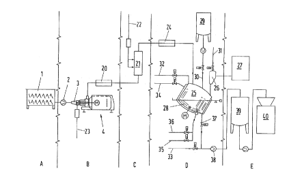
Fig. 1 is a schematic diagram illustrating
the process for producing processed cheese.
Fig. 2 is an enlarged, side, elevational,
part-sectional view of the mixing and melting
apparatus as represented in Fig. l, turned 180 with
respect to the latter representation.
Fig. 3 is an enlarged, side, elevational,
schematic diagram showing an intake 3 as shown in
Fig. 2.
Fig. 4 is a partially cross-sectional, plan
2061190
view of a stator of the mixing and melting unit or
device.
Fig. 5 is an enlarged, detailed
representation in section of the stator in Fig. 4.
Fig. 6 is a sectional diagram taken along
line VI-VI in Fig. 4.
DESCRIPTION OF THE PREFERRED EMBODIMENTS
Reference will now be made in detail to the
present preferred embodiments of the invention,
examples of which are illustrated in the
accompanying drawings. Wherever possible, the same
reference numbers will be used throughout the
drawings to refer to the same or like parts.
Referring now to Fig. 1, it can be seen that
the process of the present invention may be
subdivided into various treatment steps or regions,
namely, a mixing region A, a ~;x;ng and melting
region B, a flashing zone C, an expansion and
creaming zone D, and a filling region E.
Foodstuff such as raw cheese, generally in
large hunks or pieces, is minced in special cheese
mincers to an average particle size of between 1 and
4 mm and then charged using known feeding means into
a mixer 1, which is diagrammatically represented in
Fig. 1 in the mixing region A. This mincing
operation is performed discontinuously or
continuously as required, depending on the amount of
foodstuff to be processed. While various different
types of mixers having different load capacities may
be used, a preferred mixer may be an open, double-
screw mixer which is capable of processing up to
2061190
5000 kg. of foodstuff, such as cheese, per batch
~;~;ng session. In the mixer 1, the minced raw
cheese is intimately and homogeneously mixed with
any additional ingredients at a mixing temperature
of approximately between 15 and 30 C. The cheese
mixture is thereafter analyzed, and the fat and
water content as well as, perhaps, pH are measured
and adjusted as necessary according to set standards
and requirements.
The treated, standardized cheese mass is
pumped out of the mixer 1 by a dairy pump 2 into the
intake 3 of a continuously operating mixing and
melting apparatus 4. It is possible to use a
frequency-controlled motor in place of the dairy
pump drive 2 for automatic control of the feed flow.
Figs. 2 and 3 show the construction of the
mixing and melting apparatus 4. The drive of the
mixing and melting apparatus can be performed by
means of any suitable, commercially available drive
unit or motor (not shown in detail). The drive unit
is operatively connected to a drive shaft 5 which,
in turn, is operatively associated with a mixing and
feeding shaft 6. The mixing and feeding shaft 6 is
fitted with radially directed mixing tools 7 which,
by virtue of an appropriate angle of pitch, impart
to the material to be mixed an axial feeding action
in the direction of the drive unit. The mixing and
feeding shaft 6 rotates within a mixing chamber 8,
and as seen in a direction against the product
feeding direction, the mixing chamber is adjacent a
steam blowing-in zone or steam injection chamber 9
which, in turn, is adjacent an intake chamber 3.
The steam may be introduced through steam injectors
206~ ~90
located on the circumference of the wall of the
steam injection chamber 9. The steam injectors may
be in the form of nozzles, a steam ring, steam non-
return valves 10 or the like.
The motor or drive shaft 5 is generally
rotated at speeds between 1000 and 4000 rpm. As
seen in Fig. 3 and in the product feeding direction,
a rotor 11 is integrally mounted on the motor shaft
5 downstream of the mixing and feeding shaft 6 and
rotates within a stationary stator 12. An
emulsifying unit, comprising the rotor 11 and the
stator 12, is arranged and housed in an emulsifying
chamber 13. The housing of the emulsifying chamber
13 is flange-mounted directly on the drive unit. A
processed cheese outlet tube 14 leads out of the
housing of the emulsifying chamber 13 and guides or
leads the emulsifying unit 11, 12 downstream in the
radial direction.
Referring to Figs. 4 to 6, the stator 12 has
axially directed teeth 16, forming axial slits 15
between them. Cutting profiles 17 designed as tips
are fastened on the teeth 16. Two axial edges are
provided on each cutting profile 17. One axial edge
of the cutting profile 17 is designed and adapted as
a cutting edge 18, whereas the other axial edge,
together with the cutting edge of the following,
adjacent cutting profile 17 forms a cutting gap 19.
The emulsifying unit may, alternatively be designed
according to the form and configuration represented
in EP-B1 0 005 726
Steam is introduced and injected into the
steam blow-in zone (or steam injection chamber) 9
--10--
B
2061190
via steam non-return valves 10. The quality of the
steam is of drinking water quality, i.e., potable,
and is preferably at a temperature of approximately
140 C. In principle, however, the temperature of the
injected steam could also be about 170 C, which
higher temperature steam would require a
correspondingly greater outlay and investment on
apparatus and equipment. The steam injection is
preferably performed immediately before the pumped-
in raw cheese mass is taken up by the mixing tools7, rotating at high speed, and subjected to high
turbulences in order that the water vapor can give
off its energy through condensation to the cheese
mass. The result is that the cheese mass is heated
in a matter of seconds to a desired temperature of
approximately 95 C. In accordance with the
invention, the high turbulent conditions are
necessary in order to quickly effect transfer of
heat energy in the steam to the cheese mass. The
steam pressure may in this case be up to 8.0 bar.
The rate of steam injection into the steam blowing-
in zone or chamber is regulated such that, according
to the cheese mass flowing through, the condensate
preferably gives off approximately 100% of its
energy, so that no free steam is available to escape
from the system.
In the case of a continuously operating
installation, mixing and feeding shaft 6 and rotor-
stator system 11, 12 can be varied according to
hourly output, recipe and expected quality as well
as speed, in order to accomplish different
intensities of turbulences and homogenizing effects.
For example, the rotor-stator system can, depending
2061190
on the desired homogenizing intensity, have
homogenizing gaps of between approximately 0.05 to
10 mm, preferably between approximately 0.1 and 3
mm. By adjusting the distance of the homogenizing
gaps, just as by changing the speed, the shearing
forces can be varied. All these factors and
possibilities for making changes have a significant
influence on the emulsion, the dispersion effect,
and, consequently, also directly on the appearance,
the gloss, the spreadability and the texture of the
cheese mass. With the technology according to the
present invention, all physical, thermal and
chemical factors acting in the melting process can
be matched optimally with one another so that
optimal end product results as desired product
characteristics can be obtained. Continuously
operated heating and emulsifying processes can be
controlled by automatic control units or devices in
such a way that the quality of the end product is
consistently uniform.
According to Fig. 1, the treatment of the
cheese mass is followed downstream by a temperature-
maintaining and reaction section 20, which is
downstream of the processed cheese outlet tube 14
and, depending on the product and the product
temperature, permits the choice of a temperature-
maintaining time of between about 4 to 180 seconds,
for example, not only for spreadable processed
cheese products but also for block and sliced
cheese.
According to Fig. 1, this temperature-
maintaining and reaction section 20 is adjoined by
a flashing unit 21, where the processed cheese mass
-12-
2061190
is heated, for example, from about 95 C to about
140 C, in order to significantly prolong the shelf
life of the cheese. The process is performed in the
superpressure range by injection of steam via a
steam line 22 similar to the steam line 23 connected
to the steam non-return valves 10 of the mixing and
melting apparatus 4.
Referring to Fig. 1, the flashing unit or
zone C is adjoined by the expansion and creaming
unit or zone D. After running through a further
heat-retaining unit or section 24, the cheese mass,
now already referred to as processed cheese, passes
into a vacuum-tight expansion and creaming tank 25.
A vacuum system 26 as well as a condenser 27 is
attached to the expansion and creaming tank 25 for
the precipitation of water vapor vacuumed out of the
tank 25. Combined, the vacuum system 26 and the
condenser 27 form a vacuum condenser system. In the
expansion and creaming tank 25, the temperature of
the processed cheese, which may be between about 95
and about 140C, is lowered by a defined vacuum level
within a matter of seconds to a desired product or
creaming temperature of about 80 C. Vacuum level and
product temperature are kept constant by automatic
control. Rotatable mixing and creaming tools 28,
which can be driven at speeds of between about 5 and
about 50 rpm, are provided in the tank 25. The
creaming of the processed cheese is improved by the
use of these tools. Moreover, additional
ingredients can be added in this way so as to be
mixed into the processed cheese mass. For this
purpose, an ingredients tank 29 as well as a supply
line 30, which is fitted with a pump and shut-off
-13-
2061190
valve and which opens out into a suction intake
opening of the tank 25, are indicated in Fig. 1.
The expansion and creaming tank 25 is mounted
on weighing cells, by means of which the amounts of
5 precooked cheese and the filling level of the tanks
can be constantly monitored and exactly determined
during production. For example, the filling level
which corresponds to a certain weight can be
visually indicated on a display on the switch
cabinet.
In order to be able to carry out a cleaning
of the expansion and creaming tank 25 as well as of
the vacuum tank of the vacuum system 26 continuously
during the process, three cleaning lines 31, 32 and
15 33, each fitted with shut-off valves, are connected
to the tank 25. The expansion and creaming tank 25
is consequently able to meet stringent hygienic and
aseptic requirements with regard to its housing and
its internal fittings. This means, inter alia, that
20 dead spaces, in which residues can be deposited, are
avoided. No slotted screws which could come into
contact with the product may be used. The gaps of
all shaft glands are cleaned directly.
According to Fig. 1, water lines 34, 35 and
25 a steam line 36 are also connected to the expansion
and creaming tank 25. Moreover, the tank 25 has a
bottom seat valve 37 for continuously pumping off
the ready, produced and subsequently creamed
processed cheese. The feeding of the ready,
3 0 produced and subsequently creamed processed cheese
is performed continuously, for example, by means of
a gear pump 38, into a buffer tank 39 and from there
into a filling machine 40.
2061190
It will be apparent to those skilled in the
art that various modifications and variations can be
made in the process of the present invention and in
the construction of this apparatus without departing
from the scope or spirit of the invention.
Other embodiments of the invention will be
apparent to those skilled in the art from
consideration of the specification and practice of
the invention disclosed herein. It is intended that
the specification and examples be considered as
exemplary only, with true scope and spirit of the
invention being indicated by the following claims.