Note: Descriptions are shown in the official language in which they were submitted.
2 t~ 2 3
HIG~I EFFICIENCY ABSORPTION CYCLE OF THE GAX TYPE
BACKGROUND_OF THE INVENTION
This invention relatss generally to refrigeration
and heat pump equipment and particularly to an absorption
refrigeration cycle of the generator absorberheat-
exchange type. The invention is especially adapted for use
in gas-fired, absorption heat pump~. The present invention
was developed with support from the Federal Government and
as such, the Government has ce~tain rights in the invention.
The potential energy saving benefits of heat
activated heat pumps for medium temperature heating and
cooling functions, including space heating and cooling~ have
been known. For example, the air conditiontng of
residential and commercial structures is a large user of
electrical energy. The natural-gas-fired heat pump has the
ability to slow the requirement for the addition of
electrical generating capacity by supplanting 3uch
electrically-operated systems. In addition, an alternative
is provided to khe use of CFC'~ as a working fluid, which
CFC's are considered to be harmful to the environment.
Furthermore, in its heating mode, the absorption heat pump
has the potential of reducing the gas usage to hal~ that oP
a state-of-the-art gas furnace and to match the primary
energy-efficiency of a good electric air conditioner in the
cooling mode.
In order to reali7e its potential, for general
application across the United States, it has been determined
that an air-to-air residential and small commercial
2~61~3
1 absorption heat pump system should operate at a coefficient
of performance (COP) at ARI rating conditions approaching
1.8 in the heating mode and 0.9 in the cooling mode, based
on gas-firing at flue efficiencies of 90 percent or greater
and using the high hea~ing value of the gas. It is
additionally deemed desirable for such system to be capable
of meeting ~he total heat requirements of a building without
supplemental heat, under a full range of operating
conditions, including outside ambient air temperatures of as
low as -10 F.
While water-cooled absorption cycles used in large
scale industrial and commercial applications have been
dsvised that meet or Qxceed these cooling COP's, such
water-cooled cycles and their fluids do not meet those COP~s
in air-to-air applications, nor are they suited for the low
outdoor temperatures. In order to be commercially
success~ul in the residential and small commercial
applications, a natural-gas-fired heat pump must be an
air-to-air system and free from undue complexities and have
a predicted lifetime of 20 years or greater. Furthermore,
all applicable codes and standards must be met.
The present inventor has evaluated known
absorption cycles and has determined that one cycle having
the potential for meeting the above requirements is the
generator-absorber heat--exchange (GAX) cycle. The GAX cycle
is a further refinement on the absorber heat-exchange (AHE)
cycle, which uses absorber heat to warm the strong solution
of absorbent and refrigerant and utilizes the sensible heat
of the weak solution as heat input to the generator. Such
AHE cycles have been used in ammonia/water air conditioner
production units for at least twenty-five years and have
2~1323
1 been found to have gas-fired COP's of up to 0.5 at ARI
ratin~ conditions. This cycle has also been used in
experimental gas-heat pumps to produce heating coP~s ~f
1.25. In the AHE cycle, the recuperation of absorber heat
is limited by the sensible heat of the strong solution.
Similarly, recuperation heating of the generator is limited
to the sensible heat in the weak solution leaving the
generator.
The GAX cycle adds to the recuperation gains o~
the AHE cycle by increasing the absorber and generator
temperature ranges so that the two temperature ranges
overlap. Under these conditions, absorption heat is
transferred to the generator at the overlap temperatures
using various means such as a separate heat transfer loop.
This heat transfer can occur whenever the weak solution
concentration is decreased to the point that the temperature
of the hot end of the absorber is above that of the cool end
of the generator. All of the heat of absorption in the
overlap range can be utilized by the generator, except for
heat-transfer temperature differences. By increasing the
extent of overlap between the temperature ranges of the
absorber and generator, improved system COP's may be
obtained. Therefore, the need exists for ways to increase
the extent of overlap between the temperature range of the
generator and the temperature range of the absorber, and to
increase the heat of absorption in the absorber overlap
range.
Hybrid systems havé been proposed in which
absorption systems are augmented with mechanical
compressors. However, such systems merely reflect
combinations of alternate forms of energy inputs to the
2 ~ 2 ~
1 system, without greatly altering the overall COP o~ the
system. One such system is proposed in U.S. Patent
5,024,063 to Erickson which discloses the use of a
mechanical compressor on the vapor outlet of an absorption
system generator to elevate the temperature at which thermal
energy may be trans~erred from the condenser to the
surroundings.
I~ the known prior system, a heat pump 10 operated
on the generator-absorber heat-exchange (GAX) principle
provides low-pressure refrigerant vapor leaving evaporator
12 through conduit 14 to enter absorber 16 where it is
absorbed in a weak solution of absorbent and refrigerant,
such as ammonia and water (FigO 1). This process taXes
place at temperatures above that of the surroundings,
generating heat. A lower temperature portion of that heat
is transferred to a coolant (for example a water-antifreeze
mixture) circulating during this process in a heat exchanger
18. The strong absorbent/refrigerant solution is then
transferred by a solution pump 20 to the generator 22, where
a higher pressure is maintained. Refrigerant vapor is
driven from the solution in generator 22 as a result of heat
transfer from a high temperature source 24, which is
assisted by the additions of heat transfer fins 45. The
refrigerant vapor is expelled from generator 22 through
conduit 26 to a condenser 28 where it is condensed and fed
through an expansion valve 30 and expanded in evaporator 12.
The weak solution is returned through conduit 32 to absorber
16. At very low outdoor temperatures heat may be
transferred in a liquid heat exchanger (not shown) between
the strong solution conduit 36 and the weak solution conduit
38. In accordance with the AHE cycle principle, absorber
2~1323
1 heat is also used to warm ~he strong solution at 40, and the
sensible heat of the weak solution is provided as a heat
input to a section of the generator at lower temperature 42.
In addition, as disclosed in detail in U.S. Patent 4,127,010
issued to the present inventor, entitled HEAT ACTIVATED HEAT
PUMP METHOD AND APPARATUS, additional efficiencies may be
gained by Qxchanging heat between the strong solution
conduit 36 and the reErigerant/absorbant vapor mixture at 44
and by providing a pre-cooler 46 to transfer condensate heat
to the refrigerant vapor and excess liquid.
In the case of the generator-absorber heat
transfer function, illustrated ln Fig. 1, the high
temperature heat transfer is performed by a G~X heat
trans~er means 48, including, for example, a pair of heat
exchange coil~ 50 and 52 and a pump 54 to circulate
heat-transfer fluid such as pressurized water. Because the
vertical temperature gradients o~ absorber 16 and generator
22 are rever&ed, it iq necessary to cross-connect the lines
between coils 50 and 52, as illustrated in Fig. 1. The
transfer of GAX heat from the absorber to the genexator can
be accomplished in various ways. The transfer should be
provided over the full overlap temperature range. The
principle of the GAX cycle is illustrated in the
pressure-temperature-composition diagram o~ Fig. 2 in which
line C-G represents the low temperature portion of the
absorber, line G-F the high temperature portion of the
absorber, line D-I the low temperature portion of the
generator and line I-E the high temperature portion of the
generator. Points A and B represent the condenser and
evaporator, respectively. The line from C to D represents
-5-
2~3~,3
1 the strong solution pathway and line from E to F the weak
solution pathway. The temperature overlap between the G to
F region of the absorber and the D to I region of the
generator provides the generator-absorber heat-exchange as
illustrated by the arrows, indicating hea-t transfer.
SUMMARY OF THE INVENTION
The purpose of the present invention is to provide
a new high-e~ficiency, enhanced, GAX cycle (EnGAX) which
achieves a significant improvement in C0~ with respect to
the known GAX cycle. This is accomplished by incrPasing the
extent of overlap of operating kemperature ranges in an
absorber and generator of a GAX absorption system and by
increasing the absorption in the overlap area of the
absorber. The invention may be embodied in an absorption
heat pump including a generator, a condenser, an avaporator,
an absorber, a strong solution pathway from a low
temperature portion o~ the absorber to the generator, and a
weak solution pathway from the generator to a
high-temperature portion of the absorber. A refrigerant
pathway is provided from the generator to the condenser,
from the condenser to the evaporator and from the evaporator
to the absorber. A GAX heat transfer pathway is provided
between regions of the absorber and generator having
overlapping temperatures.
According to one aspeck of the invention, the
temperature range overlap may be increased by elevating the
absorber operating pressure. This may be accomplished by
locating a vapor compressor in the vapor stream between the
evaporator and the absorber, to increase the operating
pressure of the absorber. According to another aspect of
the invention, means are provided for increasing the flow o~
1 absorbent/refrigerant solution in the temperature overlap
region of the absorber and in a portion of the generator in
order to increase the absorber heat output in the overlap
range. This enhanced cycla is capable of enlarging the
overlap range and of providin~ all of the heat that the
generator can utilize in the overlap range and, therefore,
provides an improvement in performance over the basic GAX
cycle.
According to yet another aspect of the invention,
a GAX cycle is provided that operates to a peak generator
temperature of approximately 500 Fahrenheit. This may be
accomplished by providing a ternary working fluid that
includes ammonia, water, and a dissolved salt. Not only
does this aspect of the inventlon produce an increase in
cycle COP o~ a GAX cycle by increasing the overlap range, it
produces an unexpectedly large enhancement due to the
solution concentrations in the overlap range when combined
with other aspects of the invention.
Although the invention is illustrated embodied in
a gas-fired residential heat pump, its principles apply to
use with other sources of heat and to other refrigeration
and chemical processes. These and other objects, advantages
and features of this invention will become apparent upon
review of the following specification in conjunction with
the drawings.
BRI~F DESCRIPTION_O~F THF DRAWINGS
Fig. 1 is a flow diagram illustrating a
conventional generator-absorber heat-exchange (GAX) cycle;
Fig. 2 is a pressure-temperature-composition
diagram (P-T-X) o~ the cycle in Fig. 1
-7-
_
2 3
1 Fig. 3 is a ~low diagram illustrating an enhanced
GAX cycle according to one aspect o~ the invention;
Fig. 4 is a pressure-temperature-composition
diagram (P-T-X) o~ the cycle in Fig. 3;
Fig. 5 is a pressure-temperature-composition
diagram (P-T-X) of a high-efficiency GAX cycle, using a
ternary working fluid;
Fig. 6 is a flow diagram illustrating an enhanced
generator-absorber heat-exchange ~GAX) cycle according to
another aspect of tha present invention;
Fig. 7 is a pressure-temperature-composition
diagram (P-T-X) of the cycle in Fig. 6;
Fig. 8 is a flow diagram illustrating a hybrid
enhanced GAX cycle using both aspects of the invention;
Fig. 9 is a pressure-temperature-composition
diagram (P-T-X) of the cycle in ~ig. 8;
Fig. 10 is a pressure-temperature-composition
diagram (P-T-X) of the cycle of Fig. 8 showing the heating
of the recirculating str~am by the overlap absorption heat;
Fig. 11 is a flow diagram illustrating a varlation
of the enhanced GAX cycle according to another aspect of the
invention; and
Fig. 12 is a pressure-temperature-composition
diagram (P-T-X) of the cycle of Fig. 11.
DESCRIPTION OF THE PREFERRED EMBO~IMENT
-
As used herein, the terms weak absorption solution
and strong absorption solution refer to the concentration of
the refrigerant in the solution. Thus a weak absorption
solution has less absorbed refrigerant, such as ammonia, and
more absorbent, such as water, than a strong absorption
solution. Also, the term absorption heat pump, as used
2~6~323
1 herein, is intended to include any apparatus that transforms
heat between low, medium and high temperature states and is
intended to include not only the commonly understood meaning
of the term, but also is intended to include heat
transformers as well as more traditional uses such as
refrigeration and related processes.
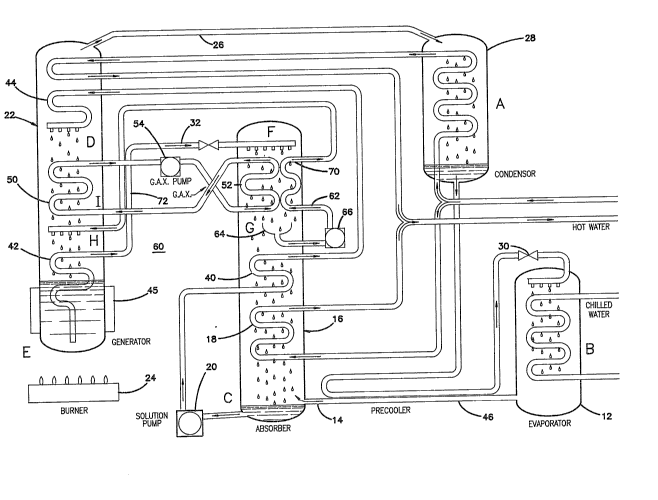
Referring now specifically to the drawings, and
the illustrative embodiments depicted therein, a heat pump
60, incorporating a high-efficiency enhanced &AX (ENGAX)
cycle includes the components of the conventional GAX cycle
heat pump 10, illustrated in Fig. 1, and further includes
augmenting means for increasing the flow of absorbent in the
overlap temperature region o~ the absorber, (line G-F in
Fig. 2) and in the high temperature region of the generator,
(line I-E in Fig. 2). This is accomplished by adding flow
increasing means, generally illustrated at 62, for
transferring additional ~olution from an intermediate to
high temperature portion of absorber 16 to a portion of
generator 22 (Fig. 3). In the illustrated embodiment, flow
increasing means 62 is a solution pathway from an
intermediate temperature portion G of absorber 16 to a high
temperature portion H of generator 22, although the pathway
may initiate at the bottom of the high temperature portion
of the absorber and terminate at a different portion of the
generator. This solution exchange pathway includes a
collector 64 for collecting intermediate-temperature
solution at point G in absorber 16, a second solution pump
66 and a conduit 62 from pump 66 to region H in generator
22. Conduit 62 includes a portion 70 that extends into high
temperature region F of absorber 16, in order to heat the
solution transferred by flow increasing means 62, and a
_g_
~132~
1 second portion 72 in heat trans~er association with weak
solution conduit 32, in order to further incrPase the
temperature of the fluid to point H of the generator, when
necessary.
A comparison of the pressure-temperature
composition diagram of the conventional G~X cycle in Figs. 1
and 2 and that of augmented GAX cycle, illustrated in Figs.
3 and 4 reveals that the heat transferred by the absorber in
the conventional GAX across its overlap range, illustrated
as the line D-I in Fig. 2 is less than the heat that the
generator could utilize over the full overlap temperature
range shown in Fig. 4. It has been discoYered that the main
reason for this inequality is that greater quantities of
absorption solution flow at the lower temperature portions
of the generator and absorber than at the higher temperature
portions thereof. This ineguality of flow results in higher
heat quantities per degree of temperature in the cooler
portions of the absorber and generator than in the hotter of
the two components.
In the enhanced GAX cycle, the solution
recirculation pathway, illustrated in Fig. 4 as the line
from points G ~o H, H to E, E to F and F to G, increases the
flow in the high temperature regions of the absorber (line
F-G) and of the generator (line H-E) and in the weak liquid
pathway (E~F). This increased ~low increases the absorption
and the absorber heat output in the overlap temperature
range so that all of the heat that the generator can utilize
over range D-I in Fig. 4 i5 being provided. The transferred
solution is heated from the temperature at point G to the
temperature at point H by heat transfer from the higher
temperature region 70 of absorber 16 (line G-F in Fig. 4)
--10--
2~1323
1 and heat kransfer from tha weak solution pathway at 72 (line
E-F in Fig. 4) as indicated in Fig. 3.
The flow in the circuit GHEFG must be sufficient
to provide the increased heat input to the generator overlap
region D-I and to also heat the fluid in circuit 62 (line G
to H in Fig. 4) by both absorption heat from the absorber
overlap region F-G and by sensible heat transfer at 72 (See
Fig. 3 and line E-F, Fig. 4) from the weak liquid circuit.
This increase in GAX heat to the generator increases the COP
and can be used to reduce the gas heat input, or to increase
the refrigerating capacity at the same input, or a
combination of the two.
A comparison of the heat balances of the
conventional 5AX cycle with the enhanced, or augmented, GAX
cycle, at the sams operating conditions, as shown in tables
1 and 2, indicates an increase in cycle COP in the cooling
mode of frsm 1.027 to 1.191, or approximately 16%. This
increase in cooling mode performance is especially
significant. It should be noted that the estimated 16%
increase in cooling COP is expected to approach 20% as cycle
operation is further refined. Complete heat and mass
balance calculations for the enhanced GAX cycle (EnGAX) are
set forth in Appendix A, which forms a part of this
application.
2~323
TABLE 1
OPERATING CONDITIONS
All Cycles
PRESSURE TEMP
PSIA o~
Condenser 272.6 117.0
Evaporator68.67 37.0
Absorber 68.67 105.0 - 289,4
Generator 272.6 199.7 - 398.8
_______________________________________________________.___
TABLE 2
HEAT OUTPUTS AND INPUTS
Per Pound of Refrigerant
GAXENHANCED GAX
CYCLE CYCLE
(FIGS. 1 and 2~ (FIGS. 3 and 4)
Rectifier Output 78.44 Btu 78.77 Btu
Condenser Output504.92 Btu 504.92 Btu
Evaporator Input-503.02 Btu -503.02 Btu
Absorber Net Output 409.05 Btu 341.78 Btu
Generator Input -489.73 Btu -422.45 Btu
GAX Heat Transferred 295.96 355.70
Cooling COP 1.027 1.191
Heating COP 2.027 2.191
-12-
2~6~23
l The enhanced, or augmented~ GAX cycle in ~ig. 3
has been illustrated with collector 64 being positioned at
the lower temperature portion of the region of kemperature
overlap with the generator. However, according to the
principles of the invention, it would be possible to
position collector 64 at a higher temperature portion of the
absorber. When solution is collected from the higher
temperature portion of the temperature overlap region, the
narrower temperature range from which solution is collected
incraases the amount of solution which must be circulated
through the enhancing circuit, but the heat i5 at a higher
temperature and i5 therefore more readily transferr~d to the
generator. Thus, depending upon the parameters of the
system, there are optimum temperature ranges over which the
enhancement liquid can be circulatedO
A method of increasing the overlap temperature
range is to use working fluids with a greater temperature
difference between the boiling points of the refrigerant and
-the absorbent~ An example is shown in Fig. 5 in which the
refriyPrant is ammonia and the absorbent is a solution of
60% lithium bromide and 40% water. As can be seen in Fig.
5, the vapor pressure line of the lithium bromide - water
absorbent is at a significantly higher temperature than that
of water alone. As a result khe temperature ranges of the
absorber and generator can be made longer than with
ammonia/water and the absorber overlap range GF can also be
longer.
An additional improvement to the GAX cycle may be
obtained by the use of texnary fluids composed of ammonia,
water and a dissolved salt. A suitable salt extends the
temperature range of the fluid beyond that of ammonia and
2~61323
1 water to 500F, or more, as illustrated in Fig. 5. The
increase in temperature range of the cycle increases the
overlap temperature range between the absorber and
generator. One such ternary fluid is ammonia, water and
lithium bromide, whose vapor pressure properties were
determined by R. Radermacher in a published PhD thesis
entitled, "Working Substance Combinations for Absorption
Heat Pumps."
It has been discovered that the increased overlap
temperature range provided by the use of a ternary working
solution has less than expected benefits in a conventional
GRX cycle. This is believed to be a result of a
redistribution of the ammonia/water concentration gradients
toward a low temperature portion of tha P-T-X diagram.
However, the increased flows of the enhanced GAX (EnGAX) can
be used to overcome the effects of the concentration
gradients for effective performance. Accordingly, the 16~
increase in performance over the conventional GAX cycle may
be increased to 40% or more by the use of a ternary working
fluid and a higher peak generator temperature, in the range
of 500~F with an enhanced GAX cycle. The enhanced GAX cycle
therefore, provides additional unexpected results with
respect to the conventional GAX cvcle when combined with a
ternary working fluid.
The ternary fluid combination of water/ammonia/
lithium bromide, has a disadvantage of being very corrosive
at operating temperatures, even when used with stainless
steels. Other ammonia/water/salt combinations and other
fluids with wide temperature overlap potential are being
investigated. Salts that are believed to have potential
include llthium nitrate and calcium nitrate.
~61323
1 It has been determined that a significant
improvement in system COP's may be obtained in GAX or
enhanced GAX systems described herein by increasing the
operating pressure within absorber 16. By increasing the
absorber pressure, the extent of overlap between the
operating temperatures of absorber 16 and generator 22 is
increased. Thus, a greater proportion of the total
generator hea' requirement can be supplied by absorption
heat, thereby increasing system COP's. Fig. 6 illustrates a
GAX cycle 110 which is the basic GAX~ cycle 10 of Fig. 1
modified by the addition of vapor compressor 80 in conduit
14 between absorber 16 and evaporator 12. A cycle diagram
of the GAX cycle 110 in Fig. 6 is shown in Fig. 7. In Fig.
7 the solid line~ represent the increased-pressure absorber
cycle and the dotted lines the basic GAX cycle of Fig. 2.
Fig. 7 illustrates the effects of increasing the
operating pressure of absorber 16. In the basic GAX,
without increasing the operating pressure of absorber 16 by
use of compressor ~0, the overlap between the temperature
ranges of the absoxber and the generator is represented by
the dotted lines G-F and D-I. After increasing the
operating pressure of absorber 16 by approximately 20 psia,
the operating line for the absorber is modified from C-G-F
to Cl-GI-F'. As a result, the line of constant composition
C-D is relocated to C'-DI. Thus, the point of intersection
between lines G-D and ~-E is changed from D to D'. This
results in the low temperature end of the overlap between
operating temperature ranges of absorber 16 and generator 22
being extended.
In terms of the physical process, the strong
solution increases in concentration, reducing the
-15-
2~323
1 temperature at the solution feed point to generator 22, Fig.
6 (point D' in Fig. 7) as well as the temperature of the
heat transfer liquid exiting the generator to GAX pump 54.
Besides broadening the GAX overlap region, this enrichment
of the strong solution also reduces the rectifier losses
occurring along line D-A of Fig. 7. ~n increase in
operating pressure of absorber 16 also results in a shift of
the point of intersection between lines F-I and A-E, from I
to I'. Thus, the high temperature end of the overlap
between operating temperature ranges of absorber 16 and
generator 22 is also extended. In terms of the physical
process, the concentration of the weak solution is not
changed, but the heat transfer fluid flowing from the
absorber to the generator in line 48 of Fig. 6 is increased
in temperature, thus perhaps requiring relocating the entry
of line 48 into the generator at a lower (and higher
temperature) spot. The result is that provision of means
for increasing pressure in the absorber from C to C' results
in an increase in the overlap temperature range of the
absorber and generator at both the high end and low end of
the overlap range. This increase appears to exceed, to a
significant degree, the mechanical energy required to ra.ise
the absorber pressure.
The amount of pressure increase is to be limited
in view of the additional power reguired for compressing the
vapor, so that the savings from reduced heat requirements
for generator 22 (from burner 24) will be greater than the
extra costs incurred in operating compressor 80. More
specifically, the extent of pressure increase in absorber 16
should be adjusted to maximize the difference between the
-16-
2. ~
1 reduction in energy requirements of generator 22 and the
power requirement of compressor 80.
Alternatively, the enhanced GAX cycle may be
modified according to the present invention, as shown in
5 Fig. 8, in which vapor compressor 80 is likewise located in
conduit 14 between absorber 16 and evaporator 12. Because
conduit 14 discharges to absorber 16, the insertion of
compressor 80 serially in conduit 14 increases the operating
pressure within absorber 16 to a level higher than that in
Figs. 1 and 3. Figs. 8 and 9 illustrate GAX cycle 160, the
combination of the pressurized absorber aspect of this
invention with the increased flow of absorbent through the
overlap portion of the absorber and the absorbent. Tables 3
and 4 indicate the per~ormance gains possible by this
combination. The cycle diagram in Fig. 10 shows that the
heat output from the absorber overlap area is to be
sufficient to supply the needs of the generator and to heat
the recirculated liquid in circuit 62 of Fig. 4.
2~61~23
TABLE 3
HEAT OUTPUTS AND INPUTS
Per Pound of Refrigerant
GAX COMPRESSION
CYCI.E GAX CYCI.E
( FIGS . 1 AND 2 )( FIGS . 6 AND 7 )
Rectifier Output 78 . 44 Btu 45 . 93 Btu
Condenser Output504.92 Btu 504.92 Btu
E~raporator Input-503 . 02 Btu-503 . 02 Btu
Absorber Net Output 409. 05 Btu 372 . 39 Btu
Generator Input-489. 73 Btu -420.22 Btu
GAX Heat Trans~erred 295.96 407.74
Cooling COP 1.027 1.197
Heating COP 2,027 2.197
TABI.E 4
GAX ENHANCED +
CYCLE COMPRESSION GAX
CYCLE
(FIGS. 1 AND 2) (~IGS. 8, 9 AND 10)
Rectifier Output 78.44 Btu 66.19 Btu
Condenser Output 504 . 92 Btu 504 . 92 Btu
Evaporator Input-503 . 02 Btu-503 . 02 Btu
Absorber Net Output 409 . 05 Btu 297 . 73 Btu
Generator Input-489 . 73 Btu-365 . 82 Btu
GAX Heat Transferred 295 . 96 519 . 26
Cooling COP1.027 1.375
Heating COP2.027 2.375
--18--
2~61323
1 In another embodiment of this techni~ue of
improving the system COP in GAX cycles, ik has been found
that increases in absorber operating pressures may be
limited to specific portions of absorber 16. An example is
to compress only the vapor flowing to the absorber GAX
section. Fig. 11 illustrates GAX cycle 210, increasing the
operating pressure in only the temperature overlap (GAX)
portion of absorber 16. In this application vapor
compressor 80 has been moved from the vapor inlet 81 of
absorber 16 to the vapor inlet 82 of the GAX section of
absorber 16. The cooler portion of absorber 16 remains at
evaporator pressure, with only the GAX, overlap, portion
being at a higher pressure. The absorbent liquid flowing
from the higher pressure GAX section to the lower pressure
AHE section is throttled by a suitable restriction 85, to
allow only liquid to ~low from one absorber portion to
anotherO Restriction 85 may be in the form of a float
valve, or other means known to those skilled in tha art.
In the cycle diayram of Fig. 12 the operation for
this concept is shown in solid lines, while that of the
normal GAX is in dotted. Before increasing absorber
pressure 16, the overlap temperature range between the
temperature ranges of absorber 16 and generator 22 is
represented by lines D-I and G-F. After increasing the
operating pressure in only a portion of absorber 16, the
operating line for that particular portion is modified Erom
G-F to G'-F'. This results in the higher end of the
generator overlap being extPnded from D-I to D-I'. Thus,
reduced operating expenses are realized as only a portion of
the refrigerant vapor entering absorber 16 needs to be
increased in pressure, rather than all of the refrigerant
--19--
2~1323
1 entering the absorber. ln the illustrated embodiment it has
been estimated that generally less than 25% of the total
refrigerant to be absorbed need be compressed.
The absorber vapor can be compressed to the higher
pressure at any point between B and F, with varying
advantages in the pumping power re~uired, in equipment cost
and in GAX enhancement. The best temperature at which to
pump the gas is also likely to depend on the relative costs
of natural gas and electricityO The invention is therefore
intended to be useab~e for compression of the vapor at any
temperature, from point B to point F, that is best suited to
the application.
While the enhanced GAX cycle has been illustrated
in a residential or light commercial heat pump, its benefits
are not limited to such applications. The enhanced
performance provided by the EnGAX cycle set forth herein,
may be applied to industrial absorption systems for
applications to processes requiring medium temperature
heating and cooling such as brewing, food processing,
pasturizing and paper making, to mention but a few examples.
Furthermore, the principles of the invention are not limited
to absorption heat pump cycles that efficiently convert heat
from a combination o~ low and high temperatures heat sources
to heat at a medium temperature. The invention is e~ually
applicable to heat trans~ormers which convert heat from a
medium-high temperature, such as heated waste water
discharyed from a processing plant, to a useful high
temperature output plus a low temperature output.
Changes and modifications in the specifically
described embodiments can be carried out without departing
from the principles of the invention. Accordingly, while
-20-
2~13~3
l the means for increasing the flow of solution from the
temperature overlap region of the absorber to the generator
is provided in the illustrative embodiments by a solution
pump and a conduit in heat transfer association with higher
temperature portions of the system, other techniques may be
utilized to transfer the fluid while raising its
temperature. For example, pressurized transfer vessels
incorporating appropriate check valves and control valves,
and other fluid propelling techniques, as are known to those
skilled in the art, may be utilized. Other changes and
modifications will suggest themselves to those skilled in
the art. The protection afforded the invention is intended
to be limited only by the scope of the appended claims, as
interpreted according to the principles of patent law,
including the Doctrine of Equivalents.
-21-
~ ~ 20~23
Heat and Mass Balance Calculation EnGAX Cycl~
DAT~ P T X Y Hx Hy M
COND W 272.60 117 ,~5 .~99947 ~6.426 558.03777
EVAP W 68.667 37 .995 ~999995 3.9331 546.33132
G~N PE~K 272.60 398,8 .0~ .109387 370.64 1151.5539 1.5755
ABS 0UT 68.6~7 105 .~7465 .~93235 ~26.89 589.76183 1.~121
FEED W 272.60 199.7 .4~7465 .974549 78.8~6 62~.35701 1.9121
COND IN 272.60151.7 .6~?030 .995 43.677 586.90823
V TO RCT 27~.60 207 .4~4553 .968844 87.180 636.79318 1.0521
L FR RCT 272.60 ~03 .4~6~41 .972067 82.582 6~2.6~173 .05211
COND OUT 227.72 105 i.99S .999962 81.984 557.58175
PCVI, OUT 68.667 98.17 .5~7~ .995 -34.05 585~00282
AE~S W~ I ~8.667 289.4 1 .0Z .172~67 254.66 ~0~3.5071 1.5755
ABS ILGX 68.S67 210 .1~8611 .817280 129.24 734076fi69 1.2740
ARS IVGX 68.667 200 .2d2760 .855527 112.63 710.45895 .3~184
EGL ABS 68.~67 210 .1718611 .817280 129.24 734.766~9 .fi6 32
EG~ T HG 186.29 283 .17861~ .74525B 20~7,94 797.15268 .66332
~EN I~ W 2?2.60 280 .2~9710 .843155 188.55 740.~614 1.4900
GEN IV W 272.60 290 .2~5659 .811610 204.06 761.6~831 .57~84
~EA~ AND MASS BALANC~
RCTIFI~R P T ~,Y Hx,Hy Lbs Btu
Vap In 2~2.6020~ .9~8844 636.793 1.0521 669.g~
RfL OUT 272.60~03 .466941 82.5820 ,05211 4.3D
Rî~J Out 272.60 151.7 .995 586.908 1 ~86.91
~EC~IF~ER HEAT ou'r 78.77
CON~ENS~R
RrV In 272.60151.7 ,9~5 586.908 1 $86.91
Rf~ OUt 227.72 105 .995 81.9839 1 81.98
CON~ENSER }IEAT OUT 504.92
EVAPORATOR-PRECOOLER
RfL In 227.72 105 .995 81.~839 1 81.~
RfV Out 68.56? ~8.1~ .995 585.003 1 585.00
l~lq OUt ~8.6~7 98.1~ .502676 -3~.045 0 .00
EVAPORATOR HEAT IN -503.02
MAX PRECOOLE~ HEAT -283.46
ABSORE~R
W~ In 68.667 289.4 .02 254.G62 1~S755401.21
Vap In 1 58$,00
Llq ~n 0 .oo
RL Out 27~.60 199.7 .477465 78.8659 1.~121 150.80
EG~ OUT 18fi.~9283 .1~8611 207.940 .66332 137.~3
I{EA~ OF ABSORPTION697.48
LOW TEMP A~SORBER
IL IN 68.667210 .~78~11 129.244 1.2740 164~65
Vap In 58$.00
~IQ IN
R~ OUT 272.60 199.7 .4~7465 78.8659 1.9121 150.80
IV OUT 68.667 200 .855527 710.459 .36184 257.U8
HEA~ OVT 341.78
HIGH TEMP ABSORBER
IV IN 68.667 200 .B5~527 710.459 .36184 257.07521
WL IN 68.667 289.4 .02 254.662 1.575~ 401.2096~
IL OUT 68.667 210 .178611 129.Z44 1.2740 164.65482
EG~ OUT 186.29 283 .1~8611 207.~40 .66332 137.93058
~,AX HEAT 355.6~949
App~ndix A
Page 22
~ ~ 2~6132~
G EN ERi~TOR
RL IN 272.60199.7 .4~7465 78.8659 1.~1~1 150.80264
EGL IN 186.29 283 .178611 207.940 . 66332 137 . g3058
Y TO RCT ~72.60 207 .968844 63fi.7~3 1.0521 6G9.97840
L FR RCT 272.60 203 .466941 82.5820 .05211 4.3035998
WL OIIT 68.667289.4 .02 254.662 1.5755 ~101.20969
-~77~.1513
LO TE~SP G~N~RATOR
RL IN 272.60199.7 .477465 '78.865~3 1.9121 150.80264
V TO RCT 272.60 207 .9~8844 636.793 1.0521 669.97840
L FR RCT 272.60 2Q3 .466941 82.5820 .05211 4.3035998
GIL OUT 272.60 280 .25g710 188.546 1.4900 280.93086
GIV IN 272.60 290 .811610 761,629 .57784 440.10317
IJAX HEAT -~55.6999
HI TEMP GEN~RATOR
GIL IN 272.60 280 .259710 188.546 1~490~ 280.93086
GIV OUT 272.60 290 .811610 761.629 .577~4 440.10317
EGL IN 186.29 283 .178611 2070940 ,6~332 137.93058
WL OUT 68.667289.4 .02 254.662 1.5755 401.20~69
HE~l~ IN -422.4514
TOTA~ HEAT IN -925.47 TOT HEAT OUT 925.47073
~OOI,ING COP 1.19071 HEATING COP 2.1907152
Append~x A
Page 23