Note: Descriptions are shown in the official language in which they were submitted.
2 ~ ~ ~ 4 8 1
POST-APPLIED ZIPPER BASE WITH GRIP STRIP
Background of the Invention
The present invention relates to improvements in flexible
containers, in particular, to a method and apparatus for making an
improved zipper base with grip strip, and to the improved, easy-
open, reclosable flexible container structure produced thereby.
~ lexible containers made of thermoplastic film and having
reclosable interlocking zipper elements are well-known and widely
used. Where such containers are hermetically sealed across the bag
mouth, various easy-open features have been devised to first break
the seal before accessing the bag contents. Once opened,
interlocked zipper elements may be opened by grasping the opposing
bag lips and pulling them apart. Thus, various means for gripping
have also been devised to improve the user's grip on the surfaces
of opposing bag lips.
Among the easy-open features in the prior art are
perforated or weakened lines of tearing. Boeckmann et al, U.S.
Pat. No. 4, 846,585, and Van Erden et al, U.S. Pat. No. 4,589,145,
show such lines of tearing and provide seal strips along the lines
of tearing to maintain the hermetic nature of the sealed container.
Various ~eans for gripping are shown, for example, by
Scheibner, U.S. Pat. No. 4,363,345, who discloses a grip strip
comprised of one or two ribs extruded onto the inner surfaces of
bag lips. In European Pat. No. 0089680, Scheibner further
discloses patterns embossed or engraved on the bag lip surfaces to
provide non-slip surfaces, and the use of anti-slip materials, such
as particulates, added to the plastic in the area of the bag lips
to enhance gripping. See also, McCree, U.S. Pat. No. 5,009,828,
issued April 23, l991.
Some easy-open features have been designed to also serve
as a means for gripping. For example, Uramoto, in U.S. Pat. Nos.
3,827,472 (the '472 patent) and 3,780,781 (the '781 patent),
discloses sealed, easy-open flexible containers which include means
,, ~ .
2Q6~l$~
for tearing, parts of which remain in the bag mouth after opening
to serve as means for gripping the bag lips. More specifically, in
the '472 patent, sealed flexible containers, made from a film
laminate having an inner and outer layer, include ribs on the inner
layer either side of a tear line made in the inner layer. When the
flexible containers are opened along the tear line, a single rib
remains on the inside layer of each bag lip to assist in gripping
the bag lips.
In the '781 patent to Uramoto and the embodiment of Fig.
13 thereof, a thermoplastic reinforcing strip is laminated to the
inside surface of a container. The reinforcing strip extends
across the top edge of the container and serves as a base for both
zipper elements. The reinforcing strip includes opposing
perforated or weakened tear lines, with ribs laminated, extruded
onto, or adhered on either side of each tear line. As in the '472
patent, once the container is opened, a single rib remains on the
inside layer of each bag lip to serve as a grip strip.
Among the problems encountered in producing flexible
containers with easy-open features, grip strips, and reclosable
zipper elements, is the concentration of the various dies needed to
produce desired elements and features on the film. The area in
which the various features are to be applied to the film is narrow,
and space limitations make difficult the installation, adjustment
and maintenance of the dies, as well as other adjacent equipment.
For example, in accordance with prior art methods, eight dies are
needed to produce thermoplastic film with interlocking zipper
elements; bases such as shown by Kamp, U.S. Pat. No. 4,428,788;
opposing areas of grip strips or ribs; and first and second seal
strips for first and second perforated lines of tearing. That is,
two dies are required for the zipper elements, two for the bases on
which the zipper elements mount to the film, two for the opposing
areas of grip strips, and two for the first and second sealing
strips which seal the first and second perforated lines of tearing.
Accordingly, improvements are desired to overcome
continuing problems presented by the methods and apparatuses used
to prepare thermoplastic film for flexible containers, particularly
where such film includes various desirable features, ~uch as zipper
elements, means for tearing, and means for gripping. As well,
further improvements are continually sought in the design of easy-
open flexible containers.
Summary of the Invention
The present invention addresses those needs by providing
an improved easy-open, reclosable, flexible container and an
apparatus and method for preparing thermoplastic film for the
production of such flexible containers which eliminates the clutter
of dies during production.
In accordance with the method of the present invention
for producing flexible containers, a continuous base layer with
integrally extruded means for gripping, such as ribs, is adhered to
an existing film. Preferably, the film has been perforated with
first and second perforated lines of tearing, and the continuous
base layer is positioned to seal those lines of tearing. The film
and continuous base layer are then pressed together by at least one
lay-on roller to improve adhesion between the film and continuous
base layer. Zipper elements are contemporaneously extruded and
fused to the continuous base layer along opposite edges thereof
while all components are still hot. The zipper elements and
continuous base layer are then cooled by water jets.
The film, with continuous base layer and zipper elements
thereon, next advances to a means for folding, such as a folding
table or other folding apparatus found in horizontal or vertical
packaging machines. The film is folded to bring the zipper
elements into opposing relationship, with the continuous base layer
positioned along the folded edge and along adjacent portions of the
opposing bag walls. Once folded, the film is then sealed and
2 ~ 8 1
severed into individual flexible containers.
Post-application of the continuous base layer of the
present invention to an existing film permits advantageous use of
the position and design of the continuous base layer, ultimately
S simplifying the container and reducing die clutter. Produced with
a sing~le die, the continuous base layer is designed to provide
integrally extruded ribs for gripping opposing bag walls, while
also serving as the adhesive base, or a tie layer, for both zipper
elements. Post-applied to the existing film, the continuous base
layer may further be positioned to serve as the seal strip for the
preferably two perforated lines of tearing provided in the existing
film. Only the zipper elements require separate dies, and are
contemporaneously extruded with the continuous base and fused
thereon while both the zipper elements and continuous base layer
are hot. Accordingly, only three dies are required to produce
several desirable features on the film, to wit, a hermetically
sealed means for tearing, a means for gripping, and reclosable
zipper elements.
The apparatus of the present invention, thus, includes a
base die for integrally extruding ribs on the continuous base
layer. The base die of the present invention is constructed to
permit variation in the position of the ribs across the continuous
base layer, eliminating the need to make a completely new base die
for each application. As well, the base die, in the preferred
embodiment, is const~ucted to permit variation in the width of the
continuous base layer independent of the rib position.
The container of the present invention which results from
the method hereof preferably includes first and second perforated
lines of tearing on either side of the folded edge which are
hermetically sealed by attachment of the continuous base layer to
the film. Tearing along the first and second lines of tearing
progresses through both the film and the continuous base layer
attached thereto, to open the top of the flexible container. Means
21~Sl~l
for gripping, preferably ribs, are integrally extruded with the
continuous base layer, and are then used to separate the
interlocked zipper elements and access the bag contents.
It is thus, an object of the present invention to provide
a method for post-applying or adhering a continuous base layer with
integrally extruded means for gripping and zipper elements to an
existing film. It is a further object of the present invention
that such continuous base layer be positioned to provide a seal for
perforated lines of tearing in the existing film to which it is
adhered. Yet another object of the present invention is to provide
a method and apparatus for producing thermoplastic film and
flexible containers with a minimum of die clutter.
Further, it is an object of the present invention to
provide an improved easy-open flexible container having a
continuous base layer which includes an integrally extruded means
for gripping. It is a further object of the present invention for
such continuous base layer serve as a base for attaching
interlocking zipper elements to opposing bag walls. It is yet
another object of the present invention for the continuous base
layer to provide a hermetically sealed, easy-open flexible
container.
Brief Description of the Drawinqs
Fig. 1 is a cross-sectional view of the continuous base
layer of the present!invention.
Fig. 2 is a front elevational view of a flexible
container of the present invention.
Fig. 3 is a cross-sectional view of the flexible
container of Fig. 2 taken along line 3-3.
Fig. 4 is a cross-sectional view of a first alternative
embodiment of the present invention.
Fig. 5 is a cross-sectional view of a second alternatiVe
embodiment of the present invention.
2~S~ 4~1
-- 6
Fig. 6 is a schematic representation of the method of
making the continuous base layer and application of the continuous
base layer to a film in accordance with the present invention.
Fig. 7 is a schematic representation of the method of
making a flexible container of the present invention.
Fig. 8 is a front elevational view of the base die of the
present invention.
Fig. 9 is a schematic perspective view of a portion of
the grip strip plate of base die of Fig. 8, taken along line 9-9.
Detailed ~escription of the Preferred Embodiment
In accordance with the present invention a method for
making the container 10 of Figs. 1-3, having a continuous base
layer 14 thereon, is schematically shown in Fig. 6. Referring to
Fig. 6, film roll 12' is provided and film 12 advanced to
perforating station 42 where first and second perforated lines of
tearing 22, 24 are made in film 12. Alternatively, film roll 12'
could be provided pre-perforated. Thereafter, film 12 advances to
cast roll 44, preferably a rotatable drum, on which film 12 may be
securely positioned. Continuing therearound, film 12 encounters
continuous base layer 14 as it is extruded from base die 46. A
tensioning roller or so-called "baggy edge elimination roller" 43
may also be provided as shown in Fig. 6 to accommodate dimensional
variations in film 12 and reduce wrinkling of film 12 as it is laid
on cast roll 44. Further, cast roll 44, adapted for cooling by
water or a heat transfer fluid in a manner known in the art, may be
cooled when pre-cooling of film 12 or heat removal from continuous
base layer 14 is desired. Cast roll 44 may also be heated with
such heat transfer fluid when pre-heating of film 12 or heat, in
addition to that provided by continuous base layer 14, is desired.
The method of the present invention may, thus, further include a
the step of thermally conditioning film 12 during at least part of
the time film 12 advances. Such cooling or heating, however, is
2 0 ~
-- 7
not preferred or considered necessary to practice the preferred
embodiment of the present invention.
As shown in Fig. 6, continuous base layer 14, integrally
extruded with means for gripping, such as ribs 16, is brought into
contact with film 12 on cast roll 44. Film 12 and continuous base
layer -14 are then pressed together by one or more, preferably one,
lay-on roller 48, which helps to adhere continuous base layer 14 to
film 12. Lay-on roller 48 includes recesses 50 in which ribs 16
are positioned to prevent crushing ribs 16 while pressure is
applied to continuous base layer 14, preferably both outside and
between the areas in which ribs 16 are extruded. The surfaces of
lay-on roller 48 are preferably teflon-coated, particularly those
surfaces in contact with continuous base layer 14.
Alternatively, adherence of continuous base layer 14 to
film 12 may be enhanced by directly positioning high pressure air
knives (not shown) across the width of continuous base layer 14 to
provide air pinning of continuous base layer 14 to film 12. Best
results have been obtained, however, with lay-on roller 48, which
is preferred.
First and second zipper elements 18, 20 are next extruded
from dies 52 and 54, respectively. Zipper elements 18, 20 are
fused to continuous base layer 14 while all are hot. Thereafter,
the zipper elements 18, 20, continuous base layer 14, and film 12
are cooled by one or more cooling water jets 56, and advance either
for winding into finished film roll 12'' or for further processing,
as described below.
In a further aspect of the method of the present
invention, shown in Fig. 7, film 12 with continuous base layer 14
and zipper elements 18, 20 attached thereto, may be further
processed, advancing for folding by means for folding 60, sealing
at sealing station 62, and severing with at severing station 64, to
form the containers 10 of the present invention. The steps of
folding, sealing and severing in accordance with the present
- 8 ~ 8 ~
invention may be performed on horizontal or vertical packaging or
container manufacturing equipment, or components thereof.
Equipment of this type is well known in the art. See, for example,
U.S. Patent Nos. 4,663,915; 4,617,683 and 4,582,549.
In any event, the film 12 is folded to bring the zipper
elements 18, 20 into opposing relationship and position the
continuous base layer 14 along the folded edge 26 and adjacent
portions of the first and second opposing bag walls 28, 30. Once
folded, film 12 is then sealed along bag side seals 38 and bottom
seal 40, or may be partially sealed along bag side seals 38, with
the bottom seal 40 left unformed to permit later filling with
product. Similarly, film 12, folded and at least partially sealed,
may be left in a chain or severed into individual flexible
containers. Preferably a notch 36 is provided in one or both of
bag side seals 38 to help initiate tearing across top edge 26,
along first and second perforated lines of tearing 22, 24.
Film 12 is preferably made of polyethylene and
substantially 2 to 3 mils thick. The thickness of film 12 is not
critical and may be thicker so long as tearing along first and
second lines of tearing 22, 24 remains possible and may be thinner
so long as film 12 does not melt entirely upon contact with
continuous base layer 14 as it is extruded hot from base die 46.
By way of illustration, not limitation, a typical width of film 12
for moderately sized containers 10 may be approximately 20 inches.
Continuous base layer 14 is preferably made of low
density polyethylene (LDPE), such as Dow 751 resin from The Dow
Chemical Co., Midland, MI. Continuous base layer 14 is preferably
extruded at 475 degrees Fahrenheit (F), which provides an easy,
consistent extrusion. Similarly, zipper elements 18, 20 are
preferably made of LDPE and are preferably extruded at 460~F.
Other thermoplastic materials may be suitable but LDPE is
preferred.
~06~48~L
g
Continuous base layer 14 is preferably approximately 2.5
inches wide and approximately 1 to 2 mils thick. By way of
example, but not limitation, such a continuous base layer 14 of
LDPE may be achieved on film 12 with a 1 inch drawdown from base
die 46 to cast roll 44, where base die 46 has a base opening 70 of
approximately 4.25 inches wide by approximately 0.030 inches high,
where the extrusion pressure is approximately 1500 pounds per
square inch (psi), and where film 12 advances on cast roll 44 at
approximately 30 feet per minute.
Continuous base layer 14 may be from substantially .5
mils to substantially 3 mils thick, but is preferably 1 to 2 mils
thick. When continuous base layer 14 is too thin, extrusion
thereof becomes more difficult as continuous base layer 14 tends to
break during drawdown before reaching film 12. As well, because it
acts as a heat source to soften the surface of film 12 for
adhesion, continuous base layer 14, when too thin, provides less
heat, and adherence to film 12 declines. Production of a very thin
continuous base layer 14 presents one of the circumstances where
heating of cast roll 44 to pre-heat film 12 or to add heat to film
12 to improve adherence may be desirable. When too thick,
continuous base layer 14 resists tearing. However, continuous base
layers thicker than 3 mils may be possible if they are extruded in
a manner or of a material which tends to tear in the desired
direction of opening. Further, production of thick continuous base
layers 14 may providé too much heat to film 12, causing melting of
film 12, and may present one of the circumstances where cooling of
cast roll 44 to remove excess heat may be desirable.
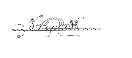
With reference to ~igs. 2 and 3, reclosable flexible
container 10 of the present invention is made of thermoplastic film
12 having continuous base layer 14 attached to the inner surface
thereof. Shown best in Fig. 1, continuous base layer 14 includes
integrally extruded means for gripping, preferably ribs 16, as
shown. First and second zipper elements 18, 20 attach to
2~48~
-- 10 --
continuous base layer 14 generally along opposite edges thereof.
Continuous base layer 14 serves to tie zipper elements 18, 20 to
the film and is also positioned to hermetically seal first and
second perforated lines of tearing 22, 24 provided in film 12.
First and second perforated lines of tearing 22, 24 permit easy-
opening of the flexible container 10. Tearing therealong removes
the top edge 26 of container 10, as well as contiguous portions of
continuous base layer 14 adhered thereto.
As shown in Figs. 1-5, a plurality of ribs 16 is
preferred, preferably eight, as shown in Fig. 8, covering an area
generally one-half inch wide on each opposing bag wall. A
plurality of ribs 16 enhances gripping of first and second bag lips
28, 30 after the top edge 26 of container 10 is removed.
Alternatively, means for gripping may be grooves, however, ribs 16
are preferred.
Alternative embodiments of container 10 of the present
invention are shown in Figs. 4 and 5. In Fig. 4 one of the
perforated lines of tearing, for example first perforated line of
tearing 22, extends through the continuous base layer 14 as well
asthrough the film 12, to enhance removal of top edge 26. In
accordance with the method of the present invention, the step of
perforating first perforated line of tearing 22 may occur after
continuous base layer 14 and zipper elements 18, 20 are attached to
film 12. This embodiment is not preferred, however, because the
perforation througll continuous base layer 14 eliminates the
hermetic seal of container 10.
The alternative embodiment of Fig. 4 also
representatively shows that seam 40 of container 10 may be formed
other than at the bottom of container 10, such as may be the case
on a horizontal packaging machine. Similarly, Fig. 4 shows that
continuous base layer 14 need not be adhered generally centrally
across film 12.
In the alternative embodiment of Fig. 5, continuous base
2û6~8~
layer 14 is shown attached to membrane 32 which, in turn, is
attached to bag body 34 of film 12 to form container 10. This
alternative embodiment permits the present invention to be
incorporated in a membrane 32, and membrane 32 later combined, when
cooled, the bag body 34 of container 10. In this embodiment,
membrane 32 is perforated and continuous base layer 14 is applied
thereto in accordance with the method of the present invention set
forth above with regard to film 12.
Base die 46 of the present invention is shown in more
detail in ~igs. 8 and 9. Referring to the preferred embodiment of
Fig. 8, base die 46 is comprised of three components: die body 66,
base plate 68, which defines the size of base opening 70 for
continuous base layer 14, and grip strip plate 72, which includes
a plurality of rib forming channels 74. Die body 66, base plate 68
and grip strip plate 72 are connected by bolts 76 as shown. Die
body 66 is typical of those known in the prior art, and is adapted
for operation at typical pressures, for example, approximately 1500
psi. In an alternative embodiment, a portion of base opening 70
may be included in grip strip plate 72 with rib forming channels
74. However, the flexibility of design, detailed below, is
compromised, and the alternative embodiment is not preferred.
In accordance with the preferred embodiment of the
present invention, by virtue of grip strip plate 72 being separable
from die body 66 and base plate 68, grip strip plate 72 may be
removed and replacedlwith a modified grip strip plate (not shown)
to increase the size, number, shape or location of ribs produced on
the surface of the continuous base layer 14. Similarly, the width
or height of the base opening 70 in base plate 68, preferably a
generally rectangular shape with sides approximately 4.0 to 4.5
inches wide and approximately 0.030 inches high, may be changed
without need to reform rib forming channels 74. Maximum
flexibility is thereby possible in adapting a single base die 46 to
provide a continuous base layer 14 with integral ribs 16 for
2~1481
- 12 -
various applications.
As shown best in Fig. 9, rib forming channels 74 taper
down to a point from their triangular shape on the face of grip
strip plate 72. Where extrusion of LDPE is carried out at
approximately 1500 psi, preferred dimensions of rib forming
channels would be substantially 0.10 inches high at the peak,
substantially 0.04 inches wide across the face of grip strip plate
72, and substantially 0.30 inches deep into base die 46 from the
face of grip strip plate 72. If a higher extrusion pressure is
used, the depth of the taper may be less, and where lower, the
taper must be deeper and more gradual. Thus, the dimensions of rib
forming channels 74 may be approximately 0.033 to 0.333 inches high
at the peak, approximately 0.013 to 0.133 inches wide across the
face of grip strip plate 72, and approximately 0.1 to 1.0 inches
deep into base die 46 from the face of grip strip plate 72.
Materials used to make base die 46, as well as other
apparatus components, and means for connecting the components of
the apparatuses disclosed and described are conventional, unless
otherwise indicated.
In the operation of base die 46 and the method of the
present invention, some iterative refinement of the parameters set
forth herein may be necessary to adapt particular apparatus
components used to achieve the results defined by the present
invention. ~s well, variation in the polymer output of base die
46, variation in the operating pressures of base die 46, the
dimensions of rib forming channels 74, the size of base opening 70,
the drawdown, and t}-e speed of film 70 is possible to vary the
dimensions of the ribs and continuous base layer 14 to adapt the
results to suit various applications.
2061q81
- 13 -
Thus, while certain representative embodiments and
details have been shown for purposes of illustrating the present
invention, it will be apparent to those skilled in the art that
various changes in the articles, apparatus and methods disclosed
herein may be made without departing from the scope of the
invention, which is defined in the appended claims.