Note: Descriptions are shown in the official language in which they were submitted.
` ~ 1 2~617~0
A MR~t-D ~Nn ARR7~ J~rrl FOR FINELY-GRINDING ~TNT~'RAT.!S
FOR USE A~ A FIT.T.Ti~R
The present invention relates to a method for finely-
grinding minerals and similar materials down to a parti-
cle size which will render the ground material suitable
for use as a filler, using herefor a mill in which the
minerals or like material are ground by means of an
agitated grinding medium and in which said minerals or
like material are ground while in a substantially dry
state. The invention also relates to a mill arrangement
for use when carrying out the inventive method.
Minerals and similar materials which are to be used as a
filler in the production of different products, for
example in the manuf acture of paper, plastics, paints,
coatings, adhesive products and sealing materials, must
have an average particle size which lies at least be-
neath 45 ,um (97%). Furthermore, it is necessary that
the material has a specific surface area corresponding
to a Blaine-number greater than 400 m /kg. In the
majority of cases, an average particle size smaller than
10 ~m is required, for instance when the materia~ is
used as a~filler in paper and paints, while certain
other applications require a still finer particle size,
so-called ultrafine particles having an average particle
size or grain size of <2 ~m, for example when used as
filler in paper coatings.
In certain cases, the f iller material used for these
purposes may comprise a precipitate which already has
the desired particle size, or a particle size which lies
close to the desired particle size, although filler
materials are normally produced by a grinding process
that includes a f ine grinding stage in which minerals or
I .
.. . .
2 20i~1~40
similar ~ natural materials are ground to a desired par~i
cle fineness. Standard materials from which fillers are
produced include dif;Eerent carbonate materials, such as
limestone or dolomite, different sulphate materials such
as gypsum, and silicon-based material, for example
clays, such as kaolin. Fine-grained products of this
kind cannot be readily produced by wet grinding pro-
cesses, such processes being those normally applied for
grinding minerals down to desired f ineness, since a wet-
ground product needs to be subsequently dried. The fine
material tends to lump together during this drying
process and the result agglomerates need to be broken
down in a f urther grinding process . The capital invest-
ment required heref or renders the wet grinding alterna-
tive prohibitive in the ma jority of cases . In conse-
quence, it is necessary to use a dry grinding process,
which in the present case implies a choice between a
roller mill or a mill which functions with an agitated
grinding medium. A rolling mill can only be used to
produce relatively coarse filler material, although it
feasibly possible to produce products having a grain or
particle size in the order of 3 ~m, when milling in
combination with air sieving, by circulating large
volumes of material through the mill.
So-called attrltion grinding has been proposed with the
aim of producing ultraf ine products . Attrition grinding
can be achieved in a mill operating with an agitated
grinding medium, as described in more detail herebelow.
The technique of grinding down material with the aid of
an agitated medium (Stirred Ball Milling) has been known
to the art for almost 60 years. The technique had its
industrial breakthrough in 1948, in conjunction with
pigment grinding in the paint and lacquer industry. The
technique has been developed progressively during recent
- ~ 3 20617~0
years and has obtained increased application. As a
result, many different types of grinding mills that use
an agitated medium have been proposed, as is evident,
for instance, from an article published in International
Journal of ~5ineral Processing, 22 (1988), pages 431-444.
One of these mills is equipped with pin agitator rotors
by means of which the requisite grinding energy is
introduced by forced displacement of the grinding
medium .
~ecause the mill is able to grind material rapidly down
to extremely fine-grain sizes, normally within the range
of 1-10 ,Lm, the technique of grinding with the aid of an
agitated medium has been applied to an increasing degree
for various types of material. For example, fine grind-
ing of this nature is applied in the production of fine- '-
grain products within the f ields of: paint and lacquer
technology, pharmacology, electronics, agrochemistry,
foodstuffs, biotechnology, rubber, coal and energy.
Examples of this latter case include coal-oil-mixtures
and coal-water-suspensions. The technique of grinding
with an agitated medium is now also being applied within
the mineral processing field. Examples of such applica-
tion include the grinding of limestone, kaolin, gypsum,
aluminium hydroxide and the manufacture of paper fillers
and paper coating materials, as before mentioned.
The results of experiments and tests carried out in
recent years have shown that when grinding with an
agitated grinding medium, the fineness of the ground
material is df~p~n-l~nt solely on the specific energy
input, which can be expressed in kWh/tonne of material
ground. Fur~h ~, it is found that the advantages
afforded by this grinding technique over the alternative
techniques is greatly ~nh~nc~cl with increasing fineness
of the ground material, in other words grinding with an
., , ~
4 20617~0
agitated grinding medium becomes more attractive with
the desired f ineness of the end product . Thus, a f iner
end product requires a higher specific energy input,
i . e . a higher specif ic power input and/or longer grind-
ing time. Obviously, it is preferred primarily to try
with a higher power input, so as not to negatively
influence the productivity of the mills concerned.
Grinding times of 6-8 hours, which have been suggested,
for instance, in conjunction with the grinding of py-
rites in South Africa, are naturally not so attractive,
although in many cases necessary, since a higher power
input would place even greater demands on the ability of
the mill to withstand a harsh environment, particularly
when grinding harder materials.
A suitable mill for grinding materials down to very
fine-grain sizes with a high power input is described in
our earlier Patent Specification SE-A-9000797-2.
However, a serious problem is encountered when finely-
grinding dry material in a mill that operates with an
agitated grinding medium, namely that large quantities
or volumes of material must be circulated in the process
and wind sieved, similarly to the case in other types of
dry grinding processes, as mentioned in the introduc-
tion. It is necessary to circulate through the mill up
to 200-300% of the product taken from the mill, in order
to obtain the desired f ine-grain product subsequent to
sieving. This is mainly due to the difficulties experi-
enced in controlling the stay time, or residence time,
in the mill in relation to power input and therewith to
the grinding energy per unit of weight, which is, in
turn, directly inf luenced by the grain size of the end
product. When wet grinding in mills of this kind, the
stay time can be readily controlled by controlling the
flow of ;nco--in~ and/or outgoing slurry, by means of the
5 2~1740
slurry pumps used.
There is therefore a great need, primarily in the manu-
facture of fillers, of an improved method for dry grind-
ing materials in mills which operate with an agitated
grinding medium, and capable of utilizing the technical
and economical advantages afforded by this type of mill,
by eliminating the necessity of circulating large vol-
umes of material through the mill. This would enable
flller materials to be produced for all conceivable
applications in a fashion which is attractive, both
technically and economically.
Accordingly, our earlier mentioned publication
SE-A-9003858-L teaches an improved method and an im-
proved arrangement for finely-grinding dry minerals and
similar materials intended for use as a filler, down to
grain sizes suitable for this purpose. According to
this method, the stay time of the material to be ground
is first de~Prm;nP-l with respect partly to the ingoing
particle size of the material and partly to the outgoing
grain size, and also ~o the grinding properties of the
material, which can often be rll~tPrm;npll empirically.
The material is then introduced into the mill in an
essentially dry state, by which i8 meant that the mois-
ture content of the material must not exceed about o . 5% .
The thus predetPrm; nPd stay time is maintained partly by
controlling and steering the infeed of material to the
mill such as to maintain said infeed as constant as
possible at a predetermined value, and partly by con-
trolling and steering the outfeed from the mill in a
manner which will keep the volume of material present in
the mill substantially constant at each moment in time.
The quantity of material present in the mill is deter-
mined by cont; n~ cl y weighing the mill together with
its content of grinding medium and the material being
6 20gl7~LO
ground . Any upward or downward deviation f rom a con-
stant value of this mass causes signals to be sent from
the weighing device to an outf eed valve, which in re-
sponse to said signals either decreases or increases the
flow of material exiting from the mill, such as to
return the mill content to said constant value.
This earlier method is thus based on the concept of
maintaining the material undergoing grinding in the mill
at a constant volume, as far as possible, during the
whole of the grinding process, thereby obtaining a
def ined energy input per unit of weight of material in
the mill, which is a measurement of the stay time of the
material in said mill and therewith also directly pro-
portional to the f; n~nes~:: of the ground material taken
from the mill .
In some cases, however, the process of continuously
monitoring variations in the total weight of the mill
has created problems. These problems are primarily
encountered in the case of large mill constructions and
in materials that are lighter in weight, where the
weight variations in time may be so small in relation to
the total weight as to render it difficult to record
these variations continuously to the desired degrees of
accuracy with the aid of commercially-available scales,
even though a weighting factor is used to account for
the weight of the mill.
It has now surprisingly been found possible to provide a
simple, alternative method and arrangement for finely-
grinding dry minerals and similar materials in which it
is not necessary to weigh the mill and its contents
continuously .
7 2061740
The inventive method and arrangement are characterized
by the method steps and the f eatures set f orth in the
following Claims.
Thus, present invention involves f irstly de~ i n i n~ the
stay time, or residence time, of the material present in
the mill and being f inely ground therein . This pre-
determined stay time, and therewith also the grinding
energy per unit of weight of material, is maintained
partly by discharging a predetermined, substantially
constant volume of ground material from the mill, and
partly by adjusting the volume of material fed to the
mill in relation to the volume of material discharged
from the mill such that the volume of material present
in the mill will increase during the mill charging
stage, i.e. the infeed stage. The infeed of ~material to
the mill is interrupted in response to a signal produced
by a level monitor mounted in the upper part of the
mill, i . e. when the level o~ material in the mill has
reached a highest, pr~ rmine~l level. This interrup-
tion in the infeed of material to the mill is maintained
during a prede~rmino-l, short period of time, e.g.
after, for example, a given time point or upon receipt
of a signal from a second level monitor located beneath
the first monitor.
The inventive method and arrangement will now be
described in more detail with reference to the accom-
panying drawing, the single Figure of which illustrates
the inventive method practiced with the aid of a pre-
ferred ` _'i~ L of the inventive arrangement.
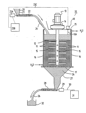
Shown in the Figure is a mill 10 which operates with an
agitated grinding medium 11 and which includes a rotor
12 which is driven by a motor 13 through the intermed-
iary Qf a planet gear 14. The rotor 12 is provided with
8 206~740
pins 15 which extend substantially perpendicular from
the rotor, in four different directions. The mill 10 is
cooled by a water-filled jacket 16, to and from which
water is continuously introduced and removed through
respective inlets and outlets marked with arrows and
reference H 0. Fitted to the bottom part of the mill 10
is a metal bottom plate 17 which is provided with
downwardly-conical, circular openings which are adapted
to hold the grinding media separate but which allow the
ground material to pass therethrough. Mounted on the
upper part of the mill 10 is a level monitor 18, which
may be provided with a fork sensor 18A.
Material 20 to be finely ground in the mill is fed, via
a hopper 21, through a screw feeder 22, the speed of
which is controlled so as to feed a predetermined quan-
tity of material to the mill with each unit of time,
said control being effected with the aid of a drive
means 23 comprised of a motor 23A and a speed-regulating
device 23B. When the material 20 in the mill 10 reaches
a highest permitted value, a signal is produced by the
level monitor 18 and transmitted on a line 23C, such
that the inf eed of material is interrupted subsequent to
the lapse of a given period of time after the monitor 18
has produced said signal. The level monitor 18 may
suitably be provided with a clock which automatically
produces a signal to r~ -n~-e loading of material into
the mill after a predet~ n~ period of time has
lapsed. The material 20 is charged to the mill 10
through a filling funnel 24. It is ensured that only
material 20 charged to the mill is present in the upper
part 25 thereof, whereas the L~ ; n~ of the mill 10
shall also include grinding medium 11. The ground
material, referenced 26, is sieved from the grinding
medium on the bottom plate 17 and is transported, in the
form of a coherent flow of material, through a funnel 27
9 2~6174~ ~
and to a motor-driven discha}ge device 28, which in the
illustrated case has the form of a screw feeder having a
continuously adjustable feeding speed. The screw feeder
28 is driven by a motor 29 whose speed can be controlled
by a control device 31, via a line 30. The control
device 31 may have the form of a variator or a frequency
converter .
In operation, the outflow of flnely-ground material 26
is first adjusted with the aid of the outfeed device 28,
the motor 29 and the control device 31. The flow of
ingoing material 20 is then adjusted by adjusting the
speed of the screw f eeder 22 with the aid of the drive
means 2 3A, B, so as to ensure that the level of the
material in the upper part 25 of the mill lo will in-
crease ln accordance with the selected inf eed of mate-
rial. When the infeed and outfeed flows of material
have been set and finely adjusted in the aforedescribed
manner, and the upper level of the material 20 reaches
the sensor 18A of the level monitor 18, a signal is sent
from the level monitor 18 to the speed-regulating device
23B, through the cable 23C, causing an interruption in
the inf eed of material 20 . Subse~uent to the lapse of a
given period of time, the device 23s receives a further
signal, in response to which the infeed of material is
continued. Ground material 26 is discharged through the
screw feeder 28 in an essentially constant, predeter-
mined flow during the whole of the grinding process,
this discharged, ground material 26 being collected in a
3 0 storage container 3 2 .