Note: Descriptions are shown in the official language in which they were submitted.
2~177~
C~BLl~ ~IAVING WATERBLOCKING PROVISIONS
E~ETWEEN LAY}3RS OF RELATI~ELY RIGID ~ND SUPPLE MATERIALS
Techrlical Field
This invention relates to a communications cable having
5 waterblocking provisions between layers of relatively rigid and relatively
supple materials.
Background of the Invention
In the cable industry, it is well known that changes in ambient
conditions lead to diffcrences in vapor pressure between the inside and the
10 outside of a plastic cablc jacket of a sheath systcm. This genera!ly operatesto diffuse moisture in a unidirectional manner from the outside of the cable
to the inside of the cable. Furt}lermore, water may enter the cable because
of damage to the sheath system which compromises the integrity of the
cable. For example, lightning or mechanical impacts may cause openings in
15 the sheath system of the cable to occur, allowing water to move toward a
core of the cable, and, if not controlled, to move longitudinally into splice
closures, for example.
In the prior art, various techniques have been used to prevent
the ingress of water through the sheath system of a cable and into the core.
20 For example, a metallic shield which often times is used to protect a cable
against electromagnetic interference is provided with a sealed longitudinal
seam. However, because lightning strikes may cause holes in the metallic
shield, it is not uncommon to include additional provisions for preventing
the movement of water longitudinally within the cable.
Filling materials have been used to fill cable cores and atactic or
flooding materials have been used to coat portions of cable sheath systems
to prevent the movement longitudinally thereof of any water which enters
the cable. Although the use of a rllling material causes housekeeping
problems, inhibits manufacturing line speeds because of the need to rlll
30 carefully interstices of the core and presents problems for rleld personnel
during splicing operations, for example, it continues to be used to prevent
entry of the water into the core.
Presently, many commercially available cables also include a
water-swellable tape. The tape is used to prevent the travel of water
35 through the sheath system and into the core as well as its travel
longitudinally along the cable to closures and termination points, for
~6~ 77~
e~;ample.
otllcl factor that must be considcled with rcspect to a
watel blocl;ing systcm for a cablc is the bonding of the plastic cable jacket
to an underlyillg metallic shicld. Where SllCh adhesion is important to the
5 performance of the cable, care must be taken not to intcrpose a
waterblocking member thcrebetween which would impair the desired
adhesion.
As a solution to the foregoing problerlls, a waterblocking member
in the form of a strip or a yarn whicll covers only an insubstantial portion
10 of an inner periphery of the cable may be used.
~ 'urther, the prior art discloses that a waterblocking member
may extend lincarly or helically along the cable. In an optical fiber cable in
which separate strength members extend linearly within the cable, the strip
or yarn may be wrapped helically about a core tube along an outer surface
15 of which extend the strength members. In an optical fiber cable in which
the strength members extend helically about the cable core, the yarn or
strip extends linearly or is wrapped in a helical direction opposite to ~hat of
the strength mernbers and is disposed between the strength members and
the core. See U.S. patent ~,~15,813.
In the last mentioned optical fiber cable, water may travel along
a helically or linearly extending channel formed along each helicaily or
linearly extending strength member. The water is intercepted at each pOil1t
at which a waterblocking yarn or strip crosses a strength member.
However, in metallic conductor cables, strength is provided by the metallic
25 conductors themselves and by metallic shields of the sheath system. In
those instances, any water is not channeled along helically or linearly
extending paths such as along the helically or linearly extending strength
members in optical fiber cables, but rather can travel along an annularly
shaped channel between adjacent components of the cable.
Another problem relates to a cable which includes an inner
jacket which may be used to cover a plastic core wrap material such as
Mylar~ plastic, for example. If a metallic shield is contiguous to the plastic
core wrap material, the core wrap material may be flooded with an atactic
material for waterblocl;ing purposes. Here again such materials as atactic
35 flooding compounds are not popular with craftspeople who at some future
time may have to reenter the cable and be faced with housekeeping
2 ~ 7 ~
~ 3 -
prol)lclns. On tllc olllcr harl(l, ir an inner jacket is interposed between the
COI'C wrap and thc mcl-Lllic shield, it becomes difrlcult ~,o cxtrude a jacket
having a ullifol lll thickness ovcr the flooding material. Furtherrnore, lumps
could appear in the jacket, caused by uneven masses of the underlying
5 flooding material.
Seemingly, the prior art does not disclose a cable which is
provided with a system which prevents substantially the flow of water
longitudinally along a cable sheath system which has no helically or linearly
extending strength members and in whlch a plastic jacket is to be extruded
10 directly over a relatively supple plastic core wrap. What is needed and what
àoes not appear to be available in the marketplace is a cable waterblocking
system which is relatively ille~pensive and which does not add significantly
to the diameter of the cable. Such a system should be one which is easily
provided during the cable manufacturing process.
15 Summary of the Invention
According to the invention, there is provided a cable as set out
in claim 1.
Brief Description of the Drawin~
FIG. 1 is a perspective view of a communications cable having a
20 sheath system which includes a waterblocking system with various layers of
the sheath system bro~en away and some of the layers e~aggerated in
thickness for purposes of clarity;
FIG. 2 is an end sectional view of the cable of FIG. 1 which
illustrates some elements of the cable in greater detail;
FIG. 3 is a perspective v;ew of a cable which includes a core
wrapped with a relatively supple plastic material, for example, and having
yarns wrapped thereabout w;th a plastic jacket disposed about the yarns;
and
FIG. 4 is an end sectional view of the cable of FIG. 3.
30 Detailed Description
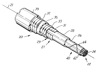
Referring now to FIGS. 1 and 2, there is shown a
communications cable which is designated generally by the numeral 20.
The cable 20 has a longitudinal axis 21 and includes a core 22 cornprising
one or more transmission media such as one or more pairs of insulated
35 metallic conductors 2'1-24 and is ~llled with a suitable waterblocking
material 25. About the core is disposed a relatively fle~;ible layer 26 of
2~3~ 77~
pl.lst,iC IllatCl`ial ~-'hich OftCII iS rrcrlcd to as a corc wrap. Typically, tlle
l.lyel 2G tyl)ically COlllpi'iSCS a slrip of polyetl1ylene terepht}laiate plastic
material, for exarmple, which has been wrapped about the core in a manner
to form a longitudinally extending seam.
S About the core wrap layer is disposed a sheath system 27 which
includes a relatively rigid inner jacke~ 28 which is made of a plastic
material and whicl1 encloses the core wrap and the insulated metallic
conductors. Typically the inner jacket 28 is extruded over the core wrap
layer 2B and comprises polyethylene.
A corr-lgated inner metallic shield system 29 is clisposed about
the inner jacket 28. As can be scen in FIGS. 1 and 2, the inner shield
system 2~3 compriscs a corrugated aluminum shicld 31 whieh has been
wrapped longitudinally about the core to form a gapped seam, which is
exaggerated for purposes of clar;ty in FIG. 1, and a corrugated steel shield
15 33 which has a longitudinal overlapped seam.
An intermediate plastic jacl;et 35 is disposed about the
corrugated steel shield. Typically, the intermediate jacket 35 comprises
polyethylene plastic material.
The sheath system 27 also includes an outer corrugated steel
20 shield 37 having a longitudinal overlapped seam and a plastie outer jacket
39. Typically, the outer plastic jacket 39 also comprises polyethylene
plastic material.
In cables of this invention, additional provisions are made for
preventing the flow of water longitudinally along the cable into elosures. In
25 the cable 20, water may travel within the cable between the core wrap layer
26 and the inner jacket. Between the eore wrap layer 26 and the inner
jacket 28 is disposed a water blocking system 40. Such water flow is
prevented substantially by causing yarns which cover only an insubstantial
portion of the periphery of the core wrap layer 26 to be disposed between
30 the core wrap layer and the inner jacket 28.
The water blocking system ~10 comprises yarns 42 and 44 (see
FIG. 1), each of which includes a water-swellable material. The yarns 42
and ~4, although identical in structure and composition, extend helically in
opposite directions about the layer 26. The wrapping is such that about
35 three turns of cach yarn are included in each meter of cable length.
2~1 r~7r,
- -
I`lle yarIl also must be characterized by suital)le water
ahsorbcllcy an(l rclclltivity. In ordcr to render thc yarns 42 and ~14
swcllable u})on contact wilh moislure, the yarn of the preferred embodiment
is comprised of a plurality Or rlbers each of which has becn treated
5 chemically ~ith a suitable water swellable material which herein is referred
to as a supcrabsorbent material.
Superabsorbents are hydrophilic rnaterials which can absorb and
retain water under prcssure without dissolution in the fluid being absorbed.
See J. C. Djock and R. E. I~lern "Review of Synthetic and Starch-Graft
10 Copolymer Superabsorbents" prepared for the Absorbent rroducts
Conference held Novcmber 16-17, 1~383 in San Antonio, Texas and
incorporated by reference hereinto. Properties such as enzyme stability,
biodegradability, absorbent capacity and rate of uptake are used to
characterize a superabsorbent material. One of the early superabsorbents
15 was a saponified starch graft polyacrylonitrile copolymer. See U.S. patent
3,425,971. The above-identifiecl patent disclosed saponifying starch-graft
polyacrylonitrile copolymers with aqueous bases.
The two major superabsorbents which are available today are
cellulosic or starch-graft copolymers and synthetic superabsorbents. There
20 are two major broad classes of synthetic superabsorbents. These are the
polyelectrolytes and the nonelectrolytes. The polyelectrolytes are the most
important and fall into four classes- polyacrylic acid superabsorbents,
polymaleic anhydride-vinyl monomer superabsorbents, polyacrylonitrile-
based superabsorbents and polyvinyl alcohol superabsorbents. Of these, the
25 polyacrylic acid and polyacrylonitrile-based superabsorbents are the most
common. As with cellulosic-~raft copolymer superabsorbents, the capacity
of synthetic superabsorbents decreases with increasing salinity.
The polyacrylic acid class of superabsorbents includes both
homopolymers and copolymers of acrylic acids and acrylate esters. The
30 monomer units usually are polymerized to produce a water-soluble polymer
which is then rendered insoluble by ionic and/or covalent cross-linking.
Cross-linking of the polymer may be accomplished with a multivalent
cation, radiation, or with a cross-linking agent. The absorbency of the
product is determinecl by the number of ionizable groups, usually
35 carboxylates, and the cross-linking density.
2 ~ 7 ~
'I`hc crOss~ g (lcnsity arfects not ollly the al)solberlcy, b~lt
also thc tirne il takcs to absorb and the strcngtll of tlle gel formed.
Gcnerally, the higher tlle cross-linking density, thc stronger is the gel which
is forme(l. The time to reach absorbent capacity decreases as the cross-
5 linking density increases, and the absorbent capacity decreases.
The yarns 42 and ~4 may be imprcgnated with any of severalwatcr blocking superabsorbent materials. They may be impregnated with a
superabsorbent material which is dcrived from an aqueous solution
comprising acrylate polymeric material which combines acrylic acid and
10 sodium acrylate functionalities and water. The impregnating material may
comprise a sodium salt of polyacrylic acid in which all the carboxylic groups
may or may not be rcacted with sodium. In other words, it is saponi~led in
whole or in part. The level of saponification which may fall within a
relatively wide range depends on desired properties. After the yarn has
15 been impregnated, the superabsorbent material is dried to provide a rllm on
the center fiber yarn.
In another embodiment, a yarn is impregnated with an aqueous
solution comprising acrylates and acrylamide polymer powders mixed with
water. In each of the cmbodiments just described, the impregnating
20 material is a mixture of water and a superabsorbent material in which the
mixture comprises about 4 to 7'~70 solids when the impregnating material is
an aqueous solution and applied.
In general, the yarns 42 and 44 may be impregnated with (1) a
material comprising polyacrylic acid, (2) a material comprising
25 polyacrylamide (3) blends of (1) and (2) or salts thereof or (4) copolymers of
acrylic acid and acrylamides and salts thereof as well as other similar
superabsorbent materials.
In the preferred embodiment, each yarn 42 and 44 is comprised
of treated fibers. Each treated fiber comprises an inner member which
30 comprises about 70~o by weight of the treated fiber and which comprises
polyacrylonitril and an outer layer of superabsorbent material. In a
preferred embodiment, the fibers of each yarn are 5 denier. The outer layer
of superabsorbent material of the preferred embodiment comprises about
9~o by weight of the treated fiber of polyacrylic acid and about 21% by
35 weight of polyammonium acrylate. Such a yarn is disclosed in U.S. patent
4,36B,206 which is incorporated by reference hereinto. Yarn suitable for use
~ ~J ~ ~ 7 ~ ~
,
il~ a cal!le 2() is ln"lluf~lctllle(l by 'I'oyoho, l,t(l. of C).cial~a, Japan, unàcr the
tra~lc dcsiglln~il)n "I,~nscal-l~`" supclabsol bcnt rll)cr and is available
COmlllCrCiall~' frOIll Chori ~llleriCa, 113C. Treatcd 5 denier x 51 rnm l~lbers
wllicll complise a yaln Or tlle prefcrlcd cmbo(lilnellt are characterized by a
5 ~ ater al>solbency in distillccl watel of 150 ml/g and in 0.~)% NaCI solut;on
of 50 ml/g. Water rcterltivity Or sucil a fibcr under weight for a 1% NaCl
sol~tion is 20 ml/g and ils moisture content when slliT)ped is no greater than
7~. I~ach fiber is chalacterizcd by a tcnsile strength (dry) of at least 1.6
g/d alld an clongation (dly) of 15 to 25~o. Thcse properties appear in a
10 bulletin entitled "I,anseal-F" supcral)sorbcnt rlber.
Each yar n 92 and 9 l lnust be cllaracterized by other properties.
For example, bccause the y arn is to be cmbodicd in a cable, it is benerlcial
for thc yarn to have a rclativcly high tcnsilc strength. For the prefcrred
embodiment each yarn has a tensile strength of about 4.5 kg.
Advantagcously, in rcsponse to contact with water, the
supcrabsorbent n~aterial in a cable structure swells to block the flow of
watcr in a longitudinal direction. When the yarn is contacted by water, the
outer layer of each fiber swclls signirlcantly by imbibing w ater. The
superabsorbel1t material also forms a gel and changes the viscosity of the
20 ingrcssed water at the point of contact with the superabsorbent material,
making it more viscous and consequently developing more resistance to
water flow. As a result, the flow of water longitudinally along a cable from
a point of entry is reduccd substantially.
It will be recalled that unlike some optical fiber cables, the cable
25 20 does not include separate strength members which extend helically or
longitudinally along the cable so that a single hclically extending yarn
intercepts water at crossover points with the strength members. In order to
intercept water which may flow along a channel formed by any one yarn,
the cable 20 of this invention includes two water blockable yarns. Further,
30 as is seen in FIG. 1 the yarns 42 ancl 49 are wound helically in opposite
directions about the core wrap layer 26.
The waterblocking systcm in any given plane transverse of the
longituclinal axis 21 of the cable extends about only an insubstantial portion
of an inner periphery of the cable in that plane. There is substarltially no
35 incrcase in the diameter of the cable because of the presence of the yarns 42 and 49. Also, the yarns 42 and 94 are substantially less in cost than a
7 ~
t3
systetn i~ ich a slrip Or wal,erl)lockin6 rnaterial or atactic flooding
matcrial is uscd.
The watcrblocking systcm ~10 Or the cable of this invention
facilitatcs thc c~trusion of lhe inl1cr jacket 28. Inasmuch as the use of an
5 atactic material between the core wrap layer ~G and the inner jacket 28 has
been elil-llinated and rcplaced by helically cxtendlng yarns which occupy a
relatively small portion of the circ~lmference, the inner jacket is extruded
over a relatively smooth sllrface. ~s a result, the inner jacket has a
relatively uniform thickness and does not exhibit protruding portions.
C~oing now to ~IGS. 3 and 4, there is shown a cable 50 which
includes a core 52 which comprises one or more pairs of plastic insulated
metallic conductors 53-53. The core 52 may be rllled with a waterblocking
material. A plastic core wrap layer 5'1 of a relatively flexible material has
been wrapped about the core and a plastic jacket 56 which typically is
15 comprised of polyethylene is disposed about the core wrap layer 64.
Interposed between the core wrap layer 54 and the jacket 56 are two yarns
60 and 62 which extend in opposite helical directions about the core wrap
layer. Each of the yarns may be identical to the yarns of the cable of FIG.
1 or may be comprised of other materials having suitable strength and
20 waterblocking properties.
It is to be understood that the above-described arrangements are
simply illustrative of the invention. Other arrangements may be devised by
those skilled in the art which will embody the principles of the invention
and fall within the spirit and scope thereof.