Language selection

Search

Patent 2061864 Summary

Third-party information liability

Some of the information on this Web page has been provided by external sources. The Government of Canada is not responsible for the accuracy, reliability or currency of the information supplied by external sources. Users wishing to rely upon this information should consult directly with the source of the information. Content provided by external sources is not subject to official languages, privacy and accessibility requirements.

Claims and Abstract availability

Any discrepancies in the text and image of the Claims and Abstract are due to differing posting times. Text of the Claims and Abstract are posted:

  • At the time the application is open to public inspection;
  • At the time of issue of the patent (grant).
(12) Patent: (11) CA 2061864
(54) English Title: DEVICE FOR MOVING LARGE AND HEAVY LOADS
(54) French Title: DISPOSITIF UTILISE POUR DEPLACER DES CHARGES LOURDES ET DE DIMENSIONS CONSIDERABLES
Status: Expired and beyond the Period of Reversal
Bibliographic Data
(51) International Patent Classification (IPC):
  • B65G 7/02 (2006.01)
  • B66F 1/08 (2006.01)
  • F16C 29/02 (2006.01)
(72) Inventors :
  • LUSSIER, MICHEL (Canada)
(73) Owners :
  • 2866-0322 QUEBEC INC.
(71) Applicants :
  • 2866-0322 QUEBEC INC. (Canada)
(74) Agent: ROBIC AGENCE PI S.E.C./ROBIC IP AGENCY LP
(74) Associate agent:
(45) Issued: 1996-08-27
(22) Filed Date: 1992-02-26
(41) Open to Public Inspection: 1993-08-27
Examination requested: 1992-02-26
Availability of licence: Yes
Dedicated to the Public: N/A
(25) Language of filing: English

Patent Cooperation Treaty (PCT): No

(30) Application Priority Data: None

Abstracts

English Abstract


A device for moving large and heavy apparatuses combining
modular rail sections positioned one after the other to form
two parallel rails onto which slides a load-carrying plate
extending transversally between the rails. The upper
surface of the rail section has a central row of upwardly
projecting supporting elements positioned at regular
intervals along its length. The undersurface of the carrying
plate has two opposite edge portions each having two
parallel rows of guiding elements projecting down and
positioned at regular intervals along its length. When the
plate is positioned on top of the rails, the two rows of
guiding elements define a guiding channel which may
releasably engage the central row of supporting elements
projecting up the corresponding rail. The upper layer of
each supporting elements and the bottom layer of each
guiding elements are made of a friction material, either low
friction material to facilitate movement therealong or high
friction material to enhance friction. Also, the central
row of supporting elements of the rails are sized to act as
retaining means for a hydraulic jack to push the carrying
plate.


Claims

Note: Claims are shown in the official language in which they were submitted.

The embodiments of the invention for which an exclusive
right of privilege or property is claimed are defined as
follows:
1. A device for moving a heavy load, said device
comprising, in combination:
- modular rail sections that can be assembled to form a pair
of parallel rails of a given length, each of said rail
sections comprising an upper surface from which upwardly
projects a row of supporting elements extending centrally at
regular intervals along the length of said rail sections,
each of said supporting elements comprising an upper layer
made of a friction material;
- a load-carrying plate sized to extend transversally
between said rails, said plate being movable along said
rails and having an undersurface with two opposite edge
portions overlying said rails, each of said edge portions
comprising two parallel rows of guiding elements projecting
down from the undersurface, said guiding elements being
positioned at regular intervals and each comprising a bottom
layer made of a friction material, said rows of guiding
elements being positioned and sized to define therebetween
a guiding channel in which may releasably engage said
central row of supporting elements projecting up the
corresponding rails; and
- hydraulic jack for incrementally pushing said heavy loads
positioned on top of said plate along said rails;
- wherein said supporting elements and guiding elements are
of the same height and cooperate for guiding said load-

carrying plate along said rails; and
- whereby, upon engagement of said plate on said rails, the
bottom layers of said guiding elements bear on said upper
surface of said rail sections on both sides of said rows of
supporting elements and the upper layers of said supporting
elements bear on the undersurface of said plate in said
guiding channels, thereby facilitating sliding of said plate
and load on said rails.
2. A device according to claim 1, wherein said supporting
elements are positioned and sized to act as retaining means
for said hydraulic jack.
3. A device according to claim 1 or 2, wherein the upper
layers of said supporting elements and the bottom layers of
said guiding elements are in the form interchangeable pads
detachably fixed to said elements.
4. A device according to claim 3, wherein said
interchangeable pads are made of a low friction material to
reduce friction between said rail and said load carrying
plate.
5. A device according to claim 4, wherein said low friction
material is made of very high molecular weight plastic.
6. A device according to claim 3, wherein said
interchangeable pads are made of a high friction material to
enhance and control friction between said rail and said load
carrying plate.

Description

Note: Descriptions are shown in the official language in which they were submitted.


- 2061864
DEVICE FOR HOVING LARG~ AND ~AVY LOADS
The present invention relates to a device for carrying and
moving loads that are heavy and large. More particularly,
the invention relates to a combination of two rails and a
sliding plate that is movable along these rails by the
action of a hydraulic jack.
D~Sr~TPTION OF THE PRIOR ART
Objects that weight several hundred tons such as
transformers, machines and the like may be extremely large
and bulky to transport. Since these devices must be moved
with precision to place them where they must be installed,
proper control over the movement of such devices is time
consuming and requires complex devices with high demands in
energy because the friction for moving such objects is
great.
It is therefore one object of this invention to provide an
improved device which can be used to move large and heavy
apparatuses while installing or relocating the same.
It is a further object of this invention to provide a
modular system for moving such large and heavy apparatuses,
these modules being portable and easy to carry from one
location to the next.
It is a further object of this invention to provide a device
for moving large and heavy apparatuses where the degree of
friction between the rails and the carrying plate can be
changed at will.
.~

2061~64
It is a further object of this invention to provide a device
for moving large and heavy apparatuses where the surface
contact of the rail and the plates that slide against each
other can be made of high friction or low friction material
in the form of interchangeable pads.
SUMHARY OF THE INVENTION
The above-mentioned objects are attained with a device for
carrying heavy loads, the device comprising in combination:
- modular rail sections that can be assembled to form a pair
of parallel rails of a given length, each of the rail
sections comprising an upper surface from which upwardly
projects a row of supporting elements extending centrally at
regular intervals along the length of the rail sections,
each of the supporting ele~ents comprising an upper layer
made of a friction material;
- a load-carrying plate sized to extend transversally
between the rails, the plate being movable alang the rails
and having an undersurface with two opposite edge portions
overlying the rails, each of the edge portions comprising
two parallel rows of guiding elements projecting down from
the undersurface, the guiding elements being positioned at
regular intervals and each comprising a bottom layer made of
a friction material, the rows of guiding elements being
positioned and sized to define therebetween a guiding
channel in which may releasably engage the central row of
supporting elements projecting up the corresponding rails;
and

- 2061~64
- hydraulic 3ack for incrementally pushing the heavy loads
positioned on top of the plate along the rails;
- wherein the supporting elements and guiding elements are
of the same height and cooperate for guiding the load-
carrying plate along the rails: and
- whereby, upon engagement of the plate on the rails, the
bottom layers of the guiding elements bear on the upper
surface of the rail sections on both sides of the rows of
supporting elements and the upper layers of the supporting
elements bear on the undersurface of the plate, in the
guiding channels thereby facilitating sliding of the plate
and load on the rails.
IN TH~ DRAWINGS
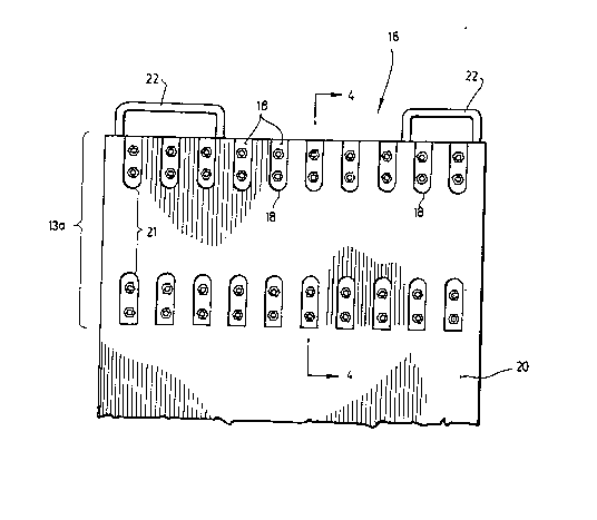
Figure 1 is a top plan view of the modular rail sections of
the invention when assembled to form two parallel rails;
Figure 2 is a bottom plan view of a portion of the load-
carrying plate according to the invention;
Figure 3 is a cross section view of one rail section of
Figure 1 as cut along line 3-3;
Figure 4 is a cross section view of the plate of Figure 2 as
cut along line 4-4: and
Figure 5 is an elevational view of the device of the
invention, when a hydraulic jack is retained between the
supporting elements of the rail sections according to the

-- 2061864
invention.
DRT~TJ~ D~SCRIPTIQN OF ON~ EXA~P~ OF ~ PR~F8RR~D
ENBODIMENT
Figure 1 shows a partial assembly of modular rail sections
10, having a length much larger than its width, and a width
much larger than its thickness. These sections 10 can be
assembled one end adjacent to another section's end to form
a rail of variable length depending on the number of
sections positioned one after the other. These modular
sections 10 are adapted to be positioned on top of
conventional rails or to be assembled on top of a series of
transversal dormants. These modular sections 10 when
assembled one after the other are to be positioned in two
parallel longitudinal rails 15a and 15b. These sections 10
have an upper surface 12 from which upwardly projects a row,
preferably a central row, of supporting elements 14
positioned at regular intervals along the length of the
rail. Each supporting element comprises a middle layer 28,
and an upper layer 30.
Figure 2 shows a portion of a load carrying plate 16 that is
sized to extend transversally between the rails 15a and 15b.
The plate 16 has an undersurface 20 having two opposite edge
portions 13a and (13b not shown) overlying the rails 15a and
15b (not shown) respectively. The plate 16 is movable along
these rails and each opposite edge portion 13a (or 13b) is
guided therealong by two parallel rows of guiding elements
18 that project down from the undersurface 20, each guiding
element 18 being positioned at regular intervals. The
guiding elements 18 are positioned and sized so as to define

- 2~61864
in between them a guiding channel 21.
Both the rail sections 10 and the load carrying plate 16
comprise handles 24 and ~2 respectively for helping users to
add or remove them from this assembly.
As shown in Figure 3, the supporting elements 14 of the
modular rail section 10 comprise a middle layer 28 and an
upper layer 30 that projects upwardly from the upper surface
12 of the section 10. The middle layer 28 and upper layer 30
are in the form of pads, and the upper pad 30 is made of a
friction material, preferably of low friction material such
as very high molecular weight plastic, or of a high friction
material such as steel. These pads 28 and 30 are eecured
with screws 32 that may be untightened to separate the pads
30 from the middle layer 28 to allow user to replace the
upper layer 30 after it is worn or to ~hange for another
friction material.
Figure 4 shows the load carrying plate 16 with its rows of
guiding elements 18 projecting downwardly from the
undersurface 20, the space between each row defining the
guiding channel 21. The two rows of supporting elements 14
releasably engage in the guiding channel 21 when the plate
16 is positioned on top of the rail 15a. The guiding
elements 18 comprise a middle layer 36 of steel, and a
bottom layer 38 that is made out of a friction material,
preferably low friction material such as very high molecular
weight plastic or high friction material such as steel. The
middle layer 36 and bottom layer 3B are in the form of pads
secured to the body 34 of the plate by screws 40 that may be
untightened to separate the pads 36 and 38 and allow a user

- 2061864
to replace the bottom layer 38 after it is worn or to change
the friction material.
As may also be seen from Figures 3 and 4, once the carrying
plate 16 is positioned on top of the rail 15a, the only
surfaces that will come in contact with each other are the
undersurface ~0 of the carrying plate 16 with the upper
layer 30 of the supporting elements 14 of the rail 15a, and
the upper surface 12 of the rail 15a with the bottom layer
38 of the guiding elements 18 of the carrying plate 16.
Of course, to attain this, the abutting elements 14 must be
of the same height as the guiding elements 18. Also, it is
to be understood that the abutting elements 14 may be
positioned in two parallel rows, whereas the guiding
elements 18 may be positioned in one central row to attain
the same effect.
This system allows a user to reduce the friction during the
sliding of the carrying plate 16 since no two steel surfaces
touch each other. Moreover, since the upper layer 30 and
bottom layer 38 are easily replaceable, it does not
constitute a problem if the high molecular weight plastic
wears out since these modular supporting elements 14 and
guiding elements 18 may easily be replaced.
Again, this system permits the removal of low friction
material and replacement by upper and bottom pads made out
of steel (a higher friction material) allowing the user to
control the friction of the two surfaces sliding against
each other.

2061864
Finally, as shown in Figure 5, this system is made in such
a fashion so that the supporting elements 14 of the rail
sections may serve as retaining means for the hydraulic jack
42 that incrementally pushes the heavy load. This jack 42
comprises a plurality of feet 44 sized so that they may be
positioned snugly between two abutting elements 14 and
therefore secure the hydraulic jack 42 in fixed position
when it is used to push the load.

Representative Drawing
A single figure which represents the drawing illustrating the invention.
Administrative Status

2024-08-01:As part of the Next Generation Patents (NGP) transition, the Canadian Patents Database (CPD) now contains a more detailed Event History, which replicates the Event Log of our new back-office solution.

Please note that "Inactive:" events refers to events no longer in use in our new back-office solution.

For a clearer understanding of the status of the application/patent presented on this page, the site Disclaimer , as well as the definitions for Patent , Event History , Maintenance Fee  and Payment History  should be consulted.

Event History

Description Date
Time Limit for Reversal Expired 2009-02-26
Letter Sent 2008-02-26
Inactive: IPC from MCD 2006-03-11
Letter Sent 2000-02-03
Letter Sent 1999-12-23
Grant by Issuance 1996-08-27
Application Published (Open to Public Inspection) 1993-08-27
All Requirements for Examination Determined Compliant 1992-02-26
Request for Examination Requirements Determined Compliant 1992-02-26

Abandonment History

There is no abandonment history.

Fee History

Fee Type Anniversary Year Due Date Paid Date
MF (patent, 6th anniv.) - small 1998-02-26 1998-02-11
MF (patent, 7th anniv.) - small 1999-02-26 1999-02-15
Registration of a document 1999-08-23
MF (patent, 8th anniv.) - small 2000-02-28 2000-02-14
MF (patent, 9th anniv.) - small 2001-02-26 2001-01-31
MF (patent, 10th anniv.) - small 2002-02-26 2001-12-07
MF (patent, 11th anniv.) - small 2003-02-26 2003-01-24
MF (patent, 12th anniv.) - small 2004-02-26 2004-01-05
MF (patent, 13th anniv.) - small 2005-02-28 2005-02-08
MF (patent, 14th anniv.) - small 2006-02-27 2006-01-17
MF (patent, 15th anniv.) - small 2007-02-26 2007-02-19
Owners on Record

Note: Records showing the ownership history in alphabetical order.

Current Owners on Record
2866-0322 QUEBEC INC.
Past Owners on Record
MICHEL LUSSIER
Past Owners that do not appear in the "Owners on Record" listing will appear in other documentation within the application.
Documents

To view selected files, please enter reCAPTCHA code :


To view images, click a link in the Document Description column. To download the documents, select one or more checkboxes in the first column and then click the "Download Selected in PDF format (Zip Archive)" or the "Download Selected as Single PDF" button.

List of published and non-published patent-specific documents on the CPD .

If you have any difficulty accessing content, you can call the Client Service Centre at 1-866-997-1936 or send them an e-mail at CIPO Client Service Centre.


Document
Description 
Date
(yyyy-mm-dd) 
Number of pages   Size of Image (KB) 
Abstract 1993-12-04 1 33
Description 1993-12-04 7 242
Cover Page 1993-12-04 1 14
Drawings 1993-12-04 4 66
Claims 1993-12-04 2 72
Claims 1996-08-27 2 78
Description 1996-08-27 7 257
Abstract 1996-08-27 1 35
Cover Page 1996-08-27 1 12
Drawings 1996-08-27 4 60
Representative drawing 1999-02-18 1 16
Courtesy - Certificate of registration (related document(s)) 1999-12-23 1 115
Courtesy - Certificate of registration (related document(s)) 2000-02-03 1 115
Maintenance Fee Notice 2008-04-08 1 172
Fees 2003-01-24 1 30
Fees 2004-01-05 1 30
Fees 1999-02-15 1 34
Fees 2001-12-07 1 31
Fees 1998-02-11 1 42
Fees 2000-02-14 1 30
Fees 2001-01-31 1 32
Fees 2005-02-08 1 27
Fees 2006-01-17 1 31
Correspondence 2007-01-10 3 105
Fees 2007-02-19 1 43
Fees 1996-01-22 1 44
Fees 1997-01-31 1 41
Fees 1995-02-08 1 48
Fees 1994-01-12 1 36
PCT Correspondence 1999-10-22 1 40
PCT Correspondence 1999-08-23 2 58
PCT Correspondence 1996-06-18 1 33
Courtesy - Office Letter 1999-08-24 1 22