Sélection de la langue

Search

Sommaire du brevet 2061864 

Énoncé de désistement de responsabilité concernant l'information provenant de tiers

Une partie des informations de ce site Web a été fournie par des sources externes. Le gouvernement du Canada n'assume aucune responsabilité concernant la précision, l'actualité ou la fiabilité des informations fournies par les sources externes. Les utilisateurs qui désirent employer cette information devraient consulter directement la source des informations. Le contenu fourni par les sources externes n'est pas assujetti aux exigences sur les langues officielles, la protection des renseignements personnels et l'accessibilité.

Disponibilité de l'Abrégé et des Revendications

L'apparition de différences dans le texte et l'image des Revendications et de l'Abrégé dépend du moment auquel le document est publié. Les textes des Revendications et de l'Abrégé sont affichés :

  • lorsque la demande peut être examinée par le public;
  • lorsque le brevet est émis (délivrance).
(12) Brevet: (11) CA 2061864
(54) Titre français: DISPOSITIF UTILISE POUR DEPLACER DES CHARGES LOURDES ET DE DIMENSIONS CONSIDERABLES
(54) Titre anglais: DEVICE FOR MOVING LARGE AND HEAVY LOADS
Statut: Périmé et au-delà du délai pour l’annulation
Données bibliographiques
(51) Classification internationale des brevets (CIB):
  • B65G 7/02 (2006.01)
  • B66F 1/08 (2006.01)
  • F16C 29/02 (2006.01)
(72) Inventeurs :
  • LUSSIER, MICHEL (Canada)
(73) Titulaires :
  • 2866-0322 QUEBEC INC.
(71) Demandeurs :
  • 2866-0322 QUEBEC INC. (Canada)
(74) Agent: ROBIC AGENCE PI S.E.C./ROBIC IP AGENCY LP
(74) Co-agent:
(45) Délivré: 1996-08-27
(22) Date de dépôt: 1992-02-26
(41) Mise à la disponibilité du public: 1993-08-27
Requête d'examen: 1992-02-26
Licence disponible: Oui
Cédé au domaine public: S.O.
(25) Langue des documents déposés: Anglais

Traité de coopération en matière de brevets (PCT): Non

(30) Données de priorité de la demande: S.O.

Abrégés

Abrégé anglais


A device for moving large and heavy apparatuses combining
modular rail sections positioned one after the other to form
two parallel rails onto which slides a load-carrying plate
extending transversally between the rails. The upper
surface of the rail section has a central row of upwardly
projecting supporting elements positioned at regular
intervals along its length. The undersurface of the carrying
plate has two opposite edge portions each having two
parallel rows of guiding elements projecting down and
positioned at regular intervals along its length. When the
plate is positioned on top of the rails, the two rows of
guiding elements define a guiding channel which may
releasably engage the central row of supporting elements
projecting up the corresponding rail. The upper layer of
each supporting elements and the bottom layer of each
guiding elements are made of a friction material, either low
friction material to facilitate movement therealong or high
friction material to enhance friction. Also, the central
row of supporting elements of the rails are sized to act as
retaining means for a hydraulic jack to push the carrying
plate.

Revendications

Note : Les revendications sont présentées dans la langue officielle dans laquelle elles ont été soumises.


The embodiments of the invention for which an exclusive
right of privilege or property is claimed are defined as
follows:
1. A device for moving a heavy load, said device
comprising, in combination:
- modular rail sections that can be assembled to form a pair
of parallel rails of a given length, each of said rail
sections comprising an upper surface from which upwardly
projects a row of supporting elements extending centrally at
regular intervals along the length of said rail sections,
each of said supporting elements comprising an upper layer
made of a friction material;
- a load-carrying plate sized to extend transversally
between said rails, said plate being movable along said
rails and having an undersurface with two opposite edge
portions overlying said rails, each of said edge portions
comprising two parallel rows of guiding elements projecting
down from the undersurface, said guiding elements being
positioned at regular intervals and each comprising a bottom
layer made of a friction material, said rows of guiding
elements being positioned and sized to define therebetween
a guiding channel in which may releasably engage said
central row of supporting elements projecting up the
corresponding rails; and
- hydraulic jack for incrementally pushing said heavy loads
positioned on top of said plate along said rails;
- wherein said supporting elements and guiding elements are
of the same height and cooperate for guiding said load-

carrying plate along said rails; and
- whereby, upon engagement of said plate on said rails, the
bottom layers of said guiding elements bear on said upper
surface of said rail sections on both sides of said rows of
supporting elements and the upper layers of said supporting
elements bear on the undersurface of said plate in said
guiding channels, thereby facilitating sliding of said plate
and load on said rails.
2. A device according to claim 1, wherein said supporting
elements are positioned and sized to act as retaining means
for said hydraulic jack.
3. A device according to claim 1 or 2, wherein the upper
layers of said supporting elements and the bottom layers of
said guiding elements are in the form interchangeable pads
detachably fixed to said elements.
4. A device according to claim 3, wherein said
interchangeable pads are made of a low friction material to
reduce friction between said rail and said load carrying
plate.
5. A device according to claim 4, wherein said low friction
material is made of very high molecular weight plastic.
6. A device according to claim 3, wherein said
interchangeable pads are made of a high friction material to
enhance and control friction between said rail and said load
carrying plate.

Description

Note : Les descriptions sont présentées dans la langue officielle dans laquelle elles ont été soumises.

- 2061864
DEVICE FOR HOVING LARG~ AND ~AVY LOADS
The present invention relates to a device for carrying and
moving loads that are heavy and large. More particularly,
the invention relates to a combination of two rails and a
sliding plate that is movable along these rails by the
action of a hydraulic jack.
D~Sr~TPTION OF THE PRIOR ART
Objects that weight several hundred tons such as
transformers, machines and the like may be extremely large
and bulky to transport. Since these devices must be moved
with precision to place them where they must be installed,
proper control over the movement of such devices is time
consuming and requires complex devices with high demands in
energy because the friction for moving such objects is
great.
It is therefore one object of this invention to provide an
improved device which can be used to move large and heavy
apparatuses while installing or relocating the same.
It is a further object of this invention to provide a
modular system for moving such large and heavy apparatuses,
these modules being portable and easy to carry from one
location to the next.
It is a further object of this invention to provide a device
for moving large and heavy apparatuses where the degree of
friction between the rails and the carrying plate can be
changed at will.
.~

2061~64
It is a further object of this invention to provide a device
for moving large and heavy apparatuses where the surface
contact of the rail and the plates that slide against each
other can be made of high friction or low friction material
in the form of interchangeable pads.
SUMHARY OF THE INVENTION
The above-mentioned objects are attained with a device for
carrying heavy loads, the device comprising in combination:
- modular rail sections that can be assembled to form a pair
of parallel rails of a given length, each of the rail
sections comprising an upper surface from which upwardly
projects a row of supporting elements extending centrally at
regular intervals along the length of the rail sections,
each of the supporting ele~ents comprising an upper layer
made of a friction material;
- a load-carrying plate sized to extend transversally
between the rails, the plate being movable alang the rails
and having an undersurface with two opposite edge portions
overlying the rails, each of the edge portions comprising
two parallel rows of guiding elements projecting down from
the undersurface, the guiding elements being positioned at
regular intervals and each comprising a bottom layer made of
a friction material, the rows of guiding elements being
positioned and sized to define therebetween a guiding
channel in which may releasably engage the central row of
supporting elements projecting up the corresponding rails;
and

- 2061~64
- hydraulic 3ack for incrementally pushing the heavy loads
positioned on top of the plate along the rails;
- wherein the supporting elements and guiding elements are
of the same height and cooperate for guiding the load-
carrying plate along the rails: and
- whereby, upon engagement of the plate on the rails, the
bottom layers of the guiding elements bear on the upper
surface of the rail sections on both sides of the rows of
supporting elements and the upper layers of the supporting
elements bear on the undersurface of the plate, in the
guiding channels thereby facilitating sliding of the plate
and load on the rails.
IN TH~ DRAWINGS
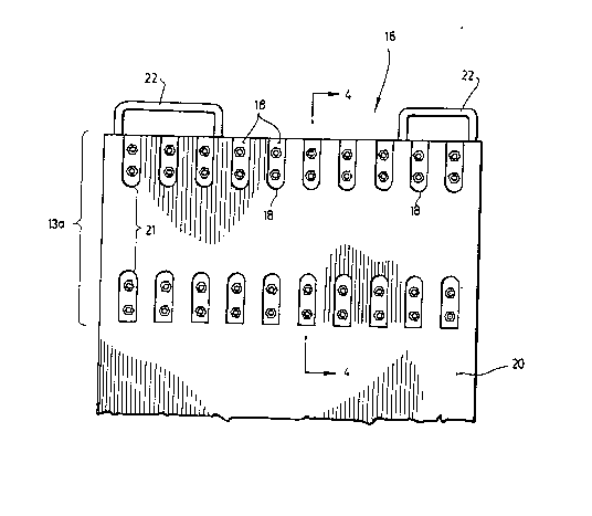
Figure 1 is a top plan view of the modular rail sections of
the invention when assembled to form two parallel rails;
Figure 2 is a bottom plan view of a portion of the load-
carrying plate according to the invention;
Figure 3 is a cross section view of one rail section of
Figure 1 as cut along line 3-3;
Figure 4 is a cross section view of the plate of Figure 2 as
cut along line 4-4: and
Figure 5 is an elevational view of the device of the
invention, when a hydraulic jack is retained between the
supporting elements of the rail sections according to the

-- 2061864
invention.
DRT~TJ~ D~SCRIPTIQN OF ON~ EXA~P~ OF ~ PR~F8RR~D
ENBODIMENT
Figure 1 shows a partial assembly of modular rail sections
10, having a length much larger than its width, and a width
much larger than its thickness. These sections 10 can be
assembled one end adjacent to another section's end to form
a rail of variable length depending on the number of
sections positioned one after the other. These modular
sections 10 are adapted to be positioned on top of
conventional rails or to be assembled on top of a series of
transversal dormants. These modular sections 10 when
assembled one after the other are to be positioned in two
parallel longitudinal rails 15a and 15b. These sections 10
have an upper surface 12 from which upwardly projects a row,
preferably a central row, of supporting elements 14
positioned at regular intervals along the length of the
rail. Each supporting element comprises a middle layer 28,
and an upper layer 30.
Figure 2 shows a portion of a load carrying plate 16 that is
sized to extend transversally between the rails 15a and 15b.
The plate 16 has an undersurface 20 having two opposite edge
portions 13a and (13b not shown) overlying the rails 15a and
15b (not shown) respectively. The plate 16 is movable along
these rails and each opposite edge portion 13a (or 13b) is
guided therealong by two parallel rows of guiding elements
18 that project down from the undersurface 20, each guiding
element 18 being positioned at regular intervals. The
guiding elements 18 are positioned and sized so as to define

- 2~61864
in between them a guiding channel 21.
Both the rail sections 10 and the load carrying plate 16
comprise handles 24 and ~2 respectively for helping users to
add or remove them from this assembly.
As shown in Figure 3, the supporting elements 14 of the
modular rail section 10 comprise a middle layer 28 and an
upper layer 30 that projects upwardly from the upper surface
12 of the section 10. The middle layer 28 and upper layer 30
are in the form of pads, and the upper pad 30 is made of a
friction material, preferably of low friction material such
as very high molecular weight plastic, or of a high friction
material such as steel. These pads 28 and 30 are eecured
with screws 32 that may be untightened to separate the pads
30 from the middle layer 28 to allow user to replace the
upper layer 30 after it is worn or to ~hange for another
friction material.
Figure 4 shows the load carrying plate 16 with its rows of
guiding elements 18 projecting downwardly from the
undersurface 20, the space between each row defining the
guiding channel 21. The two rows of supporting elements 14
releasably engage in the guiding channel 21 when the plate
16 is positioned on top of the rail 15a. The guiding
elements 18 comprise a middle layer 36 of steel, and a
bottom layer 38 that is made out of a friction material,
preferably low friction material such as very high molecular
weight plastic or high friction material such as steel. The
middle layer 36 and bottom layer 3B are in the form of pads
secured to the body 34 of the plate by screws 40 that may be
untightened to separate the pads 36 and 38 and allow a user

- 2061864
to replace the bottom layer 38 after it is worn or to change
the friction material.
As may also be seen from Figures 3 and 4, once the carrying
plate 16 is positioned on top of the rail 15a, the only
surfaces that will come in contact with each other are the
undersurface ~0 of the carrying plate 16 with the upper
layer 30 of the supporting elements 14 of the rail 15a, and
the upper surface 12 of the rail 15a with the bottom layer
38 of the guiding elements 18 of the carrying plate 16.
Of course, to attain this, the abutting elements 14 must be
of the same height as the guiding elements 18. Also, it is
to be understood that the abutting elements 14 may be
positioned in two parallel rows, whereas the guiding
elements 18 may be positioned in one central row to attain
the same effect.
This system allows a user to reduce the friction during the
sliding of the carrying plate 16 since no two steel surfaces
touch each other. Moreover, since the upper layer 30 and
bottom layer 38 are easily replaceable, it does not
constitute a problem if the high molecular weight plastic
wears out since these modular supporting elements 14 and
guiding elements 18 may easily be replaced.
Again, this system permits the removal of low friction
material and replacement by upper and bottom pads made out
of steel (a higher friction material) allowing the user to
control the friction of the two surfaces sliding against
each other.

2061864
Finally, as shown in Figure 5, this system is made in such
a fashion so that the supporting elements 14 of the rail
sections may serve as retaining means for the hydraulic jack
42 that incrementally pushes the heavy load. This jack 42
comprises a plurality of feet 44 sized so that they may be
positioned snugly between two abutting elements 14 and
therefore secure the hydraulic jack 42 in fixed position
when it is used to push the load.

Dessin représentatif
Une figure unique qui représente un dessin illustrant l'invention.
États administratifs

2024-08-01 : Dans le cadre de la transition vers les Brevets de nouvelle génération (BNG), la base de données sur les brevets canadiens (BDBC) contient désormais un Historique d'événement plus détaillé, qui reproduit le Journal des événements de notre nouvelle solution interne.

Veuillez noter que les événements débutant par « Inactive : » se réfèrent à des événements qui ne sont plus utilisés dans notre nouvelle solution interne.

Pour une meilleure compréhension de l'état de la demande ou brevet qui figure sur cette page, la rubrique Mise en garde , et les descriptions de Brevet , Historique d'événement , Taxes périodiques et Historique des paiements devraient être consultées.

Historique d'événement

Description Date
Le délai pour l'annulation est expiré 2009-02-26
Lettre envoyée 2008-02-26
Inactive : CIB de MCD 2006-03-11
Lettre envoyée 2000-02-03
Lettre envoyée 1999-12-23
Accordé par délivrance 1996-08-27
Demande publiée (accessible au public) 1993-08-27
Toutes les exigences pour l'examen - jugée conforme 1992-02-26
Exigences pour une requête d'examen - jugée conforme 1992-02-26

Historique d'abandonnement

Il n'y a pas d'historique d'abandonnement

Historique des taxes

Type de taxes Anniversaire Échéance Date payée
TM (brevet, 6e anniv.) - petite 1998-02-26 1998-02-11
TM (brevet, 7e anniv.) - petite 1999-02-26 1999-02-15
Enregistrement d'un document 1999-08-23
TM (brevet, 8e anniv.) - petite 2000-02-28 2000-02-14
TM (brevet, 9e anniv.) - petite 2001-02-26 2001-01-31
TM (brevet, 10e anniv.) - petite 2002-02-26 2001-12-07
TM (brevet, 11e anniv.) - petite 2003-02-26 2003-01-24
TM (brevet, 12e anniv.) - petite 2004-02-26 2004-01-05
TM (brevet, 13e anniv.) - petite 2005-02-28 2005-02-08
TM (brevet, 14e anniv.) - petite 2006-02-27 2006-01-17
TM (brevet, 15e anniv.) - petite 2007-02-26 2007-02-19
Titulaires au dossier

Les titulaires actuels et antérieures au dossier sont affichés en ordre alphabétique.

Titulaires actuels au dossier
2866-0322 QUEBEC INC.
Titulaires antérieures au dossier
MICHEL LUSSIER
Les propriétaires antérieurs qui ne figurent pas dans la liste des « Propriétaires au dossier » apparaîtront dans d'autres documents au dossier.
Documents

Pour visionner les fichiers sélectionnés, entrer le code reCAPTCHA :


Pour visualiser une image, cliquer sur un lien dans la colonne description du document. Pour télécharger l'image (les images), cliquer l'une ou plusieurs cases à cocher dans la première colonne et ensuite cliquer sur le bouton "Télécharger sélection en format PDF (archive Zip)" ou le bouton "Télécharger sélection (en un fichier PDF fusionné)".

Liste des documents de brevet publiés et non publiés sur la BDBC .

Si vous avez des difficultés à accéder au contenu, veuillez communiquer avec le Centre de services à la clientèle au 1-866-997-1936, ou envoyer un courriel au Centre de service à la clientèle de l'OPIC.


Description du
Document 
Date
(aaaa-mm-jj) 
Nombre de pages   Taille de l'image (Ko) 
Abrégé 1993-12-04 1 33
Description 1993-12-04 7 242
Page couverture 1993-12-04 1 14
Dessins 1993-12-04 4 66
Revendications 1993-12-04 2 72
Revendications 1996-08-27 2 78
Description 1996-08-27 7 257
Abrégé 1996-08-27 1 35
Page couverture 1996-08-27 1 12
Dessins 1996-08-27 4 60
Dessin représentatif 1999-02-18 1 16
Courtoisie - Certificat d'enregistrement (document(s) connexe(s)) 1999-12-23 1 115
Courtoisie - Certificat d'enregistrement (document(s) connexe(s)) 2000-02-03 1 115
Avis concernant la taxe de maintien 2008-04-08 1 172
Taxes 2003-01-24 1 30
Taxes 2004-01-05 1 30
Taxes 1999-02-15 1 34
Taxes 2001-12-07 1 31
Taxes 1998-02-11 1 42
Taxes 2000-02-14 1 30
Taxes 2001-01-31 1 32
Taxes 2005-02-08 1 27
Taxes 2006-01-17 1 31
Correspondance 2007-01-10 3 105
Taxes 2007-02-19 1 43
Taxes 1996-01-22 1 44
Taxes 1997-01-31 1 41
Taxes 1995-02-08 1 48
Taxes 1994-01-12 1 36
Correspondance reliée au PCT 1999-10-22 1 40
Correspondance reliée au PCT 1999-08-23 2 58
Correspondance reliée au PCT 1996-06-18 1 33
Courtoisie - Lettre du bureau 1999-08-24 1 22