Note: Descriptions are shown in the official language in which they were submitted.
RCA 9'6';
1 CATHODE-RAY TUBE HAVING A SHRINICFIT IMPLOSION
PRQTECTION BAND WITH TENSION LIMITING MEANS
This invention relates generally to cathode-ray
tubes (CRT's) having implosion protection bands and,
more particularly, to such tubes having shrinkfit
implosion protection bands with tension limiting means
formed therein.
A cathode-ray tube is evacuated to a very low
internal pressure and accordingly is subject to the
possibility of implosion due to the stresses produced by
atmospheric pressure acting on all surfaces of the
tube. This problem has been addressed in the art by
providing the CRT with an implosion protection band.
Such a band is used to apply a compressive force to the
sidewall of a faceplate panel of the CRT to redistribute
some of the forces. The redistribution of the forces
decreases the probability of an implosion of the tube; by
minimizing tension in the corners of the panel. An
implosion protection band is also beneficial because it
improves the impact resistance of the tube. Glass in
compression is stronger than glass which is in tension,
and the band causes compression in panel areas which
otherwise would be in tension. Additionally, in the
event of an implosion, the redistributed stresses cause
the imploding glass to be directed toward the back of
the cabinet in which the tube is mounted, thereby
substantially reducing the probability of someone in the
vicinity of the imploding tube being injured.
An implosion protection band of the shrinkfit
type typically is manufactured by forming a strip of
steel into a loop having the same configuration as the
facepiate panel to be protected, and joining the two ends
of the strip on one side of the band. In some
instances, the band is made by joining two identical
- 1 -
~o~~~g~
RCA 86,329
1 strips,on two sides,to form the loop. For both types of
bands, the periphery of the loop is slightly smaller
than the periphery of the faceplate panel. The loop is
heated to approximately 300° to 500°C,and the
coefficient of expansion of the material causes the loop
to expand to dimensions permitting the loop to be
slipped around the sides of the faceplate panel. As the
band coels,it shrinks and tightly surrounds the panel,
thereby applying the necessary implosion protection
compression to the face late
p panel. The compressive
force can be accurately controlled by exceeding the
yield point of the metal in the band.
The ends of the strips are permanently joined by
either welding or crimping. In either event, because
the strip is used to apply substantial pressure to the
sidewall of the tube, it is essential that the
connective joint, formed where the two ends are coupled
together, be sufficiently strong to withstand the
tension applied to it by the band. Typically, the
connective joint is designed to withstand a minimum
tension of 5000 pounds (2268 kg). Because the tension
of the band is directly proportional to the yield strength
of the material and its sectional area, any increase in
the yield strength of the band material that is in
excess of its maximum limit will exert a tension on the
connective joint in excess of its minimum design limit
and may cause the joint to fail.
A cathode-ray tube according to the present
invention comprises an evacuated envelope which includes a
faceplate panel joined to a funnel. A shrinkfit implosion
protection band of at least one strip of metal, having
oppositely disposed ends, is secured at a connective joint
to form a loop with cold dimensions sli_qhtly smaller than
the periphery of the panel prior to application of the
band. The band has a given sectional area with
2~519~~
RCA 86,329
1 at Ieast one opening formed therethrough. The band is
fitted around the periphery of the panel to apply a
compressive force thereto, as a result of the tension of
the band. The band is improved by providing means,
within the band and in communication with the opening,
for lowering the tension of the band below the minimum
design limit of the connective joint.
In the drawings:
Fig. 1 is a perspective view of a CRT with a
novel shrinkfit implosion protection band according to
the present invention.
Fig. 2 is a front view of the tube and band of
Fig. 1.
Fig. 3 is a typical elongation curve for a
material from which the band can be made.
Fig. 4 is an enlarged view of a segment of the
novel band, showing an opening and slot with a degaussing
coil-retaining clip disposed within the opening.
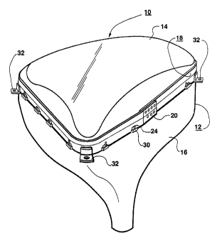
With respect to Figs. 1 and 2, a CRT 10 comprises
an evacuated envelope 12 having a faceplate panel 14
joined by a frit seal, not shown, to a funnel 16. An
electron gun, also not shown, closes the opposite end of
the funnel.
A shrinkfit implosion prevention band 18, in the
form of a loop with cold dimensions slightly smaller
than the periphery of the panel 14, is fitted around the
panel by heating the band within the range of 300° to
500oC,to cause it to expand, and then allowing it to
cool. The tension of the cooled band 18 applies a
compressive force to the panel. The band 18 is formed
by joining together the opposite ends of at least one
steel strip to form a connective joint 20. In the
present embodiment, the strip has an overall unfolded
width of about 3.0 inches (76.2mm) and a thickness
- 3 -
RCA 86,329
1 within the range of 0.042 to 0.045 inch (1.07 to
1.14mm). An inch (25.4mm) of one edge 22 of the strip
is folded over, to provide a double thickness of material
on the faceplate-side of the band and to create a band
18 with an operable width, W, of about 2 inches
(50.8mm). A plurality of openings 24 are formed by,
e.g., lancing the band 18 adjacent to the opposite
unfolded edge 26. Each of the openings 24 has a base 28
spaced a distance, D, of about 0.375 inch (9.5mm),
groin the edge 26. A narrow strip of the band material
bridges the opening 24. The strip is formed out of the .
plane of the band l8,to define a clip-receiving retainer
30. Typically, the retainer 30 has a width, wl, of
about 0.184 inch (4.67mm) and an effective length, L,
of about 0.78 inch (19.81mm), which is slightly less
than the length of the bass 28. A mounting lug 32 is
attached to the band 28 at each of the corners. As
described thus far, the band 18 is conventional.
A problem with the conventional band 18 is that
variations in the yield strength or the thickness of the
material, above the maximum allowable values, could
result in a tension on the connective joint 20 in excess
of its minimum design limit of 5000 pounds, resulting in
a failure of the joint. The minimum design limit is the
minimum tension at which the joint 20 will fail. The
steel band material has a specified yield strength, Y,
in the range of 37,000 to 42,000 psi (26.0 to 29.5 kg/mm2).
The maximum thickness, t, of the material is 0.045 inch
(1.14mm). The effective width W'of the band is defined
as the overall width, 3.00 inches (76.2mm), less the depth
of the opening 24, 0.375 inch (9.5mm), or 2.625 inches
(66.7mm). The maximum tension on the joint 20, for material
having a yield strength of 42,000 psi (29.5 kg/mm2), is
Tmax ° Y x W'x t
Tmax = 42,000 psi x 2.625 in x 0.045 in
(29.5 kg/mm2 x 66.7mm x 1.14mm)
Tmax - 4961.25 pounds (2243 kg).
- 4 -
2~61J~~
RCA 86,329
1 The tension on the joint 20 is below the minimum design
limit, and the joint will hold. However, tests have shown
that, after forming and working, the steel strip has a
yield strength as high as 47,000 psi (33.0 kg/mm2). The
resulting tension on the joint 20 for this material is
T1 = 47,000 psi x 2.625 in x 0.045 in
(33.0 kg/mm2 x 66.7mm x 1.14mm)
T1 = 5551.88 pounds (2509 kg).
This latter value of tension may cause the joint 20 to
fail .
To prevent failure of the joint 20, while still
providing sufficient compressive force on the panel 18,
the two openings 24 adjacent to each of the lugs 32 at
the corners of the band 18 are modified to include a
Slot 34 which communicates with the openings 24. Each
of the slots 34 has a slot base 36 with a length, 1, of
about 0.25 inch (6.35mm), and a depth, d, of about 0.30 inch
(7.62mm). The depth, d, of the slot 34, in combination with
the depth, D, of the opening 24, increases the effective
overall depth to about 0.675 inch (l7.lmm), thereby
reducing the effective folded band width to 2.325 in (59.1mm).
The resulting force on the joint 20, for steel strip having
a thickness of 0.45 inch (1.14mm) and a maximum yield
strength of 47,000 psi (33.0 kg/mm2), is then
T2 = 47,000 psi x 2.325 in x 0.045 in
(33.0 kg/mm2 x 59.1mm x 1.14mm)
T2 = 4917.38 pounds (2223 kg).
Thus, even in the worst case situation of a
maximum material thickness of 0.045 inch (1.14mm) and a
yield strength of 47,000 psi (33.0 kg/mm2), the tension on
the joint 20 will not exceed the minimum design limit of
5000 pounds (2268 kg).
Prior to fitting the band 18 on the tube 10, the
band is stretched to slightly exceed the elastic limit
of the metal, thereby causin the band to
g yield and to
apply a known, predictable tension on the tube. This is
evident from Fig. 3, which shows that the tension remains
substantially constant after approximately a 5$ elongation.
The band 18 is stretched by the method described in
- 5 -
RCA 86,3~~~~~~~
1 Canadian patent application No.2029538-4 , filed on
November 08, 1990.
A segment of the novel band 18 is shown in Fig.
4. A clip 38 is disposed within the opening 24 in the
band 18. The clip 38 engages the clip-receiving
retainer 30 and accurately locates a degaussing coil 40
relative to the tube, not shown. The slot 34 does not
interfere with either the location or retention of the
clip 38. ~y incorporating the slot 34 and the opening
24 in each of the eight corner-adjacent positions,
economy is achieved by forming both the opening and the
slot in a single operation. Additionally, since the
tension on the band 18 is greater near the corners than
elsewhere, the greatest protection for the joint 20 is
achieved by locating the slots 34 within the eight
corner-adjacent openings 24, so that the tension is
substantially uniformly distributed to each of the four
corners of the band.
25
35
- 6 -