Note: Descriptions are shown in the official language in which they were submitted.
2Q~20~6
~~~~TR~1~L~..~.~T~
FIF~I,13 491F Th~I; IN~~~N
S This invention relates to a device For controlling the tempt:rature of a
predetermined
area, and more particularly, to an electronic thermostat which can be
intuitively operated '
to control the temperature in a predetermined area and to a method of ef
ficicntly
controlling the temperature utilizing the electronic thermostat.
IiACK("~R~UNID ~I: TgIE I,~dyli NTIOIe],
A thermostat can be used, as part of a temperature controll system, to control
heating
units and air conditioning units. The electronic thermostat of the present
invention
accommodates heating units and air conditioning units in order to maintain
comfort and
economy levels of a predetermined area.
Known electronic thermostats have a day set temperature For heating, ~, 70
degrees
Fahrenheit; a night set back temperature for heating, c.Q.. 62 degrees
Fahrenheit, an actual
time readout, a time for set back to start, a time for set back to end, and
overrides to raise '
or lower temperature as desired.
Known electronic thermostats also have a day set temperature for cooling, e.aa
72
degrees Fahrenheit, and a night set back temperature for cooling, ~", 76
degrees
Fahrenheit. A switch, which controls the operation of a fan, shay be set on
"ON" for
IS continuous operation or an "AUTO" for automatic (cyclical) operation.
Further, the
thermostat has a "OFF"/"HEAT"/"COOL"/"AUTO" switch {system state switch).
For heating, the system state switch is set to "HEAT." For cooling, the system
state
switch is set to "COOL:'
Sometimes, such as in the spring or fall seasons, one may desire to control
both the
air conditioner and furnace with the thermostat due to the wide range of
outside
temperatures that may occur during these times. This can be done by setting
the system
state switch to "AUTO." In this state, tha thermostat can turn on the air
conditioner on
a hot spring day and then turn on the furnace that night as it gets cooler.
This enables
the operator to keep an area within a desired range of temperatures. The
present invention
functions similarly. A thermostat is a devise which is capable of keeping a
predetermined
area within a range of preselected temperatures when the device is coupled to
both an air
conditioning unit and a h~;ating unit. The electronic thermostat controls the
state (i,~,; on
or off) of both the air conditioning unit and the heating unit in order to
keep a
-2-
predetermined area within a range of preselected temperatures. Essentially, if
the
temperature is greater than the maximum preselected temperature: one desires,
the electronic
thermostat turns an the air conditioning unit. On the other hand, if the
temperature is less
than the minimum preselected temperature one desires, the electronic
thermostat turns on
the heating unit.
Currently, thermostats are provided which require programming for a variety of
operating modes. Programming is often difficult, especially far the elderly
who are less
apt to be familiar with electronic gadgetry. For instance, a programming error
can result
by attempting to set the maximum desireable temperature lower than the'
minimum
IO desireable temperature. if this programming error were allowed to go
undetected, the
electronic thermostat would seek to turn on both the heating unit and the air
conditioning
unit, wasting a great amount of energy. Previous electronic thermostats deal
with this
programming error by taking this possible error into account in their
software, hardware
and/or "firmware." However, even if the electronic thermostat executes a
program which
prevents turning on both the air conditioning arid heating units, in addition
to warning the
. operator of the error, the operator is still forced to reprogram the
electronic thermostat,
wasting valuable time. Further, until the operator recognizes the warning, the
predetermined area may not be heated or cooled, resulting in discomfort or
even damage
to the predetermined area if the operator is not present. Therefore, it is
much more
desireable to have an electronic thermostat which is impossible to incorrectly
program.
Prior to the present invention, electronic thermostats also required
maintenance in
the form of periodically checking and/or replacing batteries to ensure the
electronic
thermostat will function in the event of a power failure. However, the present
invention
requires no periodic maintenance because a super capacitor Is used to retain
the memory
2S of the electronic thermostat in the event of a temporary power failure.
Also, known
electronic thermostats require the operator to remember to check and/or
replace a Filter,
increasing the efficiency of air flow and energy use. However, the present
invention
flashes the words "CHECK F1LTER" once a fan has accumulated a predetermined
running
-3-
time, for example 360 hours or more of running time. ~"urther, known
electronic
thermostats could not display the local (outdoor) temperature and the high and
tow local
temperatures of the day. Lastly, known electronic thermostats do not contain
diagnostic
information for the furnace and compressors within the unit itself.
Accordingly, it is an object of the present invention to provide an electronic
thermostat which can be programmed simply and intuitively by almost any user.
Another object of the present invention is to provide an electronic thermostat
which is
"user friendly" to the operator, especially elderly operatars (~, the group of
people who
are home most often and need to adjust their thermostats most frequently).
Still another object of the present invention is to provide notification to
the operator
to check for a dirty filter when the fan has accumulated a predetermined
running time.
A further object of the present invention is to provide a structure For
providing the
current outside temperature, and the high and low temperature of the day.
Yet a further object of the present invention is to provide a structure and a
method
for easily displaying diagnostic information on a temperature control system.
Yet another object of the present invention is to provide an
electronic~thermostat
capable of storing preselected temperatures, in addition to other information,
in its memory
in the event of a power failure for a preselected period of time, without
requiring periodic
maintenance.
A further object of the present invention is to provide an electronic
thermostat
capable of simultaneously displaying the maximum and minimum temperatures for
both the
first and second time intervals, in addition to other information, with the
simple touch of
a button.
Still another object of the present invention is to provide an electronic
thermostat
which includes intuitively operated slides for setting control temperatures
for both day and
night set back operation.
Another object of the present invention is to provide an electronic thermostat
with
a digital readout enlarged in a scale that eliminates the need for "back
lighting" the
-4-
2U~~U"~~
display, which is commonly done on known electronic thermostats with smaller
displays to
facilitate their viewing in dimly lit areas, for example hallways.
Another object of the present invention is to provide a simple means to change
from
day to night operation by pressing a button having an integral LSD that glows
during night
operation, whereby the glowing LI;D makes it easy to locate this button and
effect the
change in dimly lit areas, for example hallways.
Another object of the present invention is to provide an electronic thermostat
with
a digital readout coordinated with slide controls for easily setting the
temperature operating
program for both day and night operation.
A further object of the present invention is to provide a thermostat cover
that can
be manipulated to display, in addition to other information, the settings of
the Cirst pair
of slide means, the second pair of slide means, the third pair of slide means,
and the
current temperature.
Yet another object of the present invention Is to provide a method far
intuitively
and simply controlling the temperature of a predetermined area via an
electronic
thermostat.
Other objects and advantages of this invention will become apparent
hereinafter.
_5_
~o~~~~~
JM>V ~1~, ~~'' ~'~lE; IIVVaaIdTIDIV
Predetermined areas, such as a house, a room in a house, an office, or an
entire
building, can have their temperature controlled as desired by correctly
programming an
electronic thermostat. The difficulty in programnaing conventional thermostats
can be
greatly diminished, if not entirely eliminated, by providing an c;lectronic
thermostat which
is both intuitive to program and user friendly.
According to a preferred farm of the invention, the electronic thermostat
functions
to keep the predetermined area at a temperature between a first maximum
temperature and
a first minimum temperature during the daytime, and a second maximum
temperature and
a second minimum temperature during the nighttime. In the daytime, or first
time interval,
a first pair of slide means can be used to set the first maximum temperature
and the first
minimum temperature. In the nighttime, or second time interval, a second pair
of slide
means can be used to set the second maximum temperature and the second minimum
temperature. A third pair of slide means can be used to set the beginning time
and the
ending time of the second time interval. Because there are only two time
intervats, this
third pair of slide means essentially sets the beginning time and the ending
time of the
first time 'interval also.
In the "AUT~" setting, during the first time interval the temperature of the
predetermined area is maintained between the first maximum temperature and the
first
minimum temperature. During the second time interval, the temperature of the
predetermined area is maintained between the second maximum temperature and
the second
minimum temperature. Override means arc available which enable the tempceature
of the
predetermined area to be maintained between the first maximum temperature and
the first
minimum temperature during the second time interval and between the second
maximum
temperature and the second minimum temperature during the first time interval
by merely
depressing an illuminated button. Thus, even if the operator wakes up during
the middle -
_6_
of the night and cannot go back to sleep, the illuminated button is easy to
find and enables
the operator, for instance, to have the predetermined area maintained in the
generally more
comfortable range between the first maximum temperature and first minimum
temperature
during his or her waking hours.
S Additionally, the present invention is easy to maintain and program in other
respects, A one farad super capacitor stores energy which is capable of
maintaining the
current time, the number of hours of operation of the unit, and the maximum
and
minimum iemperaturc of the day, in addition to other information, in the event
of a power
loss. Even though the display of the electronic thermostat goes biank, the
super capacitor
enables the electronic thermostat to store this information in memory for up
to 24 hours.
If power is restored prior to 24 hours elapsing, there is no aced to reprogram
the electronic
thermostat. Additionally, because a super capacitor is used (as opposed to
other electronic
thermostats which use batteries to store information in the event of a power
failure), the
operator need not periodically check the electronic thermostat to see if the
batteries are
still operable. Additionally, the present invention allows the operator to
review all
minimum temperatures, all maximum temperatures, and the beginning and ending
times of
the second time interval by simply depressing a thermostat coves. '
The present invention offers a number of advantages over prior electronic
thermostats. First, the electronic thermostat of the present invention greatly
diminishes,
if not totally eliminates, the chance of a programming error. Second, the
present invention
is intuitive to program and user friendly. Third, the present invention is
essentially
maintenance fees as it does not require checking and/or replacing batteries.
Fourth, the
present invention allows one to display the current local (outdoor)
temperature in addition
to the high and tow outdoor temperatures of the day. Lastly, diagnostic
information on
components of the heating and cooling systems can be displayed on a display
moans of the
electronic thermostat. By using the present electronic thermostat, the
temperature of a
predetermined area can be efficiently controlled with ease unattainable by the
prior art.
CA 02062076 1999-06-30
Thus, according to a first broad aspect the invention
provides an electronic thermostat for controlling the temperature
of a predetermined area comprising: a first pair of slide means for
controlling the temperature of the predetermined area during a
first time interval; a second pair of slide means for controlling
the temperature of the predetermined area during a second time
interval; and a third pair of slide means for controlling a
beginning time and an ending time of the second time interval
whereby the first time interval and the second time interval
consist essentially of a 24 hour period and the temperature of the
predetermined area is determined by the position of the first pair
of slide means during the first time interval and the temperature
of the predetermined area is determined by the position of the
second pair of slide means during the second time interval.
According to a second broad aspect the invention provides
an electronic thermostat for controlling the temperature of a
predetermined area comprising: a housing means, the housing means
comprises a thermostat and a subbase; the subbase further comprises
a subbase board, a first means for electrical communication, and a
first means for mechanical coupling; the thermostat further
comprises a control panel, a main thermostat board, a thermostat
cover, a second means for electrical communication, and a second
7a
CA 02062076 1999-06-30
means for mechanical coupling, the second means for electrical
communication being electrically connected to the first means for
electrical communication and the second means for mechanical
coupling being connected to the first means for mechanical
coupling; the control panel further comprises a first pair of slide
means arranged in an essentially linear manner, a second pair of
slide means arranged in an essentially linear manner, and a third
pair of slide means arranged in an essentially linear manner, the
first pair of slide means further comprises a cool slide means and
a heat slide means, both of which are electronically connected to
the main thermostat board, the second pair of slide means further
comprises a cool slide means and a heat slide means, both of which
are electronically connected to the main thermostat board, and the
third pair of slide means further comprises a begin slide and an
end slide, both of which are electronically connected to the main
thermostat board, whereby the third pair of slide means can be
moved to set a second time interval in which the position of the
second pair of slide means controls the temperature of the
predetermined area, the third pair of slide means also essentially
defining a first time interval as the time of day which is not
occupied by the second time interval, in which the position of the
7b
CA 02062076 1999-06-30
first pair of slide means controls the temperature of the
predetermined area.
According to a third broad aspect the invention provides
a method of controlling the temperature of a predetermined area via
an electronic thermostat comprising the steps of: sliding a first
pair of slide means for controlling the temperature of the
predetermined area during a first time interval; sliding a second
pair of slide means for controlling the temperature of the
predetermined area during a second time interval; and sliding a
third pair of slide means for controlling a beginning time and an
ending time of the second time interval.
7c
2~~2~'~~
aiaaaai~~ ~~.s~atarTa~i ~1~ Ta~~aaaa~,waN~s
These and other objects, advantages and features of the invention will
hereafter
appear for purposes of illustration, but not of limitation, in connection with
the
accompanying drawings in which like numbers refer to like parts through~ut and
in which:
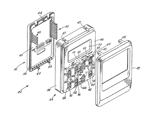
Figure 1 is a schematic block diagram of a temperature control system;
Figure 2 is a perspective view of a preferred form of an electronic thermostat
made
in accordance with the present invention;
Figure 3 is an exploded perspective view showing a more detailed preferred
form
of the electronic thcrmastat made in accordance with the present invention;
Figure 4 is a perspective rear view of the thermostat portior4 of an
electronic
thermostat made in accordance with the present invention;
Figure 5 is a schematic block diagram of a subbase printed circuit board of
the
electronic thermostat made in accordance with the present invention;
Figure 6 is a schematic block diagram of a main thermostat board of the
electronic
thermostat made in accordance with the present invention; and
Figure 7 is a schematic diagram of a local temperature sensor of the main
thermostat
board made in accordance with the present invention.
_g_
DE I,ED DE It P F T E IDREF E E R D IvIE
Referring to Figure 1, the temperature of a predetermined area 10 to be
conditioned
S is maintained by forcing warm air or cold air into it via duct 12 and
heating unit I4 or
duct 12 and air conditioning unit 16, respectively. As illustrated, the
heating unit 14 may
be, for example, a conventional gas fired, oil fired or electric furnace. The
air
conditioning unit 16 includes a refrigeration system comprising an evaporator
coil 1I,
which sits in the duct 12 above the heating unit 14, a typical compressor 13,
condenser coil
15, and expansion means 17. The heating unit 14 and air conditioning unit 16
arc
responsive to clcctrical control lines 18 and 20, rcspcctivcty, which emanate
from the
electronic thermostat 22. lVhen the temperature of the predetermined area 10
is less than
the minimum temperature desired, the electronic thermostat 22 sends a signal
to the heating
unit 14 via electrical control line 18, turning on the heating unit 14 and
forcing warm air
through duct 12 into the predetermined area 10 until the desired minimum
temperature is
' attained. If the predetermined area 10 is at a higher temperature than the
maximum
temperature desired, electronic thermostat 22 sends a signal to air
conditioning unit l( via
electrical control Line 20 which forces cool air into the predetermined area
10 via duct 12
until the desired maximum temperature is attained.
The heading unit 14, or furnace, includes a Can 24, heat exchanger 26 with
burners
28 and the normal controls. The furnace 14 is connected to the predetermined
arcs 10 by
two ducts, a duct 12 for supplying air to the predetermined area 10 and a
return duct 32
for returning air from the predetermined area 10.
Referring to Figures 2 through 4, the electronic thermostat 22 is comprised of
a
thermostat 34 and a subbase 3b, both of which are contained in a housing means
38. The
subbase 36 is further comprised of a subbase printed circuit board 40, a first
means 42 for
clecteical communication, and a first means 44 for mechanical coupling, all
connected as
shown. The subbase 36 also has a plurality of guides 37 to facilitate
installation of the
_g_
thermostat 34 onto the subbase 36. The thermostat 34 further comprises a
control panel 46,
a main thermostat board 48 (fig Fig. 4), a thermostat cover 49, a second moans
50 far
electrical communication (~~g, Fig. 4), and a second means 52 for mechanical
coupling (egg
Fig. 4) all interconnected as shown in Fig. 2 through Fig. 4. The first means
42 and the
second means 50 preferably comprise complementary intererrgaging male and
female
members. The thermostat cover 49 has two grooved prongs 45 which, in
conjunction with
the tyvo grooved prong acceptors 47 of the housing means 38, serve to
rotatably attach the
thermostat cover 49 to the housing means 38.
Referring to Fig. 2, the control panel 46 is further comprised of a first pair
of slide
means 54, a second pair of slide means 60, a third pair of slide means 66, an
override
means 68, and a display means 70 (preferably an LCD model 4878-313-433
manufactured
by Hamlin), all arranged as shown. The control panel is also comprised of a
fan switch
71 which places the fan 24 (egg Fig. 1) in an "Oht" state or an "'AUTO" state.
Simply by
viewing the labeled control panel 46, the electronic thermostat 22 can be
programmed by
using one's intuition. However, an explanation is provided.
One can deduce that a 24 hour day or period Is broken down into two smaller
periods, a day period (or first time interval) and a night period (or second
tim~c interval).
Once the night period is determined, the day period automatically becomes the
remainder
of the 24 hour period. The third pair of slide means 66 determines the
beginning time and
ending time of the night period. The third pair of slide means 66 is comprised
of a first
slide 72, an second slide 74, a third path 76 having a first end 78 and a
second end 80, the
first slide 72 being closer than the second slide 74 to the first end 78 of
the third path 76
at all times. Simply sliding the first slide 72 towards the first end 78 or
towards the
second end 80 adjusts the beginning time of the night period to an earlier or
later setting,
respectively. Likewise, simply sliding the second slide 74 towards the first
end 78 or
towards the second end 80 adjusts the ending time of the night period to an
earlier or later
setting, respectively. Also, as the beginning time and ending time are
adjusted, the I.GD
_10_
70 tracks and displays the changing time in increments of fifteen minutes in
order to alert .
the operator that the desired beginning and ending times have been reached.
After differentiating between the night period and the day peeiod, the
operator sets
the first maximum temperature and first minimum temperature via the first pair
of slide
means 54. Then, the operator sets the second maximum temperature and the
second
minimum temperature via the second pair of slide means 60. Although normally
the first
pair of slide means 54 will control the temperature during the day period and
the second
pair of slide means will control the temperature during the night period,
these functions
can be reversed simply by depressing the override means 68 (~" the CANCEL
button). The
electronic thermostat 22 will resume normal operation by depressing the
override means 68
a second time. In other words, toggling the override means 68 changes the pair
oC slide
means that is currently controlling the temperature of the predetermined area
10. The
override means is illuminated by and LED 64 integral to the override means 68
only when
khe temperature is being controlled by the second pair of slide means (e.Q..
it is either the
night time or the override means was depressed so that the night time settings
are used to
control the temperature during the day). The "SYSTEM" button 82 is illuminated
by an
integral LEIJ 83 if the air conditioning unit 16 or the furnace 14 is In
operation.
The first pair of slide means 54 is further comprised of a first slide 84, a
second
slide 86, and a first path 88 having a first end 90 and a second end 92, the
first slide 84
being etoser than the second slide 86 to the first end 90 of the first path 88
at all times.
Simply sliding the first slide 84 towards the first end 90 or towards the
second end 92
raises or lowers, respectively, the first maximum temperature. Likewise,
sliding the second
slide 86 towards the fiCSt end 90 or towards the second end 92 raises ,or
lowers,
respectively, the first minimum temperature.
The second pair of slide means 60 is further comprised of a first slide 94, a
second
slide 96, and a second path 98 having a first end 100 and a second end 102,
the first slide
94 being closer than the second slide 96 to the first end 100 of the second
path 98 at ali
times. Simply sliding the first slide 94 towards the first end 100 or towards
the second end
11 _
102 raises or lowers, respectively, the second maximum temperature. Likewise,
sliding the
second slide 9S towards the first end 100 or towards the second end 102 raises
or lowers,
respectively, the second minimum temperature. An instantaneous readout is
displayed on
a display means 70 in response to sliding slides 84, 86, 94, 9b, 72 and 74.
The operator can
set the temperatures for the air conditioning unit. The first slide 84 can be
actuated to
set a day control temperature, e.u.. 70 degrees Fahrenheit, for the air
conditioning unit.
Another first slide 94 can be actuated to set a night control temperature,
e.a.. 74 degrees
Fahrenheit, for the air conditioning unit. Next, the operator can sot the
temperatures for
the furnace (heating unit). The second slide 86 can be actuated to set a day
control
temperature, c.a.. 68 degrees Fahrenheit, for the heating unit. Another second
slide 96 can
be actuated to set a night controt temperature, e.~.. 62 degrees Fahrenheit,
for the heating
unit. Finally, the operator can set the start and stop times for the night
period. A first
slide 72 sets the beginning time for the night period, ~,g", midnight, A
second slide 74 sets
the ending time for the night period, g~g,., 6:30 a.m. Basically, the operator
is reducing the
I S energy needed to heat or cool the predetermined area 10 by programming
desired
temperatures to be cooler at night in the winter and warmer at night in the
summer.
In the event of a power failure, the subbase printed circuit board 40 has a
super
capacitor 104 connected as shown in Fig. 5, preferably a 1.0 farted 5:5 volt
super capacitor
model number EEC-FSR5U105 manufactured by Panasonic, which supplies energy for
the
microcomputer's memory. The erdergy is supplied from the subbase printed
circuit board
40 to the main thermostat board 48 (~ Fig. 4) (and eventumlly to the
microcomputer on
the main thercraostat board 48 (fig Fig. 4)) via the first means 42 for
electrical
communication and the second means 50 For electrical communication (~, Fig.
4). The
super capacitor 104 stores energy sufficient to retain the current time, the
number of hours
of operation of the unit, and the maximum and minimum temperature of the day,
in
addition to other information, in the memory of the electronic thermostat for
24 hours.
It is not necessary to retain the first and second maximum temperatures, the
first and
second minimum temperatures or the beginning and ending time of the second
time interval
- 12-
as these are all maintained by their respective slide positions during an
extended power
outage. Thus, if there is a power failure for less than 24 houxs, the
electronic thermostat
22 does not require reprogramming. All that need be done is to reset the
current time.
Additionally, because the energy to operate the memory is stara;d in a super
capacitor 104
rather than a battery, it is not necessary to periodicalty ensure the storage
moans (either
super capacitor 104 or battery) is operable. Further, there is no need to
periodically replace
batteries.
'The display means 70 will flash the words "CHECK FILTER" with a fifty percent
duty cycle if the fan 24 (egg Fig, I) accumulates 360 hours of running time.
Thus, if the
fan is "on" fifty percent of the time, the "CkIECK FILTER" light will be
displayed every
thirty days. This visual indicator notifies the operator to check and/or
replace; the air
filter, which may increase both the quality of the air in the predetermined
area 10 and the
efficiency of the energy used to heat ar cool the predetermined area 10. If
the operator
depresses the thermostat cover 49 four times in rapid succession (less than
0.5 seconds
between depressions), then the electronic thermostat 22 will reset the
accumulated time of
the "CHECK FILTER" to acre hours and will turn off the flashing display. The
accumulated time cannot be inadvertently reset because the reset function is
not operational
if the "CHECK FILTER" prompt is not being displayed.
The display means 70 is responsive to the override means 6~ and a system state
slide
(the "OFF"/"HEAT"/"COOL"/"AUTO" switch) 69. The compressor 13 (~ Fig. 1) may
have
the capacity to serve two different settings (s.~.. a full Load and a half
load). This can be
accomplished, as is known to those of ordinary skill in the art, by utilizing
a two speed
compressor or two separate compressors. References to the "compressor"
hereinabove and
hereinafter refers to those compressors which can serve two differenk
settings. The
electronic thermostat 22 of the temperature control system (~ Fig. 1) provides
a method
of displaying information on a display means 70 of an electronic thermostat 22
regarding
remote parts (e.~.. both compressor l3 and heating unit 14 of Fig. I} of a
temperature
control system comprising the step of simultaneously manipulating an override
means 6g
. .. .,; , . . . ~ , . ~ .
20fifi~~fi
and a system state slide 69. The diagnostic information regarding remote parts
of the
temperature control system can be easily displayed on the display means by
simply: (1)
sliding the system state slide 69 to "OFF"; (2) holding the override means 68
continually
through step (6) in a depressed state; (3) sliding the system state slide 69
to the "MEAT"
position, displaying the number of hours the furnace has run in the upper left
and the
number of cycles of the Furnace in the lower left of the display means 70; (4)
sliding the
system state slide 69 to the "COOL" position, displaying the number of houa~s
the first
compressor has run in the upper left and the number of cycles of the first
compressor In
the lower left of the display means 70; (5) sliding the system state slide 69
to the "AUTO"
position, displaying the number of hours the second compressor has run in the
upper left
and the number of cycles of the second compressor in the lower left of the
display means
70; and (6) releasing the override means 68 and sliding the system state slide
69 to the
desired position, resuming normal operation of the display means 70 and
selecting the
desired function for the system.
IS As seen in Fig. 2, a thermostat cover 49 is mounted on electronic
thermostat 22.
/ When the thermostat cover 49 is depressed against a display button 108 for
one-half second
or more, the I,CD or display means 70 displays, in the following order, the
current
temperature set point, the maximum and minimum temperatures for both the first
and
second time intervals and the times at which the second time interval begins
and ends.
Next, normal display is resumed. The display button 108 delays operation one-
half second
before signaling the display means 70. Thus, inadvertently depressing the
thermostat cover
49 will not display all of the above information.
As shown in Fig. 3, slides 84, 86, 94, 96, 72, and 74 are uniquely
interconnected with
slidable switches 190, 188, 194, 192, 198, and 196, respectively. Further, the
system state
slide 69 and the fan switch 71 are uniquely interconnected to slidable
switches 202 and 200,
respectively. All slidablc switches 188, 190, 192, 194, 196, 198, 200, and 202
arc mounted
on the main thermostat board 48. Slidable switches 188 and 190 are disposed in
a generally
side by side relationship and are actuated by slide members 189 and 191,
respectively,
_ 14 _
2~~~~'~~
which comprise two of the six potentiometers 142 represented in Fig. b. This
arrangement
prevents setting the highest desirable temperature lower than the lowest
desirable
temperature during the f first time interval.
Similarly, slidablc switches 192 and 194 are disposed in a generally side by
side
S relationship and are actuated by a slide members 193 and 195, respectively,
which comprise
two of the six potentiometers 142 represented in Fig. 6. This arrangement
prevents setting
the highest desirable temperature lower than the lowest desirable temperature
during the
second time interval.
Similarly, slidable switches 196 and 198 ase disposed in a generally side by
side
relationship and are actuated by a slide members 197 and 199, respectively,
which comprise
two of the six potentiometers 142 represented in Fig. 6, This arrangement
prevents setting
the beginning time of the second time interval later Lhan the ending time of
the second
time interval,
Thus, in the configuration shown, raising a slide corresponds to raising
temperature
whereas lowering a slide corresponds to lowering temperature. ~Iso, as the
slides are raised
and lowered, the LCD 70 tracks and displays changing temperatures in
increments of one
degree Fahrenheit in order to alert the operator that the desired first
maximum
temperature, first minimum temperature, second maximum temperature or second
minimum
temperature has been reached.
A cover 43 of control pane! 46 is attached to the housing means 38 by a set of
prongs 206 on the cover 43 which cooperate with a set of apertures 208 an the
housing
means 38. Further, slidable switches 200 and 202 are actuated by slide members
201 and
203, respectively. Slide members 201 and 203 are connected to the fan switch
71 and the
system slide switch 69, respectively. The fan switch 71 is shown schematically
in Fig. S
as "fan switch 138."
Referring to Fig. 5, the subbase printed circuit board 40 is comprised of
super
capacitor 104, over temperature shut off switch 120, relays and switches 122,
124, 136 and
138, rectifier bridges 126, voltage regulators 128, 130, triac trigger 132,
and triac 134 ali
_ 15-
~Q~2~'~~
connected as shown. Preferably, voltage regulator 128 is comprised of a 9.0
volt voltage
regulator and voltage regulator 130 is comprised of S.0 volt and 4.4 volt
voltage regulators.
Turning to Fig. 6, the main thermostat board 48 is comprised of microcomputer
140,
potentiometers 142 (one for each of slides 84, 86, 94, 96, ?2, and 74 (~,r
Fig. 2)), local
S temperature sensor 144, A/D converter 146, A/D converter power switch 148,
low voltage
detector 150, power failure detector IS2, relay drivers IS4, relays 1S6 and
IS8, switches 160,
162 and 164, LED's 166, and 4.19 megahertz and 32.7 kilohertz timing crystals,
158 and 170,
respectively, connected as shown. The switch 162, preferably a dip switch; may
comprise
a plurality of on-off switches as desired to enable and disable selected
algorithms or
functions, ~,g" to switch the output display from degrees fahrenhcit to
degrees centigrade,
to select high or low cooling, or to enable the cancelling function for just
the night period
or both the day and night period.
Referring to Fig. 7, the display means ?0 (Fig, 2) is also responsive to the
local
temperature sensor 144 (also referred to as an outdoor or ambient temperature
sensor),
IS which is comprised of a thermistor 172, a resistor I?4, a potentiometer
176, a capacitor 178,
. an amplifier 180, and sensors S1 182, S2 184, and S3 186, ail connected as
shown. S2 184
is hard wired to the A/D converter 146 (8gg Fig. 5). S3 186 is electrically
connected to all
wires connecting the potentiometers 142 (fig Fig. 6) and thermistor 172. SI
182 is
electrically connected to all wires connecting the potentiometers 142 (fig
Fig. 6) and the
resistor 174. In this configuration, the display means 70 (s,~ Fig. 2) will
alternate
displaying the temperature of the predetermined area 10 (egg Fig. 1) and the
outdoor
temperature. One can have the display means 70 (egg, Fig. 2) display only the
temperature
of the predetermined area 10 (fig Fig. 1) by simply depressing the "SYSTEM"
(or control)
button 82 (~ Fig. 2). Depressing the "SYSTEM" button 82 a second time will
bring the
2S display means 70 ( e~ Fig. 2) back to the normal mode of alternating
displays. Thus,
toggling the "SYSTEM" button changes whether the display means displays the
current
outdoor temperature.
_ 16-
There has been provided by the present invention a unique electronic
thermostat 22
that can be intuitively operated to control the temperature in a predetermined
area lU to
be conditioned. The present invention provides many features including
intuitive controls,
diagnostic information, and a feature which renders the electronic thermostat
maintenance
free.
The invention has been described in detail with particular reference to an
illustrative preferred embodiment thereof, but it will be understood that
variations and
modifications can be effected within the spirit and scope of the invention as
described
hereinabove and as defined in the appended claims.
_ 17