Note: Descriptions are shown in the official language in which they were submitted.
~0~22~
C-655
~E:CURE LOCKING ME:ANS FOR ~IBC~3ANICAL DRIVE COMPONENT~3
Field of the :Cnvention
This invention relates to machines having mechanical
drive components and more particularly to inserter machines
where the rotary drive components are subject to high levels
of repeated stop and go operation.
- - Background of the Invention
It is known to assemble mechanical drives comprising
a drive (or driven) shaft and rotatable parts or components
which are subjected to repeated fluctuations in load. For
example, inserter machines, 6uch as the ~300 Inserter Series
manufactured by the assignee of the present invention,
include bursting and sheet feeding apparatus which
continually operate in rapid stop and go, or deceleration
and acceleration movement of the mechanical drives. A basic
problem inherent with such operation is that over a period
of operation the mechanical drive components wear and become
loose on the shaft causing the components to 61ip and the
operation to malfunction.
Various methods have been used to prevent the
mechanical drive components, such as pulleys, sprockets or
gears, from slipping on the drive shaft. One method that is
well known is to secure the component to the drive shaft
using a set screw passing through the component or through
an extended portion of the hub of the component. The set
screw is tightened against the drive ~haft to lock the
component in place. Variations of this method include the
use of a "D" shaft whereby the screw is tightened against
the flat portion of the shaft. Typically, the "D" hole of
the component is sized and matched to the "D" shape of the
shaft such that it just slips over the shaft. Although such
methods are suitable for securing the components to the
2062220
2 -
drive shaft, experience has shown that they do not prevent
the assembled component from becoming loose on the shaft and
moving from the prescribed lateral position. The continuous
fluctuations in load, such as the stop and go movement
caused by clutch and brake operation in a bursting
apparatus, eventually causes the ~crew to loosen or the
shaft to wear and eventually causes a failure in the
apparatus. Another problem with tightening the set screw
against the drive shaft is that the screw notches the drive
shaft and the notches may restrict further adjustments to
the location of the component on the drive shaft.
A more reliable method of securing a drive component
to the drive shaft is positioning the component, such as a
pulley, laterally on the drive 6haft during assembly,
drilling a tapered hole through the pulley and its hub and
the drive shaft, and banging a tapered pin into the hole so
that the component becomes integral with the drive shaft.
This provides an assembly capable of handling repeated
fluctuations in load. One disadvantage with this method is
that it is not suitable for use with nonmetal components on
machines having torque loads such as inserters. Another
disadvantage of this method is that although it is more
reliable for preventing a loosing of the component on the
drive shaft, it is not suitable for after assembly
adjustment or replacement of the component. Because the
hole is drilled through the component and shaft at the same
time during assembly, it is difficult to replace a worn
component without replacing the 6haft. Furthermore, this
method does not leave room for error because once the hole
is drilled into the drive shaft mistakes in the lateral
positioning of a component on the shaft cannot easily be
corrected. Any position adjustments may require replacement
of the drive 6haft.
Another problem in this area is that commercially
manufactured drive components typically are manufactured
with a round hole. When a the component is to be used on a
"D" shaft, a special part must be ordered or a hub with a
2~22~0
3 --
"D" hole must be inserted into a bored out hole in the
component. Generally, the hubs which are suitable for use
with metal components are not suitable for use with softer
material such as urethane. Other methods of mounting drive
components to hubs are known but require special assembling
or tooling.
ummary of the Invention
It has been discovered that mechanical drive
components can be securely locked in place on a drive shaft
by assembling the drive component to a knurled member of a
hub having an extended slotted member which is secured to
the shaft by a split collar clamp. It has further been
discovered that adding a ribbed portion to engage the split
portion of the split collar clamp assures the correct
assembly of the collar to the hub. The rib aligns the slots
in the hub to the split in the clamp which provides the
maximum tightening of the hub on the shaft. It has been
found that this significantly reduces the wear of the shaft
which has previously been caused by repeated fluctuations of
the load. The slotted member of the hub flexes as the
split clamp is tightened until the drive component assembly
is locked in place on the shaft.
It has further been found that the combination of a
high density powder metal hub with a knurled member
compressed into a hole bored into a commercial drive
component, such as a timing pulley, and secured to the drive
shaft with a split collar clamp mounted over a slotted
member of the hub significantly increases the reliability
for rotatable parts or components mounted on the shaft
subjected to high levels of stop and go, or deceleration and
acceleration operations.
In accordance with the present invention, a hub is
used in conjunction with a split clamp to assemble drive
components on a drive shaft subjected to high rates of stop
and go operation. The hub with a "D" hole, orientation rib,
20~2~2~
-- 4 --
and slots parallel in coincidence with the flat porti~n of
the "D" hole enables clamping on the "D" drive shaft and the
correct positioning of the split clamp to maximize the
flexing and therefore the clamping on the split portion of
the hub. A knurled member of the hub assures and permits
assembly to all sorts of mechanical devices like timing
pulleys, gears and sprockets, with positive interference and
no slip between the hub and the component.
In an apparatus comprising mechanical drive
components, such as timing pulleys and gears, and a shaft
for rotatably driving the mechanical drive components, the
improvement comprising a hub including a slotted member and
a knurled member. The knurled member is secured in a hole
of the mechanical drive component by pressed fit. The
slotted member includes a rib for aligning the slots with a
split portion of a clamp whereby the drive component is
locked in place on the drive shaft when the clamp is
tightened.
A device for securing a mechanical drive component to
a drive shaft comprises a hub having an extended slotted
member and a hub member. The hub member has a knurled
surface for securing the hub to the drive component by
pressed fit. There is a clamping collar for clamping the
slotted member to the drive shaft. The slotted member of
said hub includes a rib for keying and locking the hub in
position relative to the collar.
Brief De~cription of the Dr~win~s
A complete understanding of the present invention may
be obtained from the following detailed description of the
preferred embodiment thereof when taken in conjunction with
the accompanying drawings wherein like reference numerals
designate similar elements in the various figures, and in
which
206222~
-- 5 --
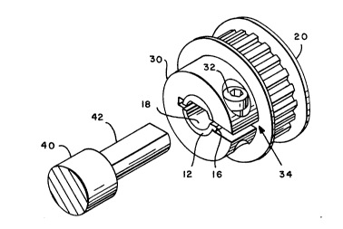
Fig. 1 is an exploded isometric view of a split
collar clamp, a hub and a drive component which comprise an
embodiment of the present invention;
Fig. 2 is an isometric view of the clamp, hub and
drive component of Fig. 1 assembLed for mounting on a drive
shaft;
Fig. 3 is an end view of the device in Fig. 1 secured
on the drive shaft; and
Fig. 4 is an isometric view of a tvpical application
of the present invention.
Detailed Descript$on of the Pre~ent Invention
The Figures show the preferred embodiment of the
present invention, in which a hub 10 and clamp collar 30 are
used to secure a mechanical drive component, such as a
commercial timing pulley 20 to a drive shaft 40.
Fig. 1 shows hub 10 which has an extended member 12
which is slotted and a hub member 14 which is knurled.
Slotted member 12 includes a locator rib 16 situated at one
of the slots. In the preferred embodiment of the present
invention, hub 10 is a high density powder metal hub which
has a D-shaped hole 18 for locking on to a "D" shaped
portion 42 of drive shaft 40. Clamp collar 30 is split
collar clamp which slides over the slotted member 12 of hub
10. Clamp collar 30 includes a set screw 32 which passes
through a split portion 34 of clamp 30. Rib 16 of hub lo
engages the split portion 34 of collar 30 and in doing so
maintains the orientation between collar 30 and hub 10 when
set screw 32 is tightened.
It has been discovered that a hub having a slotted
member with the locator rib and having a hole matching the
shape of the shaft can be locked in place by a split collar
clamp to significantly reduce the wear on the shaft
typically experienced from repeated stop and go operation.
It has been discovered that the present invention works for
various shaped shafts including round shafts.
2~2220
- 6 -
Referring now to Figs. 2 and 3, hub 10 has been
inserted into the hole of pulley 20 and collar 30 has been
placed over the slotted member 12 of hub 10. In the
preferred embodiment of the present invention, pulley 20 is
secured to knurled member 14 of hub 10 by interference or
pressed fit. It has been found that the pressed fit between
hub 10 and pulley 20 provides a more reliable fastening than
the use of set 6crews which are known to become loose when
subjected to repeated ~top and go operation. It will be
understood that alternate methods of coupling pulley 20 to
hub 10 can also be use. For example, for components made of
softer material, such as urethane, an epoxy can be added
during the pressed fit to strengthen the bond between the
two materials.
Any commercially available drive component can be
used in conjunction with the present invention. A hole is
bored into the drive component at a diameter slightly
smaller than the outer diameter of the knurled member 14 of
hub 10. In the preferred embodiment of the present
invention, for a 3/8 inch diameter shaft the outer diameter
of the knurled member is between .5675 to .5695 inches and
the hole bored into the drive component iB between .562 to
.563 inches. The knurled member is then interference fit
into the bored hole in the component.
It will be understood by those skilled in the art
that the present invention is suitable for any mechanical
drive component which is driven by a drive shaft. For
example, hub 10 and collar 30 can be used to secure gears,
sprockets or cams.
It has been found that the present invention provides
an easy and reliable method of securing commercially
available drive components, 6uch as pulley 20, to drive
shafts without having to mar the shaft by drilling into the
shaft or tightening a set screw against the shaft. The
present invention has been found to be particularly suitable
for use in machines where the mechanical drive components
are repeatedly subjected to fluctuations in load caused, for
2062220
7 --
example, by continuous stop and go or deceleration and
acceleration movement, such as the clutch and brake
operation in an inserter machine. It has also been found
that the present invention provides the added advantage of
facilitating adjustments to the lateral positioning of the
component on the drive shaft.
It will be appreciated by those skilled in the art
that the terms "drive shaft" and "drive component", as used
herein to describe the present invention, includes driven
shafts and driven components.
~- Referring now to Fig. 4, a typical application of the
present invention is shown. Timing pulley 20 is mounted on
drive shaft 40 by hub lO and clamp 30. Timing belt 50
operates in conjunction with timing pulley 20 to drive
driven pulley 20' which is mounted on driven shaft 40' by
hub 10' and collar 30'. Drive shaft 40 and driven shaft '40
may be used for driving rollers in a bursting apparatus.
It will be appreciated that there has been provided
in accordance with the present invention a device for
securely locking mechanical drive components to a drive
shaft that fully satisfies the objects, aims and advantages
set forth above. While this in this invention has been
described in conjunction with specific embodiments thereof,
many alternatives, modifications and variations will be
apparent to those skilled in the art. Accordingly, it is
intended to embrace all such alternatives, modifications and
variations that follow within the spirit and scope of the
appended claims.