Note: Descriptions are shown in the official language in which they were submitted.
2062305
FI~LD OF T~E lh~ lON
The present invention relates to a humidity control apparatus
which has plural functions of dehumidification, humidification and
ventilation.
BBIFF DFSC~IPTION OF T~E P~IO~ A~T
A conventional humidity control apparatus which has the dual
functions of dehumidifier and humidifier is disclosed by the Japanese
published unexamined patent application No. Sho 63-286634 (Tokkai Sho
63-286634). Although more fully described hereinafter, the
conventional dry-type humidity control apparatus, which needs neither a
water supply nor drain, comprises a solid adsorber, a heater, a fan and
bi-directional control valves. The fan provides a flow of air in a
room and the heater is arranged at the upstream side of the solid
adsorber in the air-flow stream. This conventional humidity control
apparatus adsorbs moisture from the exterior air as the first step of
humidification. During the adsorption process, the bi-directional
control valves are positioned so that outdoor air is sucked into the
humidity control apparatus through an exterior inlet port and is
discharged through an exterior outlet port after its passing through
the solid adsorber. When the outdoor air passes through the solid
adsorber, the moisture which is contained therein is adsorbed by the
solid adsorber.
After the above-mentioned humidity adsorption process is performed
in the humidification operation, the conventional humidity control
apparatus performs a desorption process in the humidification operation
for discharging the adsorbed moisture into the room. In the desorption
process, the directional control valves are re-positioned so that room
air is sucked into the humidity control apparatus through an interior
inlet port and discharged back into the room through an interior outlet
port after the air passes through the solid adsorber. When the room
air passes through the solid adsorber, the latter is dried by the
sucked air which is heated by the heater. As a result, the moisture of
the solid adsorber is desorbed by the heated air, and the heated
humidified air is discharged into the room. As mentioned above, the
moisture is fed from the interior outlet port to the air in the room.
By alternately operating the aforementioned adsorption and desorption
2062306
processes, the moisture in the solid adsorber is supplied to the room
air, which is thereby humidified.
However, the above-mentioned conventional humidity control
apparatus has the following problems:
(1) The conventional humidity control apparatus uses a Thermal Swing
Adsorption system (TSA) in the desorption process of the humidification
operation, for speedy drying of the solid adsorber. The solid adsorber
in the desorption process is dried by the sucked room air having a
higher temperature than the temperature of the outdoor air sucked into
the humidity control apparatus during the adsorption process.
Therefore, the conventional humidity control apparatus in the
desorption process has such losses as (i) heat exchange loss when the
internal air is heated by the heater, (ii) radiation loss when the
heated air is passing in the air-flow stream in the humidity control
apparatus, and (iii) heat loss when the solid adsorber is dried by the
heated air. As a result, a large quantity of the heat energy is
consumed in the desorption process, which thereby increases the cost of
operation.
Further, since the solid adsorber is indirectly heated by the warm
air which is heated by the heater, the conventional humidity control
apparatus requires a long rise time period before reaching the state of
heating of the solid adsorber in the desorption process. Accordingly,
the conventional humidity control apparatus, which alternately carries
out the adsorption process and the desorption process, has only a low
humidification ability due to the low efficiency of the desorption
process which requires a long time. If the apparatus were designed so
that the time period for the desorption process were selected to be
short, a large solid adsorber and a large power heater must be used in
the conventional humidity control apparatus in order to achieve
sufficiently high humidification capability.
(2) Though the conventional humidity control apparatus has inlet and
outlet ducts communicating between the outdoor air and the room air,
the conventional humidity control apparatus cannot carry out a
ventilation function.
(3) In the humidification operation of the conventional humidity
control apparatus, the solid adsorber adsorbs moisture from the outdoor
~0`62306
air, and the adsorbed moisture is discharged to the room air by the air
passed through the solid adsorber. At the same time, the solid
adsorber also adsorbs atmospheric nitrogen with moisture. Though the
volume of the adsorbed nitrogen varies depending upon the type of solid
adsorber, the adsorbed nitrogen [N2] is discharged to the room air
together with the moisture, in the humidification operation of the
conventional humidity control apparatus. As a result, the
concentration or relative volume of oxygen in the internal air
decreases, while the moisture content of the internal air is increased.
OBJECT AND SUMMA~Y OF THE lr.~k~lloN
An object of the present invention is to provide an automatic
humidity control apparatus which can automatically and appropriately
carry out all of the functions of humidification, dehumidification and
ventilation of the internal air of a room to be controlled.
In order to achieve the above-mentioned object, the humidity
control apparatus of the present invention comprises:
an adsorber unit which is provided in an air-flow stream to adsorb
moisture from the air,
a heater which heats the adsorber unit to desorb moisture in the
adsorber unit,
a fan for generating internal air flow or external air flow toward
the adsorber unit,
an intake damper which is provided at an upstream side of the
adsorber unit and is positioned to close an internal-air inlet port or
an external-air inlet port in accordance with a selected operation mode,
an exhaust damper which is provided at a downstream side of the
adsorber unit and is positioned to close an internal-air outlet port or
an external-air outlet port in accordance with a selected operation
mode, and
a controller which controls operations of the heater, the fan, the
intake damper and the exhaust damper in accordance with a selected
operation mode, the controller being adapted for selecting either one
of the following operation modes:
(i) a dehumidification operation mode including
2~2:~06
an adsorption process whereby moisture from internal air is
adsorbed into the adsorber unit and, thereafter, the internal air is
discharged to an interior space, and
a desorption process whereby the heater and the fan are
energized to cause an air flow of exterior air to the adsorber unit to
desorb moisture from the adsorber unit and, thereafter, the external
air is discharged to an exterior space; and
(ii) a humidification operation mode including
an adsorption process whereby moisture from external air is
adsorbed into the adsorber unit and, thereafter, the external air is
discharged to the exterior space, and
a desorption process whereby the heater and the fan are
energized to cause an air flow of internal air to the adsorber unit to
desorb moisture from the adsorber unit and, thereafter, the internal
air is discharged to the interior space.
The humidity control apparatus of the present invention has such
advantages as economically superior cost, easy maintenance, and
effective operations of humidification, dehumidification and
ventilation for a room to be controlled.
The invention will hereinafter de described more fully by way of
example only and with reference to the accompanying drawings.
BBIEF DESCBIPTION OF T~E DBAWINGS
FIG.l is a sectional view showing a non-operation state of a
humidity control apparatus of the present invention
FIG.2 is a block diagram showing components of the humidity
control apparatus shown in FIG.l
FIG.3 is a sectional view showing a desorption process in the
dehumidification operation of the humidity control apparatus shown in
FIG.l.
FIG.4 is a sectional view showing an adsorption process in the
dehumidification operation of the humidity control apparatus shown in
FIG.l
FIG.5 is a sectional view showing a desorption process in the
dehumidification operation with ventilation of the humidity control
apparatus shown in FIG.l
i- 2062306
FIG.6 is a sectional view showing an adsorption process in the
dehumidification operation with ventilation of the humidity control
apparatus shown in FIG.l.
FIG.7 is a sectional view showing an adsorption process in the
humidification operation of the humidity control apparatus shown in
FIG.l.
FIG.8 is a sectional view showing a desorption process in the
humidification operation of the humidity control apparatus shown in
FIG.l.
FIG.9 is a sectional view showing an adsorption process in the
humidification operation with ventilation of the humidity control
apparatus shown in FIG.l.
FIG.10 is a sectional view showing a desorption process in the
humidification operation with ventilation of the humidity control
apparatus shown in FIG.l.
FIG.ll is a flowchart illustrating the operation of the humidity
control apparatus shown in FIG.l.
FIG.12 is a sectional view of the conventional humidity control
apparatus.
It will be recognized that some or all or the Figures are
schematic representations for purposes of illustration and do not
necessarily depict the actual relative sizes or locations of the
elements shown.
nRTATT.Rn DESCKIPTION OF P~IO~ ABT
The conventional humidity control apparatus of the dry type, as
briefly described above, is shown in FIG.12, which is a cross-sectional
view. As shown in FIG.12, the conventional humidity control apparatus
comprises a solid adsorber 31, a heater 32, a fan 33 and bi-directional
control valves 34a, 34b. The fan 33 is provided to create a flow of
air in a room in a direction shown by arrows X in FIG.12. The heater 32
is arranged at the upstream side of the solid adsorber 31 in the
air-flow stream. The above-mentioned conventional humidity control
apparatus carries out an adsorption process, whereby moisture is
adsorbed from the exterior air, in the first step of humidification.
In the adsorption process, the bi-directional control valves 34a, 34b
20b~305
are turned to the positions shown by alternate long and short dash
lines in FIG.12. As a result, an interior inlet port 35 and an interior
outlet port 36 are closed by the control valves 34a, 34b, respectively,
and external air from the exterior space (i.e., outdoor air) is sucked
into the humidity control apparatus through the exterior inlet port
37. The sucked air is discharged to the exterior space through an
exterior outlet port 38 after its passing through the solid adsorber
31. When the external air passes through the solid adsorber 31, the
moisture which is contained in the sucked air is adsorbed by the solid
adsorber 31.
After the above-mentioned humidity adsorption process is performed
in the humidification operation, the conventional humidity control
apparatus performs a desorption process in the humidification operation
for discharging the adsorbed moisture into the room. In the desorption
process, the bi-directional control valves 34a, 34b are turned to the
other positions which are shown by solid lines in FIG.12. As a result,
the exterior inlet port 37 and the exterior outlet port 38 are closed
by the control valves 34a, 34b, respectively, and the internal air
(room air) is sucked into the humidity control apparatus through the
interior inlet port 35. The sucked air in the humidity control
apparatus is discharged to the room through the interior outlet port 36
after the sucked air passes through the solid adsorber 31. As the
internal air passes through the solid adsorber 31, the solid adsorber
31 is dried by the sucked air which is heated by the heater 32. As a
result, the moisture of the solid adsorber 31 is desorbed by the heated
air, and the heated humidified air is discharged into the room. As
mentioned above, the moisture is fed from the interior outlet port 36
to the air in the room. By alternately operating the aforementioned
adsorption and desorption processes, the moisture in the solid adsorber
31 is supplied to the room air, which is thereby humidified.
As stated above, this conventional humidity control apparatus has
the following problems:
(1) The conventional humidity control apparatus uses a Thermal Swing
Adsorption system (TSA) in the desorption process of the humidification
operation, which is used for speedy drying of the solid adsorber 31.
The solid adsorber 31 in the desorption process is dried by the sucked
2062306
internal (room) air having a higher temperature than the temperature of
the external (outdoor) air sucked into the humidity control apparatus
during the adsorption process. Therefore, the conventional humidity
control apparatus in the desorption process has such losses as, (i)
heat exchange loss when the internal air is heated by the heater 32,
(ii) radiation loss when the heated air passes through the humidity
control apparatus, and (iii) heat loss when the solid adsorber 31 is
dried by the heated air. As a result, a large quantity of the heat
energy is consumed and lost in the desorption process of the
conventional humidity control apparatus, which thereby increases the
cost of operation.
Further, since the solid adsorber 31 is indirectly heated by the
warm air which is heated by the heater 32, there is a long rise time
period until to the solid adsorber 31 reaches the heated state in the
desorption process. Accordingly, this conventional humidity control
apparatus, which alternately carries out the adsorption process and the
desorption process, has only a low humidification ability due to the
low efficiency of the desorption process which requires a long time.
If the apparatus were designed so that the time period for the
desorption process were selected to be short, a large solid adsorber
and a large power heater would be needed in order to achieve a high
humidification capability.
(2) Though the conventional humidity control apparatus has inlet and
outlet ducts communicating between the external air and the internal
air, it cannot carry out a ventilation function.
(3) In the humidification operation of the conventional humidity
control apparatus, the solid adsorber 31 adsorbs moisture from the
external air, and the adsorbed moisture is discharged to the room air
by the air passing through the solid adsorber 31. At the same time,
the solid adsorber 31 also adsorbs atmospheric nitrogen with moisture.
Though the volume of the adsorbed nitrogen varies depending upon the
type of solid adsorber 31, the adsorbed nitrogen is discharged to the
internal air together with the moisture in the humidification
operation. As a result, the concentration of oxygen in the room air
3S decreases, while the moisture in the room air is increased.
2~3 ~
DESC~IPTION OF THE KK~KK~U EMBODIMENTS
Hereafter, a preferred embodiment of a humidity control apparatus
of the present invention is described with reference to the
accompanying drawings of FIGs.l to 11.
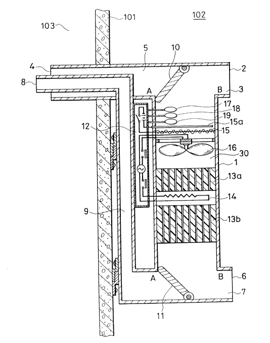
FIG.l is a sectional view showing a non-operation state of a
humidity control apparatus according to one embodiment of the present
invention. As shown in FIG.l, a casing 1 of the humidity control
apparatus is installed upon a wall 101 which partitions between an
interior space 102, such as a room in a house, and an exterior space
103. An internal-air inlet passage 3, which has an internal-air inlet
port 2, and an external-air inlet passage 5, which has an external-air
inlet port 4, are provided at an upper portion of the casing 1. The
external-air inlet passage 5 is provided by boring through the wall
101. In a lower portion of the casing 1, an internal-air outlet
passage 7 having an internal-air outlet port 6 is provided to discharge
air to the interior space 102. An external-air outlet passage 9 has an
external-air outlet port 8 communicating with the exterior space 103.
In at least the through-wall portion of the external-air outlet passage
9, the external-air outlet passage 9 is arranged in the above-mentioned
external-air inlet passage 5 in the upper portion of the casing 1.
Therefore, the through-wall portion of the passage is constructed by a
double tube structure. An intake damper 10 for controlling the inlet
direction of the air is rotatably provided at an upper branching part
between the internal-air inlet passage 3 and the external-air inlet
passage 5 of the casing 1. A switchable exhaust damper 11 for
controlling the outlet direction of the air is provided at a lower
branching part between the internal-air outlet passage 7 and the
external-air outlet passage 9 of the casing 1. The intake damper 10 and
the exhaust damper 11 are operated by a damper drive unit (not shown).
The damper drive unit is driven by a control motor, such as a pulse
motor which is controlled by a control signal from a controller 12. In
an intermediate passage 30, which connects the inlet passage of the
upper casing portion to the outlet passage of the lower casing portion,
a first solid adsorber 13a and a second solid adsorber 13b are disposed
with a predetermined spacing therebetween. The first solid adsorber
13a and the second solid adsorber 13b function to adsorb the moisture
2062306
from the air, and also have the function of an evaporator for desorbing
the moisture by heating. The first solid adsorber 13a and the second
solid adsorber 13b, which are made of zeolite or silica gel, are formed
in a corrugated shape or a honeycomb shape. The first solid adsorber
13a, which is arranged towards the upstream end of the intermediate
passage 30, is selected to have a smaller volume than the second solid
adsorber 13b, which is arranged towards the downstream end of the
intermediate passage 30. A heater 14 for heating the first solid
adsorber 13a and the second solid adsorber 13b is disposed close to and
between the first solid adsorber 13a and the second solid adsorber
13b. When the dehumidification operation, the humidification operation
and the like are performed by the humidity control apparatus of the
present invention, the heater 14 is electrified to heat the first solid
adsorber 13a mainly by radiation and the second solid adsorber 13b
mainly by conduction through air flow, thereby making the moisture
thereon desorb therefrom. A conventional electrically charged filter
15 for cleaning the sucked air is arranged at the upstream side of the
fan 16, which blows the cleaned internal air or the cleaned external
air into the first solid adsorber 13a and the second solid adsorber
13b. As shown in FIG.l, a temperature sensor 17, a moisture sensor 18
and an oxygen sensor 19 are arranged adjacent charged filter 15 and at
the upper end of the intermediate passage 30. The temperature sensor
17 is provided for detecting the temperature of the sucked internal air
and the sucked external air. The moisture sensor 18 is provided for
detecting the moisture in the sucked air, and the oxygen sensor 19 is
provided for detecting the concentration of oxygen in the sucked air.
A controller 12 receives output signals from these sensors, and
controls operations of the intake damper 10, the exhaust damper 11, the
heater 14 and the fan 16.
FIG.2 is a block diagram of the main components of the
above-described humidity control apparatus. The controller 12 compares
the detected signals of the temperature sensor 17, the moisture sensor
18 and the oxygen sensor 19 with the predetermined reference data of
temperature, humidity and concentration of oxygen. The controller 12
also controls the operation of the intake damper 10, the exhaust damper
11, the heater 14 and the fan 16 in accordance with the results of the
- 2062306
- 10 -
comparison of the detected signals with the predetermined reference
values. The current positions of the intake damper 10 and exhaust
damper 11 are detected by damper position sensors 20, and the detected
position signals of the damper position sensors 20 are inputted to the
controller 12 as a feedback control loop.
Next, the basic operation of the above-mentioned humidity control
apparatus is described with reference to FIG.l.
When a power supply switch (not shown) of the humidity control
apparatus is closed, the fan 16 rotates with the apparatus in the
condition shown in FIG.l. In other words, the fan 16 is driven with
the intake damper lO arranged at position A to close the external-air
inlet passage 5 and the exhaust damper 11 arranged at position A to
close the external-air outlet passage 9. As a result, internal air of
the room to be controlled is sucked in through the internal-air inlet
port 2 and passes over the temperature sensor 17, the moisture sensor
18 and the oxygen sensor 19. The temperature, the humidity and the
oxygen concentration in the sucked internal air are reliably detected
by these sensors. The detected data of the temperature, the humidity
and the oxygen concentration in the internal air are transferred to the
controller 12. According to the detected data, the humidity control
apparatus of the present invention performs an arithmetic operation,
and selects an appropriate operation mode from the following four kinds
of operations:
In a first case where the detected relative humidity in the
internal air is higher than 60% and the detected oxygen concentration
in the internal air is no less than a predetermined value, such as 20%,
the controller 12 calls for a dehumidification operation.
In a second case where the detected relative humidity in the
internal air is higher than 60~o and the detected oxygen concentration
in the internal air is less than a predetermined value, such as 20%,
the controller 12 calls for a dehumidification operation with
ventilation.
In a third case where the detected relative humidity in the
internal air is less than 40%, and the detected oxygen concentration in
the internal air is no less than a predetermined value, such as 20%,
the controller 12 calls for humidification operation.
2062306
In a fourth case where the detected relative humidity in the
internal air is less than 40% and the detected oxygen concentration in
the internal air is less than a predetermined value, such as 20%, the
controller 12 calls for a humidification operation with ventilation.
Next, the above-mentioned four kinds of operation - that is,
dehumidification without ventilation, dehumidification with venti-
lation, humidification without ventilation and humidification with
ventilation - will be described with reference to FIGs.3 to 11.
Hereafter, the "dehumidification without ventilation" and
"humidification without ventilation" are simply referred to as
"dehumidification" and "humidification" for brevity.
Dehumidification Operation
When the controller 12 of the humidity control apparatus judges,
based on the detected data of the temperature sensor 17, the moisture
lS sensor 18 and the oxygen sensor 19, that the dehumidification operation
should be set in motion, the controller 12 orders the start of a first
step of a desorption process. In the desorption process, the moisture
which is contained in the first solid adsorber 13a and the second solid
adsorber 13b is desorbed by heating. When the controller 12 orders the
start of the dehumidification operation, it is necessary to make
desorption of the first solid adsorber 13a and the second solid
adsorber 13b, since these already contain the moisture of the internal
air of the room owing to natural convection in the room. Therefore,
the moisture of the first solid adsorber 13a and the second solid
adsorber 13b needs to be desorbed in the first step by using the
desorption process.
Desorption Process In Dehumidification Operation
In the first step of the desorption process, the intake damper 10
and the exhaust damper 11 are turned to close the internal-air inlet
passage 3 and the internal-air outlet passage 7, respectively. FIG.3
illustrates the desorption part of the dehumidification operation. As
shown in FIG.3, the intake damper 10 and the exhaust damper 11 are
turned to position B by the above-mentioned damper drive unit, which
has a pulse motor. In the above-mentioned condition shown in FIG.3,
when the controller 12 initiates the operation of the fan 16 and the
heater 14, the external air sucked from the external-air inlet port 4
2062306
- 12 -
is heated by the heater 14, and becomes high temperature or heated
air. The first solid adsorber 13a is heated directly by the heat
generated by the heater 14, and the second solid adsorber 13b is heated
by the high temperature air. Since the heater 14 is disposed at a
position close to and between the first solid adsorber 13a and the
second solid adsorber 13b, almost all of the heat energy generated by
the heater 14 is efficiently received and absorbed by the first solid
adsorber 13a and the second solid adsorber 13b. The first solid
adsorber 13a and the second solid adsorber 13b, which are efficiently
heated by the radiant heat and the high temperature air flow, desorb
the absorbed moisture. The desorbed moisture is discharged from the
external-air outlet port 8. When a predetermined time interval lapses
after start of energization of the heater 14, the first solid adsorber
13a and the second solid adsorber 13b are in the desorbed state. When
the first solid adsorber 13a and the second solid adsorber 13b reach
the desorbed state, the controller 12 orders the operation of the
heater 14 to stop but keeps the fan 16 operating. The fan 16 continues
to be operated until the temperature of the first solid adsorber 13a
and the second solid adsorber 13b reach such a low temperature that the
first solid adsorber 13a and the second solid adsorber 13b can again
absorb moisture from the internal air of the room. After the fan 16
has been operated for a predetermined time interval, the fan 16 is
stopped, and the desorption part of the dehumidification operation is
finished.
Adsorption Process In Dehumidification Operation
Next, the controller 12 orders an adsorption process in the
dehumidification operation. In the adsorption process, the moisture in
the sucked air is adsorbed by the first solid adsorber 13a and the
second solid adsorber 13b. FIG.4 illustrates the operation of the
adsorption process in the dehumidification operation. As shown in
FIG.4, the intake damper 10 and the exhaust damper 11 are turned to
position A to close the external-air inlet passage S and the
external-air outlet passage 9, respectively. In the above-mentioned
conditions shown in FIG.4, the controller 12 initiates the operation of
the fan 16. As a result, the internal air from the interior space 102
is sucked through the casing 1 from the internal-air inlet port 2, and
2062306
-
floating dust and particles in the sucked air are attracted by the
charged filter 15 charged by the discharge wire 15a. Since the
moisture in the sucked air is absorbed by the first solid adsorber 13a
and the second solid adsorber 13b, pure dry air is supplied from the
internal-air outlet port 6 to the interior space 102 to be
dehumidified. The length of the predetermined time interval for
supplying the pure dry air to the room is selected by the controller 12
which takes account of the absorption capacities of the first solid
adsorber 13a and the second solid adsorber 13b, the detected relative
humidity of the internal air, the heat-radiation capacity of the heater
14, the ventilation capacity of the fan 16 and the size of the room to
be serviced.
The humidity control apparatus of the present invention can
perform the dehumidification operation for the internal air of the
interior space 102 by alternately carrying out the aforementioned
desorption and adsorption processes, by switching the positions of the
dampers 10 and 11 in synchronism with the alternation between the
adsorption and the desorption. The humidity control apparatus of the
present invention is advantageous in its easy handling of the
dehumidification operation. Also, the humidity control apparatus can
perform an energy-saving dehumidification operation with a high heat
efficiency because of the arrangement of the heater 14 between the
first solid adsorber 13a and the second solid adsorber 13b.
Apart from the above-mentioned embodiment of the humidity control
apparatus which is operated at a normal capacity in the
dehumidification operation, a modified embodiment may be such that the
dehumidification operation is operated at a maximum capacity of the
humidity control apparatus until the humidity of the room quickly
reaches a predetermined value. In the case where the detected humidity
of the room is out much different from the predetermined reference
humidity value, such humidity control apparatus would have a high
efficiency. In order to operate the humidity control apparatus at the
~ ; , capacity of the dehumidification operation, the heater 14 is
controlled to perform the ~i heat-generation in the desorption
process, while in the adsorption process, the fan 16 is controlled to
work at the maximum ventilation capacity.
- 2062306
Furthermore, the humidity control apparatus may be operated at a
lowered - or in some cases, minimum - capacity of the dehumidification
operation to adjust for small fluctuations of the humidity of the room,
once the internal humidity has reached the predetermined humidity
value. In order to operate the humidity control apparatus at the
lowered or rini I capacity of the heater 14, and the adsorption
process is operated at the ini I ventilation capacity of the fan 16.
As result, this humidity control apparatus of the present invention has
an advantage of power-saving in case of quick but small fluctuations of
humidity in the room.
Dehumidification Operation With Ventilation
When the controller 12 of the humidity control apparatus judges
from the detected data of the temperature sensor 17, the moisture
sensor 18 and the oxygen sensor 19 that dehumidification together with
ventilation should be operated, the controller 12 initiates the
dehumidification operation together with ventilation. The
dehumidification operation with ventilation is the operation mode
wherein the humidity of the internal air of the interior space 102 is
decreased to reach the predetermined reference humidity, and at the
same time, the internal air in the interior space 102 is ventilated.
Desorption Process In Dehumidification Operation With Ventilation
In the first step of the dehumidification operation with
ventilation, the controller 12 orders the start of a desorption process
for desorbing the moisture of the first solid adsorber 13a and the
second solid adsorber 13b. FIG.5 shows the operation state during the
desorption process. As shown in FIG.5, the intake damper 10 is
positioned to the position A so as to close the external-air inlet
passage 5, and the internal air of the interior space 102 is sucked
through the internal-air inlet passage 3. The exhaust damper 11 is
moved to the position B for discharging the sucked internal air to the
exterior space 103. The fan 16 and the heater 14 are energized upon
the order of the controller 12. As a result, the moisture which is
contained in the first solid adsorber 13a and the second solid adsorber
13b is desorbed by the radiant heat and the high temperature air flow
by the operation of the heater 14 and the fan 16, and the desorbed
2062306
moisture is discharged from the external-air outlet port 8. When the
predetermined time interval has lapsed after the energization of the
heater 14, the first solid adsorber 13a and the second solid adsorber
13b are in the desorbed state. When the first solid adsorber 13a and
second solid adsorber 13b reach the desorbed state, the controller 12
orders the operation of the heater 14 to stop, but keeps the fan 16
operating. The fan 16 operates to cool the first solid adsorber 13a
and the second solid adsorber 13b for a predetermined time interval.
Adsorption Process In Dehumidification Operation With Ventilation
Next, the controller 12 orders the start of an adsorption process
in the dehumidification operation with ventilation. FIG.6 shows the
operation state of the adsorption process in the dehumidification
operation with ventilation. As shown in FIG.6, the intake damper 10 is
turned to the position B, and the exhaust damper 11 is turned to the
position A.
In the above-mentioned condition shown in FIG.6, the controller 12
initiates operation of the fan 16. As a result, the external air is
sucked into the casing 1 through the external-air inlet port 4, and
floating dust and particles in the sucked external air are attracted by
the charged filter 15. Since the moisture in the sucked external air
is absorbed by the first solid adsorber 13a and the second solid
adsorber 13b, the pure dry air is supplied from the internal-air outlet
port 6 to the interior space 102 to be dehumidified for a predetermined
time interval. The predetermined time interval for supplying pure dry
air to the interior space 102 is selected by the controller 12, which
takes account of the absorption capacities of the first solid adsorber
13a and the second solid adsorber 13b, the detected relative humidity
of the internal air, the heat-radiation capacity of the heater 14, the
ventilation capacity of the fan 16 and the size of the room to be
serviced.
The above-described humidity control apparatus of the present
invention can perform the dehumidification operation together with
ventilation of the interior space 102 by alternately operating the
aforementioned desorption process and adsorption process. Furthermore,
the humidity control apparatus can remove contA lnAnts from the
2062306
internal air of the interior space 102 by operating the ventilation
together with the dehumidification operation.
Humidification Operation
When the controller 12 of the humidity control apparatus judges,
based on the detected data of the temperature sensor 17, the moisture
sensor 18 and the oxygen sensor 19, that the humidification operation
should be initiated, the controller 12 orders start of an adsorption
process in the humidification operation. In other words, when the
relative humidity in the interior space 102 is less than 40%, and the
oxygen concentration is higher than a predetermined value, the
controller 12 orders the start of the adsorption process in the
humidification operation. When the controller 12 orders the start of
the adsorption process, the first solid adsorber 13a and the second
solid adsorber 13b already contain some moisture from the internal air
of the room owing to natural convection in the room. However, the
adsorption process is further performed in a first step of the
humidification operation in order to absorb moisture from the internal
air to the point of saturation. Thus, the first adsorption process is
operated until the first solid adsorber 13a and the second solid
adsorber 13b are saturated with moisture from the internal air. As
mentioned above, the humidification operation is started from the
adsorption process. Therefore, the time interval for the first
adsorption process in the humidification operation may be selected to
be shorter than that of a second adsorption process thereafter.
Adsorption Process In Humidification Operation
In the first step of the adsorption process, the intake damper 10
and the exhaust damper 11 are turned to close the internal-air inlet
passage 3 and the internal air outlet passage 7, respectively. FIG.7
shows the operating state of the adsorption process in the
humidification operation. As shown in FIG.7, the intake damper 10 and
the exhaust damper 11 are turned to the position B by the pulse motor
of the damper drive unit. In the above-mentioned condition shown in
FIG.7, the controller 12 orders start of the operation of the fan 16.
As a result, the external air from the exterior space 103 is sucked
into the casing 1 through the exterior-air inlet port 4, and floating
dust and particles in the sucked external air are attracted by the
2062306
electrically charged filter 15, which is charged by the discharge wire
15a. The moisture in the sucked external air is absorbed by the first
solid adsorber 13a and the second solid adsorber 13b for a
predetermined time interval. The predetermined time interval for the
adsorption process is selected by the controller 12, which takes
account of the absorption capacities of the first solid adsorber 13a
and the second solid adsorber 13b, the detected relative humidity of
the internal air, the heat-radiation capacity of the heater 14, the
ventilation capacity of the fan 16, and the size of the room to be
serviced.
Desorption Process In Dehumidification Operation
Next, the controller 12 orders initiation of a desorption process
in the humidification operation. FIG.8 illustrates the desorption
process in the humidification operation. As shown in FIG.8, the intake
damper 10 and the exhaust damper 11 are arranged to close the
external-air inlet passage 5 and the external-air outlet passage 9. In
other words, the intake damper 10 and the exhaust damper 11 are
respectively turned to position A by the damper drive unit. Under the
conditions shown in FIG.8, when the controller 12 orders start of the
operation of the fan 16 and the heater 14, the internal air sucked from
the internal-air inlet port 2 is heated by the heater 14, and becomes
high temperature or heated air. The first solid adsorber 13a is heated
directly by the heat generated by the heater 14, and the second solid
adsorber 13b is heated by the high temperature air produced by the
heater 14. The first solid adsorber 13a and the second solid adsorber
13b are efficiently heated, thereby to desorb the adsorbed moisture of
the first solid adsorber 13a and the second solid adsorber 13b. The
desorbed moisture is discharged from the internal-air outlet port 6 in
order to humidify the interior space 102. When the predetermined time
interval has elapsed after energization of the heater 14, the
controller 12 orders the operation of the heater 14 to stop, but keeps
the fan 16 operating. The fan 16 continues to be operated until the
predetermined time interval has passed. When the predetermined time
interval for cooling has elapsed, the fan 16 is stopped, and the
desorption process in the humidification operation has finished.
- 2062306
The above-mentioned humidity control apparatus of the present
invention can perform the humidification of the internal air of the
interior space 102 by alternately operating the aforementioned
adsorption process and desorption process.
Apart from the above-mentioned embodiment of the humidity control
apparatus which is operated at normal capacity in the humidification
operation, a modified embodiment may be such that the humidification
operation is operated at a maximum capacity of the humidity control
apparatus until the humidity of the room quickly reaches a
predetermined value. In the case where the detected humidity of the
room is very much higher than the predetermined reference humidity
value, this humidity control apparatus would have great effect.
Furthermore, the humidity control apparatus may be operated to
humidify at its minimum capacity for a small change in the humidity of
the room, after the internal humidity once reaches the predetermined
humidity value.
~umidification Operation With Ventilation
When the controller 12 of the humidity control apparatus judges,
based on the detected data of the temperature sensor 17, the moisture
sensor 18 and the oxygen sensor 19, that humidification together with
ventilation should be effected, the controller 12 orders initiation of
the humidification operation with ventilation. In the humidification
operation with ventilation, the humidity of the internal air of the
interior space 102 is increased until the predetermined reference
humidity is reached, and the internal air in the interior space 102 is
ventilated at the same time.
In the first step of the humidification operation with
ventilation, the controller 12 orders initiation of an adsorption
process for absorbing moisture from the internal air into the first
solid adsorber 13a and the second solid adsorber 13b until the first
solid adsorber 13a and the second solid adsorber 13b are saturated with
moisture from the internal air.
Adsorption Process In Humidification Operation With Ventilation
In the first step of the adsorption process, the intake damper 10
and the exhaust damper 11 are turned to close the external-air inlet
passage 5 and the internal air outlet passage 7, respectively. FIG.9
2062306
- 19 -
shows the operating state of the adsorption process in the
humidification operation with ventilation. As shown in FIG.9, the
intake damper 10 is arranged at the position A by the damper drive
unit, and the exhaust damper 11 is arranged at the position B. In the
S above-mentioned condition shown in FIG.9, the controller 12 orders
initiation of the operation of the fan 16. As a result, the
internal-air of the interior space 102 is sucked through the
internal-air inlet port 2 into the casing 1, and the sucked internal
air is discharged from the external-air outlet port 8 through the
charged filter 15, the first solid adsorber 13a and the second solid
adsorber 13b. The adsorption process in the humidification operation
with ventilation is operated for a predetermined time interval which is
selected by taking account of the absorption capacities of the first
solid adsorber 13a, the second solid adsorber 13b, the size of the room
to be serviced, etc.
Desorption Process In Humidification Operation With Ventilation
Next, the controller 12 initiates a desorption process in the
humidification operation with ventilation. FIG.10 shows the operating
state of the desorption process in the humidification operation with
ventilation. As shown in FIG.10, the intake damper 10 is turned to the
position B, and the exhaust damper 11 is turned to the position A.
In the above-mentioned condition shown in FIG.10, the controller
12 orders start of the operation of the fan 16 and the heater 14. As a
result, the external air, which is sucked from the external-air inlet
port 4, is heated by the heater 14. The first solid adsorber 13a is
directly heated by the heat generated by the heater 14, and the second
solid adsorber 13b is heated by the high temperature air. Therefore,
the absorbed moisture in the first solid adsorber 13a and the second
solid adsorber 13b is desorbed by heat generated by the heater 14 and
the high temperature air flow. The desorbed moisture is discharged
through the internal-air outlet port 6 to the internal air. When the
predetermined time interval has elapsed after energization of the
heater 14, the first solid adsorber 13a and the second solid adsorber
13b are in the desorbed state. When the first solid adsorber 13a and
the second solid adsorber 13b reach the desorbed state, the controller
12 orders the operation of the heater 14 to stop, but keeps the fan 16
2062306
- 20 -
operating. Then, the fan 16 operates for cooling the first solid
adsorber 13a and the second solid adsorber 13b for the predetermined
time interval.
The above-mentioned humidity control apparatus of the present
invention can perform the humidification operation together with
ventilation for the internal air of the interior space 102 by
alternately operating the aforementioned adsorption process and
desorption process. In the case of a low humidity of the external air
in the exterior space 103, the humidity control apparatus of the
present invention can keep the interior space 102 at the appropriate
humidity because the humidification operation is operated together with
ventilation.
As mentioned above, the humidity control apparatus of the present
invention can maintain an appropriate internal environmental condition
lS all the time, by means of selecting the appropriate operation mode of
operation - i.e. dehumidification or dehumidification with ventilation
or humidification or humidification with ventilation. The appropriate
operation mode is selected in accordance with detected data of
temperature, humidity and density of air composition, such as oxygen
concentration.
The humidity control apparatus of the present invention calculates
a required dehumidifying value and a required humidifying value from
the internal environmental conditions (temperature, humidity, oxygen
concentration and the like). The humidity control apparatus can
efficiently operate the dehumidification and the humidification by
controlling the ventilation capacity of the fan 16, the heat-radiation
capacity of the heater 14, the operation time interval, the size of the
room to be serviced, etc., in the adsorption process and in the
desorption process of the operation modes.
When the selected operation mode is finished, the controller 12
orders the turning of the intake damper 10 and the exhaust damper 11 to
the position A for closing the external-air inlet passage 5 and the
external-air outlet passage 9. Therefore, the humidity control
apparatus prevents unnecessary inflow of the external air to the
interior space 102 during the non-operational state of the humidity
control apparatus.
2062306
FIG.ll shows a flowchart of the humidity control apparatus during
dehumidification, dehumidification with ventilation, humidification,
and humidification with ventilation.
In step 201 of FIG.ll, the temperature, humidity and oxygen
concentration in the internal air of the interior space 102 are
detected. In step 202, the controller 12 judges whether the detected
relative humidity is higher than 60% or not.
When the detected relative humidity is higher than 60%, the
routine goes to step 203. In step 203, the controller 12 judges
whether the oxygen concentration in the internal air is higher than the
predetermined reference value, such as 20%, or not.
When the detected oxygen concentration is over the predetermined
value, the aforementioned dehumidification operation is performed by
the humidity control apparatus. On the contrary, when the detected
density is less than the predetermined value, the aforementioned
dehumidification operation with ventilation is performed.
In the above-mentioned step 202, when the controller 12 judges
that the detected relative humidity is not over 60%, the routine goes
to step 204. In step 204, the controller 12 judges whether the
detected relative humidity is less than 40% or not. When the detected
relative humidity is less than 40%, the detected oxygen concentration
is compared with a predetermined reference value in step 205.
When the detected oxygen concentration is higher than the
predetermined reference value, the aforementioned humidification
operation is performed. On the contrary, when the detected oxygen
concentration is not higher than the predetermined reference value, the
above-mentioned humidification operation with ventilation is performed.
As mentioned above, the humidity control apparatus of the present
invention selects the best appropriate operation mode in accordance
with the detected internal enviror~ental conditions.
Although the present invention has been described in terms of the
presently preferred embodiments, it is to be understood that such
disclosure is not to be interpreted as limiting. Various alterations
and modifications will no doubt become apparent to those skilled in the
art after having read the above disclosure. Accordingly, it is
2062306
22 -
intended that the appended claims be interpreted as covering all
alterations and modifications as fall within the true spirit and scope
of the invention.