Note: Descriptions are shown in the official language in which they were submitted.
Title: Method and apparatus for processing a vacuum-package
filled with granular material.
This invention relates to a method for processing a
vacuum-package made from a thin-walled and flexible packaging
foil, filled with a granular material, which package has been
arranged in a holder for performing the processing operation.
Such a method is known from U.S. patent specification
4,845,927, where the vacuum-package may comprise a loose
granular material and the processing operation performed on
the closed vacuum-package consists of folding over the top end
of the package and applying an adhesive strip. A general
disadvantage of vacuum-packages filled with a granular
material is the fairly rough exterior of the pack. In spite of
the fact that the packaging material used is a smooth packag-
ing foil, unevennesses such as crinkles, wrinkles, creases,
and the like are formed during vacuumi~ation of the filled
package. These unevennesses axe undesirable from an aesthetic
point of view. Printed text or pictures are distorted and
errors may occur when a bar code provided on the package is
being read. 2t is not always possible to properly stack the
packages in a stable manner and this problem is aggravated if
the package does not have a sufficiently exact rectangular .
shape, which is often the case. During transport of the
packages, there is an increased risk of leakage owing to
mutual chafing of the rough surfaces of the packages, taking
into account that even the smallest perforations in the
package cause the loss of the vacuum.
~s~~~~<~~~j
2
The object of the invention is to provide a method for
simply and effectively processing a finished, airtightly
sealed vacuum-package filled with a granular material whose
packaging foil has a crinkly surface, in such a manner that it
acquires a smoother surface.
To that end, the invention provides a method for process-
ing a vacuum-package made from a thin-walled and flexible
packaging foil, filled with a granular material, which package
has been arranged in a holder for performing the processing
operation, characterized in that the method comprises the
steps of applying a subatmospheric pressure to the space
formed between the package and the holder surrounding the
package with some clearance, said pressure being lower than
the vacuum pressure in the package so that the package expands
in said space and the unevennesses in the surface of the
packaging foil are straightened; subsequently moving towards
each other the internally flat walls of opposite sidewalk of
the holder which are adapted to be moved away from and towards
each other, so that the holder presses the straightened foil
against the contents of the package; removing the sub-
atmospheric pressure externally of the package; retracting the
movable sidewalls of the holder from the package and removing
the package from the holder.
The invention further provides an apparatus tar processing
a vacuum-package made from a thin-walled and flexible packag-
ing foil, filled with a granular material, comprising a holder
for arranging therein the package to be processed, character-
r, f, ,
1n r .~ f~ ,~.l
3
ized in that the apparatus comprises a connection for connect-
ing the space between the package to be arranged in the holder
and the holder to surround the package with some clearance to
a source of a subatmospheric pressure which is lower than the
vacuum pressure in the package so as to cause the package to
expand in this space and thereby to cause the unevennesses in
the surface of the packaging foil to straighten, that the
internally flat opposite sidewalls of the holder can be moved
towards and away from each other, and that a pressing means
acting on the exterior of the holder is provided for moving
the movable sidewalls of the holder towards and away from each
other to thereby press the straightened foil against the
contents of the package.
Characteristic of the invention is, among other things,
that the package is arranged in the holder with a relatively
ample clearance. This means that the clearance is in any case
greater than in the case where the holder supports the package
on all sides. When applying a subatmospheric pressure to the
space between holder and package which is lower than the
vacuum pressure in the package, the packaging will expand
slightly under the influence of this pressure difference, the
crinkles and any other unevennesses in the packaging thereby
being straightened. The magnitude of the clearance between
package and holder required for the straightening operation
must be determined experimentally. By way of guideline, it is
considered desirable that in the situation where the pressure
around the package has been lowered to the point where it is
,.~ ~; ~ f~ ~~
4
equal to the reduced pressure in the package, there still
remains some clearance between the package and the holder, for
instance 1 mm in height, width and depth. Thus, upon further
lowering of the reduced pressure around the package, the
packaging foil can expand still further until the foil comes
to rest against the holder. The reduced pressure in the space
between holder and package must naturally be lower than the
pressure in the vacuum-package, for instance at least 10 mbar
lower. In any case, the reduced pressure must be sufficiently
low to overcome the resistance of the packaging foil to 'the
smoothing action. Since the resistance of the crinkles in the
package increases with time, it is desirable to subject the
packages to the operation according to the invention shortly
after manufacture and preferably directly after manufacture.
This may moreover be desirable if, as in the case of vacuum-
packaged ground coffee, the pressure in the package can
increase slightly after some time as a result of gas formation
within the package. Preferably, around the package such a low
pressure is applied that expansion alone will cause the
packaging foil to rest against the holder. After the packaging
foil has been allowed to smooth under the influence of the
external reduced pressure, the internally flat movable walls
of the holder are pressed against the package in a mechanical,
pneumatic or any other suitable manner, so that the straight-
ened packaging foil is also pressed firmly against the
contents of the package. If so desired, the holder walls are
subsequently moved further towards each other, so that the
~~ ~~f~~a
contents of the package are compressed. This may be desirable
in particular if the shape of the as yet unprocessed vacuum-
package deviates too much from a rectangular shape. This
deviation may for instance have resulted from uneven packing
5 of the contents of the package during the filling thereof.
During compression of the package, the holder can adequately
give the desired rectangular shape to the package. The reduced
pressure externally of the package can now be removed by
bringing the space around the package into communication with
the atmosphere. After the movable walls of the holder have
returned to their starting position, the package can be
removed from the holder.
Preferably, the holder is arranged in a thin-walled bag-
shaped casing. In that case, the walls of the holder can be
pressed against the package by supplying compressed air of 3-5
bar gauge pressure externally of the casing. It is efficient
if the casing is designed as a double-walled bag which is
arranged in a rigid chamber. By supplying compressed air
between the two walls of the bag, the bag will expand, its
outermost wall pushing away from the internal wall of the
chamber, while the innermost wall of the bag presses the
movable walls of the holder against the package. The holder
can be removably arranged within the casing but may also be
permanently affixed to the inside of the casing.
If so desired, during the operation according to the
invention, the vacuum-package can be checked for leakage while
it is still in the rigid chamber. For that purpose, the casing
ip ~ a ~ ) 0~, '
/,%, n ~~,1 /J y.n ~ :.i
t.l~ ~ ~ 4~ ,~ %.
6
with holder is maintained in the condition wherein it is
pressed against the package or it is pressed against the
package again. The very slight residual space that remains
between the casing with holder and the package is now closed
off entirely. The reduced pressure in this space which is
lower than that in the package can be maintained. Preferably,
however, the residual space is not closed off until this space
has first been brought into communication with the atmospheric
outside air. For a given time, for instance 5-10 secs, 'the
pressure in the residual space is measured as a function of
time. If the package does not leak, the pressure in the space
will remain substantially the same. However, if a pressure
difference develops that is greater than a threshold value
determined in practice beforehand, this is an indication that
the package leaks. Owing to the very slight volume of the
residual space relative to the space between the granules in
the package, even a small perforation in the package will
become manifest through a substantial pressure difference in
the residual space. This option of combining the manufacture
of the vacuum-package with a check for leakage in one and the
same apparatus is a further important advantage of the
invention.
The movable walls of the holder will generally be designed
as flat plates interconnected for relative movement, for
instance by spring connection members which permit the walls
to move towards each other under the influence of an external
force exerted on the holder and which, by virtue of their
spring action, can retract the walls into a retracted position
upon removal of the external force exerted on the holder.
Preferably, the springs possess a certain initial resistance,
so that they do not allow displacement of the holder plates
until a minimum external pressure of 1 bar is exerted on the
holder. Optionally, the bottom of the holder can also be
movably connected to the sidewalls in a same way as the side-
walls are interconnected.
If so desired, for instance because of its better print-
ability, a second package may be provided around the processed
vacuum-package, likewise made from a thin-walled and flexible
material of a different type than the first foil, for instance
a paper outer packaging around an aluminum foil inner packag--
ing. This outer packaging is not provided around the first
packaging in an airtight manner. Surprisingly, it has been
found that the operation on the vacuum-package according to
the invention can be performed with equal results if the
vacuum-package has been provided with an outer packaging prior
to the operation according to the present invention. On
manufacturing grounds, it is often preferred to provide the
package with an outer packaging beforehand.
From the foregoing it will be clear that the invention
offers a number of important advantages which are summarized
in the following:
- improved appearance of the package
improved legibility of the printed text on the packaging
- fewer errors in reading a bar code
s
- reduced risk of leakage during further handling and
transport
- increased stacking density
- improved stacking stability
- increased accuracy of shape of the packages
- option of a simultaneous check for leakage in the
processed packages
- option of subjecting the vacuum-package to the operation
even when a second packaging has been provided around the
vacuum-package.
The invention will be further explained and illustrated,
by way of example, with reference to the accompanying
drawings, in which:
Fig. 1 shows a package filled with a granular material,
before a vacuum has been applied to the interior thereof;
Fig. 2 shows the package shown in Fig. 1 after a vacuum
has been applied to the contents of the package and the
package has been airtightly sealed;
Fig. 3 shows different parts of an apparatus for perform-
ing the method according to the invention;
Fig. 4 is a top plan view of a holder for use in an
apparatus according to the invention;
Fig. 5 is a top plan view of a corner portion of the
holder shown in Fig. 4 having disposed therein a vacuum--
package (shown in section) in each of four successive steps of
the method according to the invention, and
~~~~'~~'~';
9
Fig. 6 is a top plan view of an extended holder for
simultaneously processing four vacuum-packages.
Fig. 1 shows a rectangular, still unvacuumized, package 10
filled for instance with 250 g of ground coffee. The package
comprises a folded closing tab 11, but has not been hermeti-
tally sealed yet. The pressure in the package is equal to the
atmospheric ambient air pressure. The package is made of a
thin flexible packaging foil, for instance paper or aluminum
foil, and its walls are smooth. while vacuum is applied to the
interior of the filled package, the package is sealed hermeti-
tally. Under the influence of the external atmospheric
pressure, the packaging foil is pressed firmly against the
granular contents of the package, so that the package acquires
a crinkled appearance (Fig. 2) and often no longer has
sufficiently precise rectangularity. In accordance with the
improvement of the present invention, the package is now
subjected to an operation in an apparatus shown in the
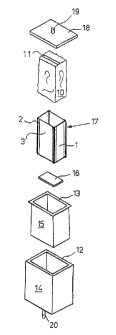
exploded view of Fig. 3. Starting at. the bottom, Fig. 3 shows
a box-shaped chamber 14 comprising a rigid bottom and rigid
walls. Mounted on the bottom is a connection stub 20 which
communicates via an aperture in the bottom with the interior
of the chamber. The stub 20 can be connected either to a
source of compressed air or a source of vacuum. Shown above
the chamber 14 is a bag-shaped body 15. The bag 15 comprises a
bottom and sidewalls of thin-walled flexible material, for
instance rubber foil, having a rigid flanged projecting edge
13 extending along the top edge 12. The shape and dimensions
~l ?l' ~~ ~ v~ ~~ e~
of the rubber bag 15 are such that the bag fits into the
chamber 14 with slight clearance, the edge 13 coming to rest
on the top edge 12 of the chamber. Shown above the bag 15 is a
holder 17 with associated loose bottom plate 16. The holder
5 comprises narrow plate-shaped flat sidewalls 1 and wide plate
shaped flat sidewalls 3 which are interconnected via spring
connection members 2 for relative movement (see also
Figs 4-&). Optionally, the loose bottom 16 can be connected to
the sidewalls of the holder in a similar manner by rneans of
10 spring members. In the inoperative position of the holder, the
inner shape thereof largely corresponds to the outside
dimensions of the vacuum-package 10 to be processed. The
inside dimensions of the holder, however, are greater than the
corresponding outside dimensions of the package, so that the
package can be arranged in the holder with a slight roundabout
clearance between the sidewalls of the holder and the package.
The holder 17 with bottom l6 fits into the bag 15. After the
package 10, the holder 17 with bottom 16, and the bag 15 have
been arranged in the chamber, the chamber can be closed
hermetically with a closing plate or cover 18 fitted with a
connection stub 19 which can be connected to a source of
vacuum.
The operation of the apparatus will now be explained with
reference to Figs 3 and 5. First, the apparatus is made ready
25' for operation by arranging the bag 15 with holder 1'? and
bottom 16 in the chamber 14. The package to be processed is
arranged in the holder and the chamber is closed by means of
~~~~~~~J
11
the cover 18, with the top edge 13 of the bag 15 being
hermetically clamped between the top edge 12 of the chamber
and the underside of the cover 18. When the cover has been
arranged on the chamber, some clearance remains present
between the top of the package and the flat underside of the
cover. Then the connection stub 20 is connected to a vacuum
pump, so that vacuum is applied to the closed space between
the inner wall of the chamber and the exterior of the bag. As
a result, the bag will come to rest against the inner walls of
the chamber. In this condition, the bag will be unable to
exert any pressure on the holder arranged therein, so that the
holder assumes the inoperative position. This is the situation
as shown in Fig. 5A. The connection stub 19 on the cover is
now connected to a vacuum pump, so that the space within the
bag, including the slit-shaped space 4 between the holder and
the package, is vacuumized, i.e., down to a pressure lower
than the pressure in the vacuum-package. The package will
thereby swell and the pressure within the package will
decrease as a result of the increase of volume thereof. When
the pressure in the space 4 between package and holder has
been lowered sufficiently, the package will expand to such an
extent that the packaging foil comes to rest against the
sidewalls and the bottom of the holder and the underside of
the cover. When the package swells, the packaging foil is
straightened, so that the unevennesses thereof will dj.sappear
for the greater part or completely. This situation is shown in
Fig. 5B.
~~~3~
12
Then, via connection 20, compressed air of for instance 5
bar gauge pressure is supplied to the space between the bag
and the chamber. As a result, the bag is pressed firmly
against the holder, so that the mutually movable walls of the
holder move towards each other and are pressed against the
package. At the same time, the bottom of the holder is pushed
up by the bag, so that the package is pressed against the
underside of the cover. During this movement of the holder, an
excess pressure relative to the external pressure continues to
prevail in the package, so that the foil remains pressed
tightly against the holder. While the package is being
subjected to pressure exerted by the holder and is optionally
compressed, it acquires the desired rectangular shape which is
determined by the walls of the holder including the bottom
thereof and the cover 1B. The parts of the packaging foil that
have become °'redundant" as a result of the straightening of
the foil collect in the corners of the package in the form of
projecting fins 6 (Fig. 5C, where the fins are shown on a
larger scale for clarity).
While the holder is still exerting pressure on the
package, the connection l9 on the cover is made to communicate
with the outside air. The foil remains pressed tight and
unwrinkled against the contents of the package. Then the
connection 20 zs also brought into communication with the
atmosphere, so that the holder can spring back into its
inoperative position (Fig. 5D). Although the package now sits
free within the holder, the package remains smooth on account
iJ ~2.~ ~ r,~ ~~ rl
13
of the atmospheric pressure. The chamber can now be opened by
removing the cover and the processed package can be taken from
the holder.
Optionally, during the operation, the package can at the
same time be checked for leakage. Two methods are available
for this purpose. According to the first method, the space 4
is closed off while it is still under vacuum and the holder
still retains the package in pressed condition (Fig. 5C).
Connection 19 is then connected to a pressure gauge which
measures the course of the pressure as a function of time for
a predetermined time. Since the pressure in space 4 is lower
than that in the package, the pressure in space 4 will rise if
the package leaks, while such a pressure increase will not
occur in a package that does not leak. According to the second
method, the space 4 between package and holder, with the
holder being maintained in its pressing condition, is not
closed off until after the space 4 has been brought into
communication with the atmosphere. As in the first method, the
course of the pressure in space 4 is then measured for a given
time. Since the pressure externally of the package is now
higher than that within the package, a leak in the package
will now manifest itself through a pressure drop in the space
4.
The operation according to the invention can also be
performed simultaneously on more than one package. Thus, Fig.
6 shows a combination 9 of four holders which are coupled to
each other by means of non-compressible intermediate pieces 7,
1~ ~' rd .~J ~ ;~j
14
8. This combination is arranged in a common bag basical7.y
corresponding to bag 15 and in a common chamber With cover,
basically corresponding to the chamber 14 and cover 18. In
this case, the four packages in the combination are processed
simultaneously.