Note: Descriptions are shown in the official language in which they were submitted.
~~~"~~.
FIEER ATTACHME3~TT MEANS FOR INTEGRATED OPTICAIa COMPOZdEPIT
The present invention relates to an integrated optical
component comprising at least one waveguide integrated into
a substrate and coupled to the end of a single mode or
multimode optical fiber. More specifically, the invention
relates to such a component in which the fibex is glued to
the substrate on the one hand a~t the fiber end which faces
an output of the integrated waveguide and on the other hand
at a location distant from this output.
HACICGROUIdD OF THE I13~1EI3TIOl~T
Such integrated optical components are known, for
example in Dannoux et al. U.S. patent No. 4,943,130 filed 12
March 1987 and assigned to Corning Glass Works: Conforming
to the preliminary specifications of specification T.W:NWT
000442 published in November 1990 by Bellcore (USA), such
optical components must pass predetermined tests which
assure the mechanical strength of the fiber/substrate
attachment and the transmission quality of an optica l
signal. The mechanical strength is tested by a pulling
force whACh is exerted upon the fiber/sub~trate attachment,
and the attachment must resist a force of 5N across the
temperature range from -40°C to x-85°C, or, further, in an
atmosphere of 93~ relative humidity at 60°C, or, further,
during aging for 2000 hours at 8a°C. Moreover, the excess
signal loss observed for a transmitted optical signal must
not exceed a predetermined threshold, for example, 0.8 dB
for a component with one input and two outputs.
With the integrated optical components which are cited
above one encounters a problem which is related to the
different thermal expansions of the materials forming the
substrate, the optical fibers and the adhesives of the
assembly. The substrate is readily made of a glass which
has a coefficient of thermal expansion on the order of
80x10°~ K°1. The integrated optical waveguide is farmed in
this glass by photolithographic mashing and ion exchange,
for example. The optical fiber, either single mode or
multimode, comprises very pure silica and doped silica which
have a coefficient of thermal expansion which is less than 6
x 10"~ K°~-, for example. Thus, for the same temperature
increase, the substrate is expanded more than the fiber,
which fiber is attached to the substrate at two separated
points. The substrate therefore exerts a tensile stress on
the section of the fiber situated between these two points.
This tensile force may generate a fiber fracture, a change
in the aptical properties of the silica which comprises the
fiber, or a deterioration of the fiber attachment points.
The coefficients of thermal expansion of the adhesive
products used may also play an important role in the
differential expansions which have been observed. Such
phenomena can alter, and in some cases even destroy the
optical continuity of the attachment between the fiber and
the waveguide of the integrated optical component, and thus
result in a concomitawt alteration or even a complete loss
of an optical signal transmitted across this attachment.
Other causes of alteration of the attachment are the effects
of environment, notably in humid atmosphere, and the aging
of the materials comprising the component, especially in the
event of excursions to decreasing temperatures, from ambient
temperature toward low temperatures (-40°C for example).
The present invention has therefore as its aim the
manufacture of an integrated optical component of the type
described above and designed tA insure satisfactory
mechanical and optical characteristics across a
predetermined wide range of temperature.
The present invention has also as its aim the
manufacture of such a component having a satisfactory
resistance to the effects of a high humidity atmosphere, and
to the effects of aging:
BUMMAFi3t OF' '.L'~iE T1~VLNTIODT
These objects of our invention, as well as others which
will be apparent from the present description, are achieved
by an integrated optical component designed for use in a
predetermined temperature range and comprising at least one
integrated optical waveguide formed in a substrate and
Coupled at an output to an optical fiber attached to the
substrate at that output and in a region separated
therefrom, by at least first and second drops of adhesive
product, respectively. The adhesive products constituting
these drops each have a glass transition temperature. Tn
accordance with the present invention, the glass transition
temperature of the first drop of adhesive product is within
the predetermined temperature range, and the glass
transition temperature of the second drop is in a second
temperature range. situated generally above the predetermined
range, the lower limit of the second range being -~/- 10°C
of the upper limit of the predetermined range.
Thus, the mechanical strength of the fiber/substrate
attachment is improved so that the differential expansion
will riot result in deterioration of the fiber or alter the
optical continuity of the fiber/waveguide attachment.
according to wn alternative embodiment of manufacturing
the integrated optical component in accordance with the
present invention, a third drop of adhesive product is
placed further away from the fiber endface than the second
drop, in order to secure the fiber to the substrate, the
glass transition temperature of the third drop being
generally above the predetermined temperature range. As
will be described below, one can thus diminish the volume of
adhesive product utilized and the influence that swelling of
these products in a humid environment exerts upon the
optical quality of the fiber/waveguide attachment.
to
According to yet another method of manufacturing the
integrated optical component in accordance with the present
invention, a fourth drop of adhesive product is used to
attach to the substrate the section of the fiber situated
between the second and third drops, the glass transition
temperature of this adhesive product being within the
predetermined temperature range. As will be explained in
the following portion of the present description, one thus
increases the strength of the section of the optical fiber
which is situated between the second and third drops of
adhesive product.
Other characteristics and advantages of the present
invention will appear upon reading the following
description, and upon examination of the attached FIGs.
~3RIEF DESGRIETION OF' THE DRAWINGS
FIG. ~. depicts a partial longitudinal cross-section of
an integrated optical component according to the invention,
showing the attachment between the fiber and a waveguide
integrated in the substrate, and the attachment between
between the fiber and the component substrate.
FIG. 2 depicts a cross-section similar to that of
FIG.1., of a second embodiment of the integrated optical
component according to the present invention.
CA 02062571 2002-06-21
- 5 -
FIG. 3 depicts a cross-section similar to those of
FIGS. 1 and 2, of a third embodiment of, the integrated
optical component according to the present invention.
FIG. 4 depicts a cross-section similar to those of
FIGS. 1 - 3, of a fourth embodiment of the integrated
optical component according to the present invention.
DETAILED DESCRIPTION
We refer now to FIG..1 showing the integrated optical
component according to the invention comprising a substrate
1, for example, formed of glass, and an optical fiber 2
which is protected by a coated portion 3. The fiber 2 is
partially stripped and rests upon a step 4 which is formed
upon the substrate in such away that its endface may be
coupled with the output of a waveguide 5 formed in the
substrate by an ion exchange technique, for example. .In
accordance with the design and process set forth in the
previously cited Dannoux et al. U.5. patent 4,943,130,a
transverse exit groove 6 (of 1 to 2mm width, for example)
can be provided for between step 4 and the junction of fiber
2 with the output of waveguide 5. This mechanical and
optical junction is assured by .a. first drop 7 of an adhesive
product having a suitable optical quality. This first drop
preferably has a small volume. A second drop 8 of the
adhesive product, having a greater volume, is placed upon
the fiber.and the substrate, to attach the fiber to the
substrate. As shown ~n FIG. 1, drop 8 covers both a
stripped portion and a coated portion of said optical
..
fiber. The second drop is separated~from the first by
transverse exit groove 6. These features of the
manufacturing process for the component in accordance with
the invention are described in detail in the previously
cited nannoux et al. U.S. patent 4,43,130.
As is now apparent, the attachment between the fiber
and the substrate is necessary at two points separated from
one another. As explained above, differential thermal
expansions are susceptible to causing mechanical stresses
which can deteriorate the attachment.
When these stresses reach certain thresholds, one
observes either a break in the optical continuity of the
fiber/waveguide attachment at drop 7, a break of the fiber,
or a modification of its optical properties. All of thsse
phenomena can seriously affect both the mechanical strength
of the fiber/substrate attachment, and the transmission of
an optical signal between fiber 2 and waveguide 5, through
the partial or total attenuation of this signal.
According ~o the present invention these problems are
avoided by utilizing, in order to create drop 7, an adhesive
product which has in its dry state a glass transition
temperature Tg within the predetermined operating
temperature range for the component (for example -40° to
+85°C as indicated above). When, within 'this temperature
range, the temperature of the drop in question rises above
~5 the Tg of the drop, the adhesive product of which 'the drop
is comprised passes into a visco-elastic phase. The
flexible attachment thus established between the fiber and
the substrate by the adhesive product in this phase, allows
a slight creeping of the fiber within the drop under the
effect of the differential thermal expansions which have
been observed. This creeping prevents the stresses which
are exerted upon the fiber from reaching the thresholds
which are capable of affecting its integrity or the optical
continuity of the fiber/waveguide attachment.
Tn the choice of the adhesive product which constitutes
_z_
drop 7, one must also take into account the optical
qualities of the product, in such a way as nod to alter
perceptibly an optical signal in its passage between the
fiber endface and the integrated waveguide output. In all
cases, the temperature Tg of the product within the
temperature range under consideration must be chosen so that
differential expansion occurring below this temperature Tg
does not perceptibly affect the structure or the function of
the integrated optical component in accordance with the
invention.
At the same time, one utilizes in the making of drop 8
an adhesive product whose glass transition temperature is
located within a second temperature .range situated generally
above the predetermined domain, the lower limit of the
second range being +/- 10°C of the upper limit of the
predetermined operating temperature range ("generally above"
said temperature range).
zo
Thus, the stability of the mechanical attachment
between the fiber and the support, over the entire
temperature range under consideration, rests upon the
adhesive of drop 8, in particular at the upper limit of this
range.
z5
The adhesive product chosen for drop 7 has a glass
transition temperature Tg located within the operating
temperature range, to insure the absorption of differential
expansions which would be dangerous for the component, and
30 the optical continuity of the fiber/waveguide attachment.
Tt is understood that it is necessary to choose far drop 7 a
transparent adhesive product which has an index of
refraction close to that of glass, that is to say close to
1.5.
An integrated optical component thus constructed in
_ g _
accordance with the invention permits the satisfaction of
conditions set forth by the above-mentioned preliminary
standard, notably in the matter of the strength of the
fiber/substrate attachment, under a tensile force carried at
+85°C. We have observed, however, certain difficulties in
satisfying the conditions set forth by this preliminary
standard with respect to operation in a humid atmosphere.
We have represented in FIG. 2 another method of
manufadturing the integrated optical component in accordance
with the invention, modified in order to overcome this
problem. In this figure, as in FIGS. 3 and 4, the numerical
references which are the same as those used in FIG. 1
correspond to identical or similar elements. The method of
manufacture of FIG. 2 is distinguished from that of FIG. 1
in that it comprises a thin drop 8 of adhesive product
placed upon fiber 2 at the edge of step 4, this drop being
made of an adhesive product having a glass transition
temperature located above the temperature range under
consideration. This drop 8 is itse3.f covered and overlapped
by an overlapping drop 9 of an adhesive product for which
the temperature of glass transition is within said
temperature range. Drop 8 assures the mechanical integrity
of the attachment between the fiber and the substrate
throughout the temperature range. Drop g protects drop 8
and fiber 2 against mechanical aggressions and against the
potential humidity of the ambient atmosphere. As shown in
FIG. 2, overlapping drop 9 reinforces the attachment
established by drop 8 between the substrate and the fiber,
and covers drop 8 and adjacent regions of the stripped and
coated portions of optical fiber 2. In the embodiment of
the present invention depicted in FIG. 2, drop 8 covers only
a stripped portion of the optical fiber and riot the coated
portion of the optical fiber, whereas drop 9 overlaps a
region of the coated portion. In accordance with this
manufacturing method, the functions of mechanical attachment
and optical continuity are separated. The mechanical
attachment is assured by drop 8 and, secondarily, by drop 9,
whereas the optical continuity is assured by drop 7.
Generally, as the differential thermal expansions are
principally absorbed by drop 7, it is advantageous to
arrange, during mounting, a space of approximately l5 to 25
~Cm, preferably 18 to 20 ~Cm, between the fiber endface and
the waveguide output in the substrate, thereby allowing a
clearance between the fiber and the waveguide.
An optical component made in conformity with FIG. 2 has
enabled the satisfaction of all the conditions set forth by
the above--referenced preliminary standard. We have
observed, however, that in an atmosphere of high humidity,
the swelling of drop 9 under the effect of this humidity may
provoke the bowing of the optical fiber 2 above transverse
exit groove 6. This bowing has the effect of misaligning
the fiber with respect to the waveguide, with a
corresponding attenuation of the transmitted optical signal.
In accordance with the invention, we reduce or prevent
such a bowing with: an integrated optical component made as
represented in FIG. 3. Drop 8 of the component represented
in FIG. 2 is divided, in the component of FIG. 3, into two
drops 8' and 8 " , set apart from one another, drop 8'
attaching the stripped portion of the fiber to step 4 of the
substrate while drop 8 " is placed at the unstrapped coated
portion 3 of fiber 2. The adhesive product used for both
drops has a glass transition temperature Tg situated
generally above the operating temperature range for the
component. The combined volume of the two drops 8' and 8 "
is substantially less than that of drop 9 in FIG. 2. The
bowing of the fiber due to the swelling of drop 9 by
molecules of water is thereby reduced to a significant
extent. The behavior of the component in a humid
environment is thereby improved. The effects of fiber
- io -
bowing at its end, due to the swelling of the adhesive, no
longer generate unacceptable misalignment of the fiber with
respect to the waveguide.
As indicated in FIG. 3, a transverse groove 10
separates drops 8' and 8 " . The intersection of the
surfaces at the edge of this transverse groove, by means of
surface tension, prevent the outflow of drops 8' and 8"
which thus remain well separated by groove 10.
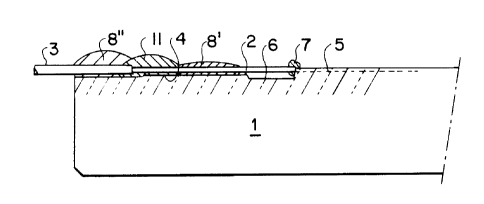
A variant of the embodiment of FIG. 3 is represented in
FIG. ~. According to this variant, the space separating
drops 8" and 8" (of an adhesive with a glass transition
temperature Tg situated generally above the operating
temperature range of the component), is occupied by a drop
11 of an adhesive having a glass transition temperature
located within this temperature range. This drop 11
improves the mechanical behavior of the fiber/substrate
attachment. It is necessary to consider the fact that, in
the embodiment of FIG: 3, the two drops 8' and 8 " of the
adhesive having a glass transition temperature located
generally above the operating temperature range of the
component, define bonding points which are fixed throughout
the operating temperature range. Due to the differential
thermal expansions when the temperature increases in the
temperature range under consideration, a growing tension is
exerted within the fiber between drops 8' and 8 " , even
though this tension would be limited by the presence of
coated portion 3 between drop 8 " and fiber 2. The
intervening drop 1Z of the embodiment of FIG. 4 strengthens
the resistance of the fiber to this tension, thereby
improving the mechanical behavior of the assembly.
In practice, the assembly of fiber 2 and the substrate
in the embodiment of FTG. 3 takes place as follows. The
fiber and the substrate are first assembled with the aid of
- 11 -
the deposit of drop 11, drops 8' and 8 " being placed
thereupon, drop 8' presenting as law a height as possible,
as is represented in FIG. 4. Fiber 2 and the output of
waveguide 5 are connected by a drop of glue 7, as carried
out in the preceding embodiments.
Adhesive products which are suitable for the present
invention and which have glass transition temperatures
characterized as indicated above, by virtue of their
position in the operating temperature range or generally
above this range, can be chosen by one skilled in 'the art
from numerous adhesive products which are readily available,
as a function of the particular application targeted and the
optical characteristics which will be eventually required of
this product. It is known, in this regard, that below their
glass transition temperature the adhesive products are
solid, whereas above this temperature they are soft, and
this effect increases as the temperature deviates from their
glass transition temperature Tg. The same is true of their
thermal coefficient of expansion, which has a more important
value above temperature Tg than below that temperature.
The glass transition temperature is a characteristic of
each adhesive which can be measured by differential thermal
analysis or by differential calorimetry by scanning a dry
product with a temperature slope of 5 to 10°C.per minute,
with heat starting at a temperature which is situated below
the transition temperature Tg. One can refer in this matter
to the work of R.C. McKenzie entitled ''Differential Thermal
Analysis'°, Volume 2, page 392., edited by the Academic
Press, and to the article by L. Monnerie which appeared in
the publication "Annales des Composites", pages 157 ff. of
the edition devoted to the conference of the Society of
Technical Analysis and Characterization of Macro--molecu7.ar
Materials, which was held in Paris in ~.98G.
- ~.2 -
Adhesive products made of acrylic or vinyl resin with
free radical polymerization are particularly suitable.
Therefore one can use advantageously for this effect,
monomers or oligomers of the acrylic or vinyl type
containing one or more double bonds, which give rise to free
radical polymerizations initiated by a photoinitiator which,
under the action of light (visible or ultra-violet, for
example) will create free radicals.
Optionally, one can utilize such resins with an
inorganic filler made of a silica powc'ier, or a hard organic
material, for example, in order to diminish the sensitivity
of the adhesive products to humidity; except, of course, for
the drop insuring the fiberjwaveguide attachment, which must
have a good transparency.
The choice of a particular resin, as we have seen
earlier, i.s a function of the location of its glass
transition temperature, within the operating range and
thereabove. In this respect one must take into account the
variation of this glass transition temperature as a function
of the humidity experienced by the resin, as well as the
variation of its coefficient of expansion and its Youngs
Modulus in the visco-elastic state, as a function of this
humidity. The choices to be made as based on these
considerations are within the normal skill of one skilled in
the art.
Numerous commercially available resins are suitable for
making the adhesive products which are used in the present
invention.
Thus, adhesive resins having a glass transition
temperature Tg within the range of temperature [-40°, +85°C]
which is specified above only as an example, are
commercialized by the Elosor Ltd. Corporation under the
- 13 -
trade name Vitralit 6128 (with Tg = 55°C), or Vitralit 7101,
7105 and 7106.
Adhesives with a glass transition temperature located
above this range of temperature are commercialized by the
French Corporation EPOTECHNY under the trade names NOA 81
(Tg = 120°C} or NOA 61 (Tg = 130°C)a and by the English
Corporation Imperial Chemical Industries under the trade
names LCR 000 and LCR 070 (Tg = 106°C or 117°C, according to
the hardening process used), LCR 050 (Tg = 106°}, LCR 000V
(Tg = 100°C), LCR 000/1.52 (Tg = 100°C).
Of course the present invention is not limited to the
man~zfacturing processes described and represented herein
which are given only as examples, similar to the preliminary
standard cited earlier. The invention extends to all
integrated optical components, multiplexing cauplers,
amp2ifiers, etc., connected to one or more optical fibers by
adhesives, and especially with respect to those adhesives
which are capable of passing into a visco-elastic phase in
order to permit the absorption without damage by the
component of differential expansions which manifest
themselves among the diverse elements of the component. The
invention is not limited to components which contain a glass
substrate in which one or several waveguides are integrated
by ion exchange. The invention extends, on the contrary, to
components in which this substrate comprises, for example,
silica or silicon having waveguides integrated by vapor
phase deposition, and to substrates of lithium niobate or
indium phosphide.