Note: Descriptions are shown in the official language in which they were submitted.
1 BACKGROUND OF THE INVENTION AND RELATED ART STATEMENT
The present invention relates to a method for
controlling an engine for driving a hydraulic pump which
generates pressurized fluid to drive a hydraulic
actuator for a construction equipment and, more
particularly, to a method for controlling an engine
wherein the number of revolutions (rotational speed) of
the engine is controlled in accordance with operating
conditions of a hydraulic pump for a hydraulic actuator
used in a construction equipment.
In a conventional method of controlling an
engine for driving a hydraulic pump which generates
hydraulic pressure to drive hydraulic actuators for
construction equipment and when it is sensed that an
operating lever by which an operator manipulates the
hydraulic actuators occupies a position for stopping
operations of all the hydraulic actuators over a
certain period of time, the number of revolutions of
the engine is reduced to less than the revolution
number of the engine during normal operation. After
the revolution number of the engine is thus reduced,
when the operating
2062591
1 lever is displaced from the position for stopping the
operations of the hydraulic actuators, in order to drive
at least one hydraulic actuators, the displacement of
the operating lever is sensed so that the revolution
number of the engine returns to the revolution number
for the normal operation. In this conventional method,
the control of the engine revolution number is performed
only on the basis of the position of the operating lever
handled by the operator.
10 OBJECT AND SUMMARY OF THE lNv~:N-lION
An object of the present invention is to
provide a method for controlling an engine for driving a
hydraulic pump to supply a pressurized fluid to a
hydraulic actuator in a construction equipment without
an unnecessary output of the engine and an inappropriate
output increase or insufficiency of the engine.
According to the present invention, a method
for controlling an engine for driving a hydraulic pump
to supply a pressurized fluid to a hydraulic actuator in
a construction equipment, comprises the steps of:
engine output decreasing step for decreasing a
fuel flow supplied to the engine so that an output
rotational speed of the engine is decreased to prevent
an excess output of the engine, and
engine output increasing step for increasing
the fuel flow to increase the output rotational speed of
2062591
1 the engine when a load of the engine for driving the
hydraulic pump is more than a first degree after the
engine output decreasing step.
Since the fuel flow is increased to increase
the output rotational speed of the engine when the load
of the engine for driving the hydraulic pump is more
than the first degree after the output rotational speed
of the engine is decreased to prevent the excess output
of the engine in the engine output decreasing step
in the present claimed invention, the fuel flow is
increased according to an actual condition of the load
of the engine so that the inappropriate output increase
is securely prevented when the fuel flow is kept small
to prevent the unnecessary output of the engine and the
inappropriate output in sufficiency of the engine is
securely prevented when a large output of the engine is
needed to operate the actuator.
BRIEF DESCRIPTION OF THE DRAWINGS
Fig. 1 is a schematic view showing an actuator
driving/controlling system in construction equipment to
which system one embodiment of the present invention is
applied;
Figs 2A and 2B are views illustrating a part
of a flowchart of a first embodiment of a method for
controlling a hydraulic pump driving engine according to
the invention;
2062591
1 Fig. 3 is a view illustrating another part of
the flowchart of the first embodiment;
Figs. 4A and 4B are views illustrating another
part of the flowchart of the first embodiment;
Fig. 5 is a view illustrating another part of
the flowchart of the first embodiment;
Fig. 6 is a diagram for explanation of
one embodiment of the controlling method for the
hydraulic pump driving engine according to the
invention;
Figs. 7A and 7B are views showing a part of a
flowchart of a second embodiment of the method for
controlling a hydraulic pump driving engine according to
the invention; and
Figs. 8A and 8B are views depicting another
part of the flowchart of the second embodiment.
DETAILED DESCRIPTION OF THE PREFERRED EMBODIMENTS
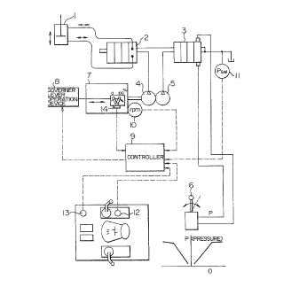
Fig. l shows an actuator driving/controlling
apparatus for a construction equipment to which
apparatus the present invention is applied. Though
there are normally provided a plurality of actuators 1
in the construction equipment, one of them is shown in
Fig. l, as a matter of convenience for clarifying the
invention. An operation of the actuator l is controlled
by a high-pressure hydraulic valve 2 which controls a
flow rate of high hydraulic pressure output from a high-
pressure hydraulic pump 4 to the actuator l and/or a
2062591
1 flow rate of hydraulic pressure from the actuator 1.
An operation of the high-pressure hydraulic valve 2 is
controlled by low hydraulic pressure which is output
from a low-pressure hydraulic pump 5 controlled by a
pilot valve 3, the output hydraulic pressure from the
low-pressure hydraulic pump 5 is generally in proportion
to an inclination angle ~ of an operation lever 6 with
respect to its upright position. Accordingly, the
operation of the actuator 1 is controlled, through the
pilot valve 3 and the high-pressure hydraulic valve 2,
by the operating lever 6 handled by the operator. In
general, the actuator 1 is arranged to stop the
operation thereof when the inclination angle ~ of the
operating lever 6 is zero.
The high-pressure hydraulic pump 4 and the
low-pressure hydraulic pump 5 are driven by an engine 7
including a governer 7 (not shown). The number of
revolutions (rotational speed) of the engine 7 is
adjusted on the basis of a fuel supplying rate which is
controlled by a governer lever operation device 8 for
moving a governer lever (not shown) of the governer 7.
The supplying rate of the fuel is regulated in accord-
ance with a position of the governer lever controlled
by the governer lever operation device 8. The position
25 of the governer lever controlled by the governer lever
operation device 8 is determined by a controller 9,
depending on the following factors: an output of a
revolution number detector 10 for measuring an output
2~D62591
1 revolution number of the engine 7; an output of a
pressure gauge 11 whieh measures the hydraulie pressure
applied to the pilot valve 3 in proportion to the opera-
tion inelination angle a of the operating lever 6 so as
to detect a faet that a eommand for stopping the opera-
tion of the aetuator 1 is issued or that a eommand for
operating the aetuator 1 is issued; an output of an
aeeel setting deviee 12 for setting a predetermined
revolution number of the engine 7 (a revolution number
of the engine 7 desirable when the engine rotates with-
out a redueed fuel supplying rate eaused by a speed-
reduetion eommand aeeording to the invention and with no
load, in other words, a revolution number whieh serves
as a referenee desired for the engine 7 under the eondi-
tion with no load, before the fuel supplying rate isdeereased or when it is not deereased, in aecordance
with a eondition of the engine load or a state of an
aetuator operating command); and an output from an AEC
setting device for eommanding an AEC (automatie engine
revolution number adjusting eontrol) operation at a
primary stage in whieh a deereasing degree of the engine
revolution number in response to the eondition of the
engine or the engine eondition eommand is small and at a
seeondary stage in whieh the decreasing degree of the
25 engine revolution number in response to the eondition of
the engine or the engine eondition eommand is large.
The load of the engine 7 for driving the hydraulie pumps
4 and 5 is measured from a differenee between an aetual
-- 6 --
2062591
1 output rotational speed of the engine 7 obtained when
the load is measured and an output rotational speed of
the engine 7 which is obtainable when the fuel flow
supplied to the engine 7 when the load is measured is
supplied to the engine 7 when an action of the actuator
1 is stopped.
A method of controlling the revolution number
(rotational speed) of the engine 7 by the fuel control
by means of the controller 9 via the governer lever
operation device 8 and the governer lever, accord-ing to
the present invention, will be described hereinafter.
Concrete examples of various kinds of set
values used in one embodiment of the invention, will be
listed below.
~ Predetermined Revolution : ACCEL = A desired revolution
Number speed of the engine with no
load at each accel position
~ Command Value of : NM1 = ACCEL - 100 rpm
Middle-speed Operation (at the AEC I stage)
: NM2 = ACCEL - 100 rpm
(at the AEC II stage)
~ C~m~nd Value of : NL1 = ACCEL - 100 rpm
Low-speed Operation (at the AEC I stage)
: NL2 - 1300 rpm
(at the AEC II stage)
~ Light-load Judging : Nll = Na - 10 rpm
2062~91
Revolution Number (at the AEC I stage)
: N21 = Na - 10 rpm
(at the AEC II stage)
~ Middle-load Judging : Nl2 = Na - 50 rpm
Revolution Number (at AEC I stage)
: N22 = Na - 50 rpm
(at the AEC II stage)
~ Heavy-load Judging Revolution Number
~ Judging Revolution Number for Returning During
Low-Speed Operation
: Nl3 = Na - 70 rpm
(at the AEC I stage)
: N23 = Na - 70 rpm
(at the AEC II stage)
~ Judging Revolution Number for Returning During
Middle-Speed Operation
: N14 = Na - 70 rpm
(at the AEC I stage)
: N24 = Na - 70 rpm
(at the AEC II stage)
~ No-load Revolution Number at Each Governer Lever
Position
: Na (This number changes in
accordance with each
governer lever position.)
1 [Na is the number of revolutions of the engine, at a
speed higher than which number of revolutions the engine
rotates when a rate of fuel in response to the position
-- 8 --
20~25gl
1 of the governer lever is supplied to the engine from the
governer, in the case where the engine revolves with no
load (the actuator is not operated). The value of Na is
calculated on the basis of a predetermined relation
between the governer lever position and the no-load
revolution number Na, in accordance with the governer
operated position measured by the governer lever
position detector 14, when measuring the load.]
~ Light-load Judging Time ; T1A = 3 seconds
(at the AEC I stage)
: T2A = 3 seconds
(at the AEC II stage)
~ Middle-load Judging Time : T18 = 10 seconds
(at the AEC I stage)
: ( T28 = 1 O seconds
(at the AEC II stage)
Next, there will be described a relation
between a load condition of the engine and the engine
controlling method on selection of the AEC I stage, in
the case where the various kinds of values are set in
the above-mentioned manner. A selected condition is
such that the operator selects the AEC I stage and a
full-accel position (ACcel = 2000 rpm) as a position of
the accel. When the AEC II stage is selected, each set
value is exchanged and a relation indicated below is
applied. Portions represented by alphabets correspond
to steps in flowcharts of Figs. 2A, 2B, 3, 4A, 4B and 5.
2062S9l
1 1. A relation between the load condition and the engine
controlling method on issue of the low speed operation
command
1) The load condition occurring when the
engine is brought into the light-load condition from the
heavy-load condition and the engine controlling method
[Table 1]
FLOW (i) START ~ A ~ B ~ C ~ D ~ E ~ F ~ J ~ K
~ O ~ P ~ START
(ii) START ~ A ~ B ~ C ~ D ~ E F ~ G ~ H
~ K ~ L ~ M P ~ START
(iii) START ~ A ~ B ~ C ~ D ~ E . ~ F ~ G ~ H
~ I ~ START
(iv) START ~ A ~ B ~ C ' D ~ Q ~ R ~ S ~ T
~ I ~ START
(v) START ~ A ~ B ~ C ~ D ~ E Q ~ R ~ S
START
(i) Heavy-load condition
Now, in a condition of the governer lever for
supplying fuel in order to perform a predetermined
rotation operation (the full-accel operation), the
engine actually rotates in the heavy-load condition with
the number Ne of revolutions of 1800 rpm. First,
various kinds of input signals are processed through the
A step and each predetermined value is set as follows.
-- 10 --
2062591
~ AEC SW = I stage
~ ACCEL = 2000 rpm
~ Ne = 1800 rpm
. Na = ACCEL = 2000 rpm
1 Because the AEC I stage is selected, a FLOW proceeds
from A to B, C and D where the respective values are
predetermined in the following manner.
~ Nll = Na - 10 rpm = ACCEL - 10 rpm = 1990 rpm
~ N12 = Na - 50 rpm = ACcEL - 50 rpm = 1950 rpm
~ N13 = Na - 70 rpm = ACCEL - 70 rpm = 1930 rpm
~ Nl4 = Na - 70 rpm = ACCEL - 70 rpm = 1930 rpm
The FLOW branches to YES at the operating condition
judging step E because the engine is desired to rotate
with the predetermined revolution number ACcEL. At the
light-load judging step F, the true (Ne ~ Nll) is not
achieved because Ne, which is 1800 rpm, is smaller than
Nll, which is 1990 rpm, so that the FLOW branches to NO.
A light-load elapsed time measuring counter is cleared
at the J step and Tll becomes zero. Further, at the
middle-load judging step K, Ne > Nl2 is not achieved
because Ne, which is 1800 rpm, is smaller than N12,
which is 1950 rpm, and the FLOW branches to NO. A
middle-load elapsed time measuring counter at 0 is
cleared so that T12 becomes zero. In this FLOW, the
operation reaches the predetermined rotation operation
2062591
1 command step P so as to achieve the desired predeter-
mined operation as indicated by the accel. The FLOW
returns to START again.
(ii) Light-load transition condition (before the number
of revolutions of the engine is lowered after the load
of the engine becomes small)
Here, the engine load condition changes from
the heavy-load condition into the light-load condition.
A no-load neutral condition is supposed as the light
load. An actual number of the engine revolutions
changes from 1800 rpm to 2000 rpm (the revolution number
of the engine rotating with no load). The FLOW proceeds
from A to B, C and D successively. Because the governer
lever has been retained at the predetermined position
yet, Na is equal to ACCEL which is 2000 rpm at A.
Therefore, the values of Nll, Nl2, Nl3, and N14 are not
changed, respectively, at D and the values in the FLOW
(i) are maintained.
Under the condition of the predetermined
operation at E, the FLOW branches to YES, similarly to
the foregoing FLOW. The direction of the FLOW changes
at the light-load judging step F. That is to say, since
Ne which is 2000 rpm is larger than Nll which is 1990
rpm, Ne > Nll is achieved and the FLOW branches to YES.
A light-load elapsed time measuring counter at
G counts up so that T12 becomes 0.02 seconds if one
count corresponds to 0.02 seconds. At the light-load
elapsed time judging step H, Tll which is 0.02 seconds
- 12 -
2062S9l
1 is smaller than T1A which is 3 seconds, and consequent-
1Y, T11 > T1A is not achieved and the FLOW branches
to NO.
At the middle-load judging step K, because Ne
which is 2000 rpm is larger than N12 which is 1950 rpm,
the FLOW branches to YES.
A middle-load elapsed time measuring counter
at L counts up so that T12 becomes 0.02 seconds from 0.
At the middle-load elapsed time judging step
M, T12 which is 0.02 seconds is smaller than T1B which
is 10 seconds, and therefore, T12 > T1B is not achieved.
The FLOW reaches P after it branches to NO. The
predetermined rotation (accel command) operation is
still directed and the AEC has not been operated yet.
(iii) Start of the low-speed operation command under
the light-load (neutral) condition (when a period of
time during which the engine load is small exceeds a
certain limit and the revolution number of the engine is
started to be lowered)
When the FLOW of the above paragraph (ii) is
generated continuously for 151 cycles, the low-speed
operation command is started.
This FLOW advances from A to B, C, D, E and up
to F, similarly to the FLOW of the paragraph (ii). At
the time of the 151 cycle, the light-load elapsed time
measuring counter G counts up so that Tll indicates 3.02
seconds.
- 13 -
2062~91
1 At the light-load elapsed time judging step H,
because Tll is 3. 02 seconds and T1A is 3 second and Tll
is larger than T1A~ T11 > T1A is achieved, and the FLOW
branches to YES. As a result, the low-speed operation
is commanded for the first time at I. (In addition, the
value of the middle-load elapsed time achieved at the
last 150th cycle is maintained so that T12 is 3.00
seconds.)
(iv) During transition to the position of the low-speed
operation under the light-load (neutral) condition (in
the process of lowering the revolution number of the
engine)
Here will be described such condition that the
governer lever receives the low-speed operation command
issued at the last FLOW (iii) firstly so as to move to
the low-speed position by means of the governer lever
operation device. As a concrete example, there is shown
a FLOW after the governer lever is driven to the
intermediate position between the predetermined speed
and the flow speed. First, at A, the value of Na is
changed differently from that of the above paragraph
(iii), because the governer lever is moved. As a matter
of convenience for explanation, if a relation between
the position of the governer lever and Na (the no-load
revolving speed) is linear, N = (ACCEL + NLI)/2 = (2000 +
1900 )/2 = 1950 rpm because the governer lever is moved
to the intermediate position thereof. (Note: Since the
relation is not always linear due to the governer and
- 14 -
2062591
1 engine characteristics in actual cases, the no-load
revolution number Na may be calculated through a
previously memorized function.) It is supposed that the
actual engine revolution number Ne under the no-load
condition is 1950 rpm. In this way, after Na is
renewed, the FLOW proceeds from B to C and D, and the
respective values are renewed by the load judging
revolution number setting step D as follows.
~ Nll = Na - 10 rpm = ACCEL - 10 rpm = 1940 rpm
~ Nl2 = Na - 50 rpm = ACCEL - 50 rpm = 1900 rpm
~ N13 = Na - 70 rpm = ACCEL - 70 rpm = 1880 rpm
~ Nl4 = Na - 70 rpm = ACCEL - 70 rpm = 1880 rpm
Now, because the low-speed operation is being commanded,
the FLOW branches to NO at the operating condition
judging step E, and then, the FLOW branches to YES at
the adjoining step Q.
Because Ne is 1950 rpm and N13 is 1880 rpm and
Ne is larger than N13 at the heavy-load judging step R,
Ne < N13 is not achieved and the FLOW branches to NO.
The FLOW branches to YES because it is measured by the
operating condition judging step S that the governer
lever is being displaced toward the low speed position
thereof. Further, at the light-load judging step T,
since Ne is 1950 rpm and Nll is 1940 rpm and Ne is
larger than Nll, Ne < Nll is achieved, the FLOW branches
to YES so that the low-speed operation command in which
2062591
~..
1 the governer lever is moved to the low speed position
gradually is continued at I.
(v) The low-speed operation under the light-load
(neutral) condition (when the low-speed operation
revolution number of the engine is maintained within a
desired range)
The FLOW under such condition that the
governer lever finally has reached the low-speed
operation position will be shown. Incidentally, Ne is~
1900 rpm.
Under such operating condition, the value of
Na at A is as follows.
Na = NL1 = ACcEL - 100 rpm = 2000 rpm - 100 rpm
= 1900 rpm
More specifically, Na becomes the low-speed operation
revolution number, and the FLOW advances from B to C and
D. The respective values are renewed at the load
judging revolution number setting step D in the
following manner.
~ Nll = Na - 10 rpm = 1900 rpm - 10 rpm = 1890 rpm
~ N12 = Na - 50 rpm = 1900 rpm - 50 rpm = 1850 rpm
~ N13 = Na - 70 rpm = 1900 rpm - 70 rpm = 1830 rpm
~ N14 = Na - 70 rpm = 1900 rpm - 70 rpm = 1830 rpm
- 16 -
2062S91
1 Because the low-speed operation is being
commanded at present, the FLOW branches to NO at the
operating condition judging step E, and it then branches
to YES at the subsequent Q step.
Since Ne is 1900 rpm and Nl3 is 1830 rpm and
Ne is larger than Nl3 at the heavy-load judging step R,
Ne < Nl3 is not achieved and the FLOW branches to NO.
The low-speed operation is performed so that the FLOW
branches to NO at the operating condition judging step S
and directly leads to I. Thus, the low-speed operation
is continued under the no-load condition.
2) Charging of a heavy load during the low-speed
operation with no load (when the heavy load is applied
to the engine which operates at low speed with
continuation of the no-load condition)
FLOW (v) START ~ A ~ B ~ C ~ D ~ E ~ Q ~ R ~ S
~ I ~ START
FLOW (vi) START ~ A ~ B ~ C ~ D -~ E ~ Q ~ R ~ P
~ START
(v) During the low-speed operation with no load (when a
rate of fuel which is enough to perform the low-speed
operation at a generally desired low revolving speed, is
being applied to the engine)
It is assumed that the above-mentioned low-
speed operation with no load is continued.
- 2062591
1 The FLOW is quite similar to the FLOW (v) of
the paragraph 1. - 1). The respective constants and
variables are as follows.
~ AEC SW = I stage
~ ACCEL = 2 O O O rpm
~ Ne = 1900 rpm
. Na = LL1 = 19 O O rpm
~ Nll = Na - 10 rpm = 1900 rpm - 10 rpm = 1890 rpm
~ N12 = Na - 50 rpm = 1900 rpm - 50 rpm = 1850 rpm
~ N13 = Na - 70 rpm = 1900 rpm - 70 rpm = 1830 rpm
~ N14 = Na - 70 rpm = 1900 rpm - 70 rpm = 1830 rpm
~ Nll = 3.0 2 seconds
~ N12 = 3.00 seconds
(vi) Charging of the heavy load (when the heavy load is
applied to the engine at the time of supplying to the
engine a rate of fuel which is enough to perform the
low-speed operation)
When such heavy load that the revolution
number Ne of the engine is made 1750 rpm is applied in
the last FLOW (v) (during the low-speed operation with
no load), the governer lever has been at the low-speed
operation position yet. Therefore, the respective
values are determined at A as follows.
~ AEC SW = I stage
~ ACCEL = 2000 rpm
- 18 -
20625gl
-
~ Ne = 1750 rpm
. Na = NL1 = 1900 rpm
1 Subsequently, the FLOW advances to B, C and D. The last
values are maintained at D.
. Nll = Na - 10 rpm = 1900 rpm - 10 rpm = 1890 rpm
. N12 = Na - 50 rpm = 1900 rpm - 50 rpm = 1850 rpm
~ N13 = Na - 70 rpm = 1900 rpm - 70 rpm = 1830 rpm
~ N14 = Na - 70 rpm = 1900 rpm - 70 rpm = 1830 rpm
Because the low-speed operation is being
commanded at present, the FLOW branches to NO at the
operating condition judging step E and branches to YES
at the subsequent Q step, the FLOW then leading to R.
At the heavy-load judging step R, Ne is 1750 rpm and N13
is 1830 rpm and Ne is smaller than N13 so that the true
(Ne < N13) is achieved. As a result, the FLOW branches
to YES.
If the heavy load is detected, the FLOW gets
to P without delay and the predetermined operation is
immediately commanded.
After commanding the predetermined rotating
operation, this FLOW becomes similar to the FLOW (i) at
the above-mentioned time when the heavy load is
supplied. However, the values of both Ne and Na are
renewed every time until the governer lever is returned
to the position of the predetermined rotation. Nll,
2062591
~.~.,
1 N12, N13 and N14 are also renewed, respeetively, in
response to the renewal of Na, and the load judging
conditions in F and K are renewed.
Meanwhile, the values of the light and middle
load elapsed times Tll and T12, which have been
maintained on the last oeeasion, are eleared to zero as
follows, at the point of time when the FLOW passes J and
O for the first time so that when the operation is .
performed under the light or middle load eondition, the
counters can start to count up from zero second.
~ Tll = 3.02 seeonds ~ 0 second
~ Tl2 = 3.00 seconds ~ 0 second
3) Charging the middle load during transition to the
low-speed operation (retaining movement) (when the
middle load which is larger than the light load but is
smaller than the heavy load is applied in the proeess of
decreasing the revolution number of the engine while the
engine load is so small that the no-load condition is
continued)
FLOW (iv) START ~ A ~ B ~ C ~ D ~ E ~ Q ~ R ~ S
~ T ~ I ~ START
(vii) START ~ A ~ B ~ C 1 D ~ E ~ Q ~ R ~ S
~T ~ U ~ START
- 20 -
20~2S9l
1 (iv) During transition to the position of the low-speed
operation under the light-load (neutral) condition (as
one example of state in the process of lowering the
revolution number of the engine, in the case where the
engine revolution number is between the predetermined
revolution number and the low-speed operation commanding
value)
Here, the FLOW proceeds quite similarly to the
above-described FLOW 1. - 1) - (iv). In other words,
the governer lever is also at the intermediate position
between the predetermined speed position and the low-
speed position. Accordingly, Ne is 1950 rpm and Na is
1950 rpm. The values of Ne and Na at D are also the
same.
~ Nll = Na - 10 rpm = 1950 rpm - 10 rpm = 1940 rpm
~ N12 = Na - 50 rpm = 1950 rpm - 50 rpm = 1900 rpm
~ N13 = Na - 70 rpm = 1950 rpm - 70 rpm = 1880 rpm
~ N14 = Na - 70 rpm = 1950 rpm - 70 rpm = 1880 rpm
(vii) Charging of the middle load (when the middle load
which is larger than the light load but smaller than the
heavy load is applied under the above-mentioned
condition)
It is supposed that the middle load is charged
in the last FLOW (iv) (during the transition to the
position of the low-speed operation) such that the
engine revolution number Ne is smaller than Nll and
2062~91
1 larger than N13.
Approximately 1920 rpm is obtained as a value
of the engine revolution number Ne.
The respective values at the input processing
unit A are set as follows.
. AEC SW = I stage
~ ACCEL = 2000 rpm
~ Ne = 1920 rpm
. Na = ACCEL = 1950 rpm
Subsequently, the FLOW advances to B, C and D. The
values of the last paragraph (iv) are maintained at D.
Because the low-speed operation is being
commanded at present, the FLOW branches to NO at the
operating condition judging step E and branches to YES
at the subse~uent Q step, the FLOW then leading to R.
At the heavy-load judging step R, Ne is 1920 rpm and N13
is 1880 rpm and Ne is larger than N13 so that the true
(Ne < N13) is not achieved. As a result, the FLOW
branches to No.
At the operating condition judging step S, the
FLOW branches to YES because the operation is being
changed to the low-speed operation. Further, at the
light-load judging step T, because Ne is 1920 rpm and
Nll is 1940 rpm and Ne is smaller than Nll, Ne > Nll is
not achieved so that the FLOW branches to NO, arriving
at the operating condition command step U. As a result,
- 22 -
2062591
1 a command for retaining the present position of the
governer lever is issued.
If the operation is brought into the no-load
condition again after this middle-load condition (that
is, the retained condition) is continued for a little
(for example, the engine revolution number Ne which has
been 1920 rpm returns to 1950 rpm), the FLOW becomes
similar to the FLOW (iv). At the light-load judging
step T, Ne which is 1950 rpm is larger than Nll which is
1940 rpm, and accordingly, Ne ~ Nll is achieved. The
operation command changes from the condition retaining
command to the low-speed operation command I without
delay so that the governer lever is moved to the
position of the low-speed operation.
A supplementary explanation concerning the
retaining function will be given here. The light-load
judging step T acts to branch the operation command into
the following two commands in association with the load
judgement at the previous heavy-load judging step R.
(a) Ne > Nll (the light load condition)
-- ~a command for performing the
low-speed operation
(b) Nll ~ Ne > N13 (the intermediate condition between
the heavy and light load
conditions)
-- ~ a command for retaining the
present position
- 23 -
2062~91
1 More specifically, in view of operatability of a
hydraulic shovel, because a certain load is charged
though the load is not so heavy that the engine
revolution number should return to the predetermined
revolution number (high speed), the present position of
the governer lever is retained without reducing the
revolving speed to be low.
2. A relation between the load condition and the engine
controlling method on issue of the middle-speed
operation command
l) The load condition achieved when the engine is
brought into the middle-load condition from the heavy-
load condition and the engine controlling method
[Table 2]
FLOW (i) START ~ A ~ B I C I D I E I F I J I K
~ O ~ P I START
(ii) START -~ A I B ~ C ~ D I E I F ' J ' K
~ L I M I P I START
(iii) START ~ A I B I C ~ D I E I F I J ~ K
~ L I M ~ N I START
( iv) START ~ A ' B I C I D ~ E I Q ~ V ~ W
~ X N ~ START
( v ) START ' A I B I C I D I E I Q I V I W
I N I START
(i) Heavy load condition
Similarly to the aforesaid FLOW 1. - 1) (i),
the engine operation is under such heavy-load condition
- 24 -
~ 2062591
1 that the engine revolution number Ne is about 1800 rpm.
The respective values are as follows, similarly to the
last FLOW (i), and the predetermined rotation operating
command is finally issued from P.
~ AEC SW = I stage
~ ACCEL = 2000 rpm
~ Ne = 1800 rpm
Na = ACCEL = 2000 rpm
~ Nll = Na - 10 rpm = ACCEL - 10 rpm = 1990 rpm
~ Nl2 = Na - 50 rpm = ACCEL - 50 rpm = 1950 rpm
~ Nl3 = Na - 70 rpm = ACCEL - 70 rpm = 1930 rpm
~ N14 = Na - 70 rpm = ACCEL - 70 rpm = 1930 rpm
~ Nll = 0 second
~ N12 = 0 second
(ii) Middle-load transition condition (before the
number of revolutions of the engine is lowered after the
load of the engine becomes small)
Here, the load condition changes from the
heavy-load condition to the middle-load condition.
About 1970 rpm is selected as a value of the revolution
number Ne of the engine rotating with the middle load.
The number Ne of the engine revolutions changes from
1800 rpm to 1970 rpm. The FLOW proceeds from A to B, C
and D, successively. Because the governer lever has
been retained at the predetermined position yet, Na is
equal to ACCEL which is 2000 rpm at A. Therefore, the
- 25 -
2062591
1 values of Nll, Nl2, N13 and Nl4 are not changed,
respectively, at D and the values in the FLOW (i) are
maintained.
Under the condition of the predetermined
operation at E, the FLOW branches to YES, similarly to
the foregoing FLOW. The FLOW changes at the light-load
judging step F. That is to say, since Ne which is 1970
rpm is smaller than Nll which is 1990 rpm, Ne ~ Nll is
not achieved and the FLOW branches to NO. In the light-
load elapsed time measuring counter step J, although thelast value Tll is zero, a clearing action is performed.
At the middle-load judging step K, because Ne
which is 1970 rpm is larger than N12 which is 1950 rpm,
the FLOW branches to YES.
A middle-load elapsed time measuring counter
at L counts up so that T12 becomes 0.02 seconds from 0.
At the middle-load elapsed time judging step
M, T12 which is 0.02 seconds is smaller than TIB which
is 10 seconds, and consequently, T12 ' T1B is achieved.
The FLOW reaches P after it branches to NO. The
predetermined rotation (accel command) operation is
still directed and the AEC has not been operated yet.
(iii) Start of the middle-speed operation command under
the middle-load condition (when a period of time during
25 which the engine load is small exceeds a certain limit
and the number of revolutions of the engine is lowered)
When the above-described FLOW (ii) is
continuously generated for 501 cycles, the middle-speed
- 26 -
2062591
1 operation command is started.
This FLOW advances from A to B, C, D, E, F, J
and up to K, similarly to the aforesaid FLOW (ii). At
the time of the 501 cycle, the middle-load elapsed time
measuring counter at L counts up so that T12 indicates
10.02 seconds. At the middle-load elapsed time judging
step M, because T12 which is 10.02 seconds is larger
than T1B which is 10 seconds, T12 ' T1B is achieved, and
the FLOW branches to YES. As a result, the middle-speed
operation is commanded for the first time at N. (In
addition, the value of the light-load elapsed time is
cleared to zero so that Tll becomes zero second.)
(iv) During transition to the position of the low-speed
operation under the middle-load condition (in the
process of lowering the number of the engine
revolutions)
Here will be described such condition that the
governer lever receives the middle-speed operation
command issued in the last FLOW (iii) for the first time
so as to move to the middle-speed position by means of
the governer lever driving device. As a concrete
example, there is shown the FLOW after the governer
lever is urged to the intermediate position between the
predetermined speed position and the low speed position.
First, at A, the value of Na is changed differently from
that of the above FLOW (iii), because the governer lever
is moved.
- 27 ~
2062591
1 As a matter of convenience for explanation, if
a relation between the position of the governer lever
and Na (the number of revolutions of the engine with no
load) is linear, N = (ACCEL + NM1)/2 = (2000 + 1900)/2 =
1950 rpm because the governer lever is at the
intermediate position. (Note: Since the relation is not
always linear due to the governer and engine
characteristics in actual cases, the no-load revolution
number Na may be calculated through a previously
memorized function.) It is supposed that the engine
revolution number Ne is 1920 rpm.
In this way, after Na is renewed, the FLOW
proceeds from B to C and D, and the respective values
are renewed by the load judging revolution number
setting step D as follows.
~ Nll = Na - 10 rpm = 1950 rpm - 10 rpm = 1940 rpm
~ N12 = Na - 50 rpm = 1950 rpm - 50 rpm = 1900 rpm
~ Nl3 = Na - 70 rpm = 1950 rpm - 70 rpm = 1880 rpm
~ N14 = Na - 70 rpm = 1950 rpm - 70 rpm = 1880 rpm
Now, because the middle-speed operation is being
commanded, the FLOW branches to NO at the operating
condition judging step E and the FLOW also branches to
YES at the adjoining step Q.
At the heavy-load judging step V, New which is
1920 rpm is larger than N14 which is 1880 rpm, and
therefore, Ne < Nl4 is not achieved and the FLOW
- 28 -
2062591
1 branches to NO. The FLOW branches to YES because it is
measured at the operating condition judging step W that
the governer lever is being displaced to the middle-
speed position. Further, at the middle-load judging
step X, since Ne of 1950 rpm is larger than N12 of 1940
rpm, Ne > Nll is achieved, and the FLOW branches to YES
so that the middle-speed operation command (te governer
lever should be moved to the middle speed position)
continues to be issued at N.
(v) The middle-speed operation under the middle-load
condition (when the number of the middle-speed
revolutions of the engine is maintained within a desired
range)
The FLOW achieved under such condition that
the governer lever finally reaches the middle-speed
operation position, will be shown. Incidentally, Ne is
set to be 1870 rpm.
Under this operating condition, the value of
Na at A is as follows.
Na = NM1 = ACCEL - 100 rpm = 2000 rpm - 100 rpm
= 1900 rpm
More specifically, Na becomes the revolution number of
the engine during the middle-speed operation, and the
FLOW advances from B to C and D. The respective values
are renewed at the load judging revolution number
setting step D in the following manner.
2062591
~ Nll = Na - 10 rpm = 1900 rpm - 10 rpm = 1890 rpm
~ N12 = Na - 50 rpm = 1900 rpm - 50 rpm = 1850 rpm
~ Nl3 = Na - 70 rpm = 1900 rpm - 70 rpm = 1830 rpm
~ N14 = Na - 70 rpm = 1900 rpm - 70 rpm = 1830 rpm
1 Because the middle-speed operation is being
commanded at present, the FLOW branches to NO at the
operating condition judging step E and it then branches
to NO at the subsequent Q step.
At the heavy-load judging step V, since Ne
which is 1870 rpm is larger than Nl4 which is 1830 rpm,
Ne < N14 is not achieved and the FLOW branches to NO.
The middle-speed operation is performed at the operating
condition judging step W so that the FLOW branches to NO
and directly leads to N.
Thus, the middle-speed operation is continued
under the middle-load condition.
2) Charging of the heavy load judging the middle-speed
operation with the middle load (when the heavy load is
applied to the engine in case of supplying to the engine
a rate of fuel for performing the middle-speed
operation)
FLOW (v) START ~ A ~ B ~ C ~ D ~ E ~ Q ~ V ~ W
~ N ~ START
(vi) START ~ A 1 B -~ C ~ D ~ E ~ Q ~ V P
START
- 30 -
2062591
1 (v) During the middle-speed operation with the middle
load (when a rate of fuel which is enough to perform the
middle-speed operation with the generally desired number
of the middle-speed revolutions, is being applied to the
engine)
It is assumed that the above-mentioned middle-
speed operating condition with the middle load is
continued. The FLOW is quite the same as the FLOW 2.
- 1) (v). The respective constants and variables are as
10 followS.
~ AEC SW = I stage
~ ACCEL = 2000 rpm
~ Ne = 1870 rpm
. Na = LL1 = 1900 rpm
~ Nll = Na - 10 rpm = 1900 rpm - 10 rpm = 1890 rpm
~ N12 = Na - 50 rpm = 1900 rpm - 50 rpm = 1850 rpm
~ N13 = Na - 70 rpm = 1900 rpm - 70 rpm = 1830 rpm
~ Nl4 = Na - 70 rpm = 1900 rpm - 70 rpm = 1830 rpm
~ Nll = 10.02 seconds
~ N12 = 0.00 second
(vi) Charging of the heavy load (when the heavy load is
applied to the engine during the middle-speed operation)
Such heavy load that the engine revolution
number Ne becomes 1750 rpm is charged in the last FLOW
(v) (during the middle-speed operation with the middle
load). The governer lever has been at the middle-speed
- 31 -
-2062591
1 operation position yet at the time of charging the load.
Therefore, the respective values at A are determined as
follows.
~ AEC SW = I stage
~ ACCEL = 2000 rpm
~ Ne = 1750 rpm
. Na = NM1 = 1900 rpm
Subsequently, the FLOW advances from B to C and D. The
last values at D are maintained.
~ Nll = Na - 10 rpm = 1900 rpm - 10 rpm = 1890 rpm
~ N12 = Na - 50 rpm = 1900 rpm - 50 rpm = 1850 rpm
~ N13 = Na - 70 rpm = 1900 rpm - 70 rpm = 1830 rpm
~ Nl4 = Na - 70 rpm = 1900 rpm - 70 rpm = 1830 rpm
Because the middle-speed operation is being commanded at
present, the FLOW branches to NO at the operating
condition judging step E and also branches to NO at the
subsequent Q step, the FLOW then léading to V. At the
heavy-load judging step V, Ne of 1750 rpm is smaller
than N14 of 1830 rpm so that the true (Ne < Nl4) is
achieved. AS a result, the FLOW branches to YES.
If the heavy load is detected, the FLOW gets
to P without delay and the predetermined operation is
immediately commanded.
- 32 -
~062591
1 After commanding the predetermined rotating
operation, this FLOW becomes similar to the above-
described FLOW (i) during charging the heavy load.
However, the values of both Ne and Na are renewed every
time until the governer lever is returned to the
position of the predetermined rotation. In response to
the renewal of Na, the values of Nll, Nl2, Nl3 and Nl4
are also renewed, respectively. The load judging
conditions of F and K are renewed.
Meanwhile, the values of the light and middle
load elapsed times Tll and Tl2, which have been
maintained on the last occasion, are cleared to zero as
follows, at the point of time when the FLOW passes J and
O for the first time. When the operation is performed
under the light or middle load condition, the counters
can start to count up from zero second.
~ Tll = 3.02 seconds ~ 0 second
~ Tl2 = 3.00 seconds ~ 0 second
3) Increase of the load during displacement of the
governer lever to the middle-speed operation position
(retaining movement) (in the case where the load larger
than the middle load is applied in the process of
lowering the engine revolution number to that of the
middle-speed operation when the engine load is small and
the middle-load condition is continued)
- 33 -
2062591
FLOW (iv) START ~ A ~ B ~ C ~ D ~ E ~ Q V ~ X
~ N ~ START
(vii) START ~ A ~ B ~ C ~ D ~ E ~ Q ~ V ~ X
~ U ~ START
1 (iv) During displacement of the governer lever to the
position of the middle-speed operation under the middle-
load condition (as one example of state in the process
of lowering the engine revolution number to that of the
middle-speed operation, in the case where the engine
revolution number is between the predetermined
revolution number and the middle-speed operation command
value)
Here, the FLOW proceeds quite similarly to the
above-described FLOW 2. - 1) - (iv). In other words,
the governer lever is also at the intermediate position
between the predetermined speed position and the low-
speed position. Accordingly, Ne is 1920 rpm and Na is
1950 rpm. The values of Ne and Na at D are also the
same.
~ Nll = Na - 10 rpm = 1950 rpm - 10 rpm = 1940 rpm
~ Nl2 = Na - 50 rpm = 1950 rpm - 50 rpm = 1900 rpm
~ N13 = Na - 70 rpm = 1950 rpm - 70 rpm = 1880 rpm
~ N14 = Na - 70 rpm = 1950 rpm - 70 rpm = 1880 rpm
(vii) Charging of the middle load (when the middle load
which is larger than the light load but smaller than the
- 34 -
206259i
1 heavy load is charged in the process of lowering the
engine revolution number to that of the middle-speed
operation)
It is supposed that the load is charged in the
last FLOW (iv) (during displacement of the governer
lever to the position of the low-speed operation) such
that the engine revolution number Ne is smaller than N13
and larger than Nl4. Approximately 1890 rpm is selected
as a value of the engine revolution number Ne. The
respective values at the input processing step A are set
as follows.
~ AEC SW = I stage
~ ACCEL = 2000 rpm
~ Ne = 1890 rpm
~ Na = 1950 rpm
Subsequently, the FLOW advances from B to C and D. The
values of the last FLOW (iv) are maintained at D.
Because the middle-speed operation is being
commanded at present, the FLOW branches to NO at the
operating condition judging step E and branches to NO at
the subsequent Q step, the FLOW then leading to V. At
the heavy-load judging step V, Ne of 1890 rpm is larger
than N14 of 1880 rpm so that the true (Ne < Nl4) is not
achieved.
At the operating condition judging step W, the
FLOW branches YES because the engine operates during
- 35 -
2~)62591
1 transition to the middle-speed operation. Further, at
the middle-load judging step X, because Ne of 1890 rpm
is smaller than N12 of 1900 rpm, Ne > N12 is not
achieved. As a result, the FLOW branches to NO,
arriving at the operating condition commanding step U
where the command to retain the present position of the
governer lever is issued.
If the operation is brought into the middle-
condition again after this load condition (that is, the
retained condition) is continued for a little (for
example, the engine revolution number Ne which has been
1890 rpm returns to 1920 rpm), the FLOW becomes similar
to the FLOW (iv) at that point of time. At the middle-
load judging step X, Ne of 1920 rpm is larger than N12
lS of 1900 rpm, and accordingly, Ne > Nll is achieved. The
operation command changes from the condition retaining
command to the middle-speed operation command N without
delay so that the governer lever is moved to the
position of the middle-speed operation again.
A supplementary explanation concerning the
retaining function will be given here. The middle-load
judging step X acts to branch the operation command into
the following two commands in association with the load
judgement at the previous heavy-load judging step V.
(a) Ne > Nl2 (the middle load condition)
-- la co~mAnd for performing the
middle-speed operation
- 36 -
2062591
.~..
(b) N12 > Ne > N14 (the intermediate condition between
the heavy and middle load
conditions)
-- ~a command for retaining the
present position
1 More specifically, in view of operatability of the
hydraulic shovel, because a certain load is charged
though the load is not so heavy that the engine
revolution number should return to the predetermined
revolution number (high speed), the present position of
the governer lever is retained without reducing the
revolution number to that of the middle-speed operation.
A supplying rate of the fuel is changed by displacing
the position of the governer lever. Generally, the fuel
supplying rate is changed in accordance with the load
even in case of retaining the position of the governer
lever. In this case, therefore, the governer lever may
be operated so that the fuel supplying rate at that time
may be maintained without retaining the present position
of the governer lever.
As one embodiment of a method of judging the
no-load (neutral) condition, there will be shown a
method in which both of the engine revolution number and
a neutral detection pressure switch signal are utilized.
In the following explanation of this embodiment shown in
Figs. 7A, 7B, 8A and 8B, portions indicated by alphabets
correspond to steps in the flowcharts of Figs. 7A, 7B,
- 37 ~
2062'591
1 8A and 8B.
Generally, in a hydraulic shovel during actual
operation such as digging, the number of revolutions of
the engine varies in accordance with the variation of
the load. On the other hand, under the no-load
(neutral) condition, the engine revolution number is
stably set at a certain value, exclusive of an over-
shoot output period immediately after beginning of the
load is eliminated. Succeedingly, measurement of the
variation amount of the engine revolution number can be
one condition for judging the no-load condition.
More specifically, a logical multiply of the
variation value of the engine revolution number (stable
judgement result), the neutral detection pressure switch
signal and the light-load elapsed time judging result is
used to thereby comm~nd the low-speed operation.
Moreover, according to this method, it is pos-
sible to prevent the low-speed operation co~nd from
being issued carelessly when the engine revolution
number is unstable owing to the load variation even if a
pressure switch trouble (such as breaking of wire) is
caused during charging the load, so that the operat-
ability of the hydraulic shovel is not deteriorated.
1. FLOW when the AEC I stage is selected
Operator Selecting Condition : AEC = I stage
: Accel Position = Full
Accel (ACCEL = 2000 rpm)
- 38 -
2062591
1. Low-speed Operation Command
1) heavy load ~ low load
FLOW (i) START ~ A ~ B ~ C ~ D ~ E ~ a ~ F ~ J
K ~ O ~ P ~ START
(ii) START ~ A ~ B ~ C ~ D ~ E ~ a ~ b I F
G ~ c ~ d ~ f ~ H ~ K ~ L ~ M ~ P
~ START
(iii) START ~ A ~ B ~ C ~ D ~ E ~ a ~ b ~ F
~ G ~ c ~ d ~ e f ~ H ~ K L ~ M
~ P ~ START
(iv) START ~ A ~ B ~ C ~ D ~ E ~ a ~ b F
G ~ c ~ d ~ f ~ g ~ H ~ K ~ L ~ M
~ P ~ START
(v) START ~ A ~ B ~ C ~ D ~ E ~ a ~ b ~ F
~ G ~ c ~ d ~ f ~ H ~ K ~ L ~ M P
' START
(vi) START ~ A ~ B ~ C ~ D ~ E ~ a ~ b ~ F
~ G ~ c ~ d ~ f ~ H ~ h
START
1 (i) Heavy-load Condition
This FLOW is quite similar to the FLOWs
described above. However, at the signal input
processing step A, the pressure switch signal ON (during
charging the load) or OFF (with no load) is input.
Since the operation is performed under the heavy-load
condition, ON is detected at the pressure switch signal
- 39 -
2062S9l
1 judging step a so that the FLOW bypasses b to branch to
F, differently from the aforesaid FLOWs.
By bypassing b (that is, during charging the
load), such value of Nll as to be determined by a
governer lever position signal at D is maintained to be
used in the subsequent light-load judging step F as
mentioned above.
(ii) No-load Transition Condition
At the signal input step A, the engine
revolution number Ne varies while the pressure switch
signal changes from ON to OFF. The FLOW advances from B
to C, D, E and a, and it then branches to YES at the a
step since the pressure switch signal is OFF. At the
arithmetic step b, the light-load judging revolution
15 number is rewritten such that Nll = Ne - ~. At the
light-load judging step F, Ne > Nll is kept by the
rewriting of Nll and the FLOW branches to YES.
At the counter steps G and C, counters count
up respectively so that the light-load elapsed time T
20 and the revolution number stable measurement time T13
become 0.02 seconds. A counter at d has not counted up
to a stable measurement start time yet. That is to say,
because T13 which is 0.02 seconds is not equal to TlSTRT
which is 1.8 seconds, the FLOW branches to NO, then
25 leading to f. At f, T1STRT Of 1.8 seconds is larger than
T13 of 0.02 seconds, and accordingly, the true is not
achieved. The FLOW branches to H.
- 40 -
2062S9l
1 The FLOW branches to K, because Tll = 0.02
seconds ~ T1A = 3 seconds, and it branches to L because
of the light load. At L, a counter counts up such that
Tl2 is 0.02 seconds, whereas Tl2 of 0.02 second is
smaller than T1B which is 10 seconds at M so that the
true (T12 ~ T1B) is not achieved. Therefore, the
predetermined rotation command is still maintained at P.
(iii) Maintenance of the no-load condition
(T13 = T1STRT)
In this FLOW, the condition occurring after
1.8 seconds (T13 = T1STRT) have been elapsed after the
load is eliminated in the state of commanding the no-
load predetermined operation will be explained. The
FLOW proceeds from A to B, C, D, E, a, b, F and G. At G
15 and c, Tll and T13 both become 1.8 seconds. Because T13
T1STRT = 1- 8 seconds, the FLOW branches to YES at the
revolution number stable measurement start time judging
step c. Then, at the measurement reference revolution
number setting step e, the measurement reference
20 revolution number N1STD is predetermined to be 2000 rpm
which is equal to Ne. The FLOW branches to H because
T13 ~ T1STRT is not achieved, and it subsequently
advances from H to K, L, M and P, thereby maintaining
the predetermined rotation command.
25 (iv) Maintenance of the no-load condition - Period of
the stable measurement time (T1FNSH ~ T13 ~ T1STRT)
In this FLOW, a process in which varied values
of the revolution number are calculated and its maximum
- 41 -
2062591
1 and minimum values are renewed will be described.
At present, it is supposed that Tll = T12 = T13
= 2.4 seconds. The FLOW advances from A to V, c, D, e,
a, b, F, G, C and d successively. At d, the FLOW
branches to NO becasue T13 of 2.4 seconds is not equal
to T1STRT of 1.8 seconds (in other words, the measurement
reference revolution number is not renewed and N1STD of
2000 rpm is maintained), then branching to f. At f,
since T13 is smaller than T1FNSH which is 2.8 seconds and
larger than T1STRT which is 1.8 seconds, the FLOW
branches to q for calculating the varied values of the
revolution number.
Here, a difference between the previously
determined measurement reference revolution number N1STD
(= 2000 rpm) and an actual revolution number at present
is obtained to be compared with the past varied maximum
and minimum values during a period of the present
measuring time. The maximum or minimum values are
renewed if necessary in such a manner that the memorized
20 values are always the newest. At H, because Tll = 2.4
seconds ~ T1A = 3 seconds, the FLOW branches to K, and
subsequently, it proceeds from K to L, M and P.
(v) Maintenance of the no-load condition - After the
stable measurement time is elapsed ( T1A ~ T11 =
T13 ~ T1~SH)
A state obtained before a light-load tolerance
time has not elapsed after the revolution number stable
measurement time was elapsed will be described. The
- 42 -
- 206259i
,,
1 present count number is such that Tll = T13 = 2.9
seconds. The FLOW advances from A to B, C, D, E, a, b,
F, G, c, d and f, where it branches to H and the
revolution number variation is not calculated. At H,
because it is before the light-load tolerance elapsed
time (T1A), the FLOW branches to K, L, M and P. The
engine keeps to rotate at the predetermined speed.
(vi) Maintenance of the no-load condition - After the
light-load tolerance time has elapsed (Tll =
T13 ~ T1A)
In this FLOW, a condition such that the low-
speed operation command is issued for the first time
will be explained. The elapsed time Tll is egual to T13
which is 3.02 seconds. The FLOW proceeds from A to B,
15 C, D, E, a, b, F, G, c, d, f and H. In the light-load
tolerance elapsed time judging step H, because Tll =
3.02 seconds > T1A = 3 seconds, the FLOW branches to
YES, then arriving at h. At h, the maximum and minimum
varied values (MAX1~ M1NI) which have been sorted in the
20 previous revolution number varied value arithmetic step
are used to calculate a revolution number varied maximum
range NDIFF. Then, at the revolution number stable
judging step i, a stability judgement is made. If the
revolution number varied maximum range NDIFF is smaller
25 than a judgement standard value NSTAB, the condition is
regard as stable and the FLOW reaches the low-speed
operation command step I.
- 43 -
- 2062S9l
In the case where NDIFF ~ NSTAB is not
achieved, it is considered that the load is charged.
The FLOW branches to i and arrives at P after the light-
load elapsed time and revolution number stability
measuring time counters Tll and T13 and the revolution
number varied maximum and minimum values MAXI and MINI
are cleared to zero, whereby the predetermined rotation
operation command is continued to be issued. In this
case, the FLOW returns to the aforesaid one (ii) and the
stability judgement is repeated again.
1) Charging of the heavy load during the low-speed
operation with no load
Slightly differently from the above FLOW, this
FLOW advances from A to B, C, D, E, Q, R and P. More
15 particularly, when any load is charged, irrespective of
the largeness of the load, during the low-speed
operation with no load (that is, just when the pressure
switch becomes ON), the low-speed operation returns to
the predetermined rotation operation unconditionally.
In the present invention, instead of
decreasing the supplying rate of the fuel to the engine
to thereby reduce the number of revolutions of the
engine when the load of the engine is less than a first
predetermined value or when such fact that the engine
25 load is less than the first predetermined value,
continues for a first certain period of time, or in
combination with these conditions through a logical sum
or logical multiply with conditions described below.
2~62~gl
~,~
1 When a fact that a command for stopping the operation of
all the hydraulic actuators is input into the hydraulic
valves 3 and 4 which are provided between the hydraulic
pumps and the hydraulic actuators for controlling the
hydraulic actuators to operate or stop, is detected from
an output of the pressure gauge 11 and the command is
retained more than a second certain period of time ~this
time period may be equal to the first certain period of
time, the supply rate of the fuel to the engine may be
decreased to thereby reduce the revolution number of the
engine. Further, in combination with the above
conditions through the logical multiply or logical sum,
when a fact such that a variation rate of the engine
load is less than a predetermined range, continues more
15 than a third certain period of time, the supplying rate
of the fuel to the engine may be decreased to thereby
reduce the revolution number of the engine. Moreover,
after thus reducing the engine revolution number, in
combination with the above condition through the logical
20 multiply or logical sum with the following condition,
when a fact that the command for operating at least one
hydraulic actuator is input into the hydraulic valves 3
and 4, is detected from the output of the pressure gauge
11 and the command for operating least one hydraulic
25 actuator is issued, the supplying rate of the fuel to
the engine is increased to raise the engine revolution
number. It is also possible to measure the engine load
from an actual output torque of the engine which is
- 45 -
2062591
1 obtained from a torque sensor provided on an output
shaft of the engine. It is further possible to measure
the engine load from a hydraulic pump output flow rate
to be output from a flow rate sensor provided on a pipe
for feeding pressurized fluid to the actuators. In the
case where a fuel supplying rate reduction inhibiting
command is further input and the fuel supplying rate
reduction inhibiting command is issued, even if the
engine load for driving the hydraulic pumps to generate
the hydraulic pressure for operating the hydraulic
actuators is less than the first predetermined value, or
even if the command for stopping the operation of all
the hydraulic actuators is input to the hydraulic valves
and the command is retained more than the certain period
15 of time, it is unnecessary to decrease the supplying
rate of the fuel to the engine.
- 46 ~