Note: Descriptions are shown in the official language in which they were submitted.
- 1 - 20~2797
AN A~PARATUS FOR DETECTING CARRYOVER
PARTICLES IN TXE INTERIOR OF A FURN~CE
BACKGROUN~ OF THE INVENTION
The present invention relates to the detection of
carryover particles in a furnace, such as a smelt bed
boiler, and also to the use of information concerning
detected carryover particles in the control of the
furnace.
In general, carryover particles may be defined as
"out-of-place" burning particles that are traveling in a
- furnace or boiler in a region well above the hearth of the
furnace. More specifically, carryover particles in smelt
bed recovery boilers may be defined as the mass of burning
particles passing a horizontal plane at an upper level of
the boiler, such as at the "bull nose" level within the
boiler. Burning particles which encounter steam tubes in
such a recovery boiler are quenched and form hard deposits
on the tubing. These hard deposits are difficult to clean
or remove through the use of typical steam cleaning
mechanisms in such boilers.
A typical boiler is a liquor recovery unit used
in mills for the manufacture of papermaking pulp. Such
units typically require a substantial capital investment.
In many cases the capacity of these boiler units limits
the production of the pulp mill. A conventional liquor
recovery unit is shown in FIG. 1 with a carryover particle
detector system in accordance with the present invention.
The recovery unit comprises a boiler 10 having a
~,ou..ding wall 12 through which water is carried for the
purpose of steam generation. A typical modern unit of
this type has a bottom area of about 50 square meters and
a height of about 40 meters. Water tubes in the wall 12
and in the bottom of the incinerator or boiler are
connected to a water drum, not shown, and, respectively,
to a steam drum of a steam boiler. Through ports located
about the circumference of the incinerator, normally at
`~'
-- 2 --
-
2062797
two or three different levels such as indicated by numbers
14, 16 and 18, combustion air is introduced into the ~
boiler. Air is typically supplied into the boiler through
these ports by large fans (not shown) with controlled
dampers being used to adjust the air flow through these
various ports. Schematically, the fans are represented in
FIG. 1 as an air source 20 and some of the dampers are
indicated as valves or dampers 22 and 24. A valve or
damper controller 26, under the control of a process
computer 28 and interface (not shown), control the
- operation of the various air supply dampers to control the
flow of combustion air to the boiler. For example, to
increase the rate of fuel combustion in the boiler, the
amount of combustion air is typically increased. In
addition, by supplying more air through selected ports
than through other ports, an increase in the rate of
consumption of fuel may be achieved in the regions of
greater air supply to adjust the contour of a bed 30 at
the bottom of the boiler.
Blac~ liquor fuel enters the boiler through fuel
nozzles 32, 34 as a coarse spray. Combustible organic
constituents in the black liquor burn as the fuel droplets
mix with air. Sodium sulfate in the fuel is chemically
converted to sodium sulfide in the reducing zone of the
boiler. The inorganic salts drop to the floor of the
boiler to form a smelt bed 30, from which liquid is
drained. The black liquor fuel is delivered from a fuel
source 40 (from the pulp mill) and fed by conduits through
respective valves 42, 44 to the nozzles 32 and 34 and
hence to the combustion zone of the boiler. The process
computer 28 and interface deliver suitable fuel control
signals to the valve controller 26 for controlling the
valves 42 and 44, and thus the supply of fuel.
It is desirable that combustion of substantially
all of the black liquor fuel is carried out in the lower
portion of the boiler 10, well below boiler steam tubes at
2062797
an upper region of the boiler. However, in practice, dust
particles formed in the hearth region of the boiler are ~~
carried along with flue gases upwardly through a
restricted bull nose section 46 of the boiler. These
particles in part adhere to the upper heat surfaces of the
boiler. The dust typically contains sodium sulfate and
sodium carbonate, but may also include other components to
a varying extent. Under certain boiler or furnace
conditions, such as resulting from disturbances in the air
supply or perhaps due to a high bed volume in the boiler,
- uncombusted liquor fuel particles follow along with the
upward gas flow. Such particles, as they burn, develop
coatings on the heat surfaces which are removed only with
great difficulty. Also, some of these particles burn as
they contact the heat surfaces of the boiler and cause a
sintering of other dust on the heat surfaces, again making
the removal of these adhered particles very difficult.
Thus, as hot gases from the combustion process entrain
burning fuel particles and carry them upwardly, these
~0 particles may reach superheater tubes 47 and steam
generator tubes 49 and may be deposited thereon. These
tubes 47, 49 are conventionally used in such boilers for
the generation of superheated steam for use in producing
electrical power or for providing heat for other
processes. As burning ca~o~er particles impact these
tubes, a buildup in the form of deposits occurs and tends
to plug the passages between the tubes. Such a buildup
reduces the heat transfer efficiency to the tubes and the
boiler capacity. These deposits may eventually cause a
shutdown of the boiler and also contribute to boiler tube
corrosion.
For maintaining clean heat surfaces, including
surfaces of the tubes 47 and 49, liquor recovery units are
normally provided with a means for cleaning the heat
3S surfaces. Such soot removal devices typically consist of
pipes through which steam is injected while the pipes are
- 20S2797
being moved through the boiler. Even with these cleaning
mechanisms, it is often necessary to stop the operation of ~~
the boiler for cleaning purposes. This often results in a
loss of expensive pulp mill production time. In addition,
these cleaning mechanisms are typically very effective at
removing soft deposits on these tubes, but are much less
efficient in removing the hard deposits formed by burning
carryover particles.
The problems associated with the buildup of
deposits from burning carryover particles on tubes of
_ boilers have been recognized in the art. For example,
U.S. Patent No. 4,690,634 to Herngren, et al. describes an
apparatus for counting burning carryover particles as they
pass a detector. The count is used to indicate the
occurrence of such carryover particles and/or in the
control of the boiler operation. In the Herngren
approach, a single optical detector is utilized which
consists of a linear array of photo diodes (specifically
1024 diodes) arranged in rows. An optical lens is used to
focus the diodes on a detection or focal plane, it being
understood by the inventors that this detection plane is
spaced only about two inc~c from the walls of the boiler.
The resulting signal from the detector is amplified and
compared to a threshold value which is used so that only
signal peaks ex~e~;ng the threshold value are registered.
The pulse width of the received signals is used in
cIassifying the size of the particles. During a time
interval, such as ten minutes, the device counts the
number of detected carryover particle pulses within each
particle size class, with the totals in the respective
classes being converted to an analog current signal for
delivery to a process computer.
The Herngren, et al. approach requires relatively
complex and costly electronics to categorize carryover
particles as to size. In addition, the use of a single
detector positioned along one wall of a furnace, albeit
_ ~ 5 ~ 206~97
with a linear array of photo diodes, permits in essence an
examination of the boiler ~rom one direction and, due to ~
the limited depth of focal plane used in this approach,
only a small region of the boiler interior is ex~ined
from this one direction. Consequently, localized
disturbances in the smelt bed, which may result in the
substantial production of carryover particles in a boiler
region not within the single direction viewing utilized by
Herngren, et al., may be missed.
Still another approach for monitoring the
- presence of carryover particles in a boiler is described
in U.S. Patent No. 4,814,868 to James. In the James
approach, a single video camera imaging apparatus, such as
of the type described in U.S. Patent No. 4,539,588 to
Ariessohn, et al., is disposed proximate to an upper
portion of a recovery boiler for producing an analog video
signal corresponding to the image of the interior of the
boiler. The video signal is processed to eliminate noise
and non-moving objects. A counter is used by James to
count the o~ ence of moving particles in the monitored
region as a function of the relative magnitude of data
points in the filtered signal and a predetermined
threshold level. The particle count is incremented each
time data points in the filtered signal ~Y5DD~ the
2S threshold level. Such data points appear as a bright
streak in the image and are caused by moving carryover
particles. The imaging device of this patent is used to
provide a video signal with a plurality of scan lines
which are digitized and combined so as to discriminate
between noise and burning particles. A display is used to
display a visible image of the light emitting particles.
Through the use of a single camera, the James
approach, like the approach of the Herngren patent, has a
limited capacity to detect carryover particles other than
along the wall which supports the camera. Due to the
opaqueness of the environment in a typical boiler and the
- 6 - 20 627 9~
difficulty of detecting burning particles at significant
distances (e.g. about three feet from the wall), the ~~
presence of carryover particles at distributed locations
elsewhere in the boiler would tend to be overlooked by the
Herngren, et al. and James devices.
In addition, the James approach is not understood
to permit the discrimination between small carryover
particles which are close to the camera and large
carryover particles which are far away from the camera, as
these particles appear to the camera to be of the same
size.
Another system for detecting particles is
disclosed in U.S. Patent 3,830,969 to Hofstein. The
Hofstein system utilizes a television camera for producing
an image of a fluid sample with particulate matter
therein. The image is processed to retain light points in
the image which correspond to the moving particles. The
resulting image is displayed on a CRT display or the like.
The particulate matter is analyzed for-characteristics
such as movement, distribution, dimensions, number or
concentration. There is no suggestion in this reference
of operating such a system in the adverse environmental
conditions present in a fuel fired furnace or boiler.
U.S. Patent No. 4,737,844 to Kohola, et al.
-~5 describes a system utilizing a video camera for obtaining
a video signal which is digitized and filtered temporally
and spacially. The digitized video signal is divided into
signal subareas with picture elements belonging to the
same subarea being combined into a continuous image area
representing a certain signal level. The subareas are
also combined into an integrated image with subsequent
images being averaged to eliminate random disturbances.
The averaged image is displayed on a display device. In
an application described in this reference, the location,
size and form of a flame front is determined from the
image. This information on the flame front is used in the
2~2797
control of the combustion process. Although used in a
furnace environment, this system is not directed toward ~
the monitoring of carryover particles in a boiler.
In literature describing the device of the
Ariessohn, et al. patent published in 1987, the smelt bed
imaging system of such patent is described as providing
clear, continuous images of the lower furnace char bed as
well as of the deposit formation in the upper furnace.
This literature does not set forth any details concerning
the monitoring of deposit formations. Also, the device of
_ the Ariessohn, et al. patent has been utilized in a
commercially available product, called TIPS ~, from
Weyerhaeuser Company. This product relates to an
electronic imaging device used in monitoring the
temperature of the bed of furnaces, such as recovery
boiler systems. An article by Nark ~. Anderson, et al.
entitled "Monitoring of ~ecovery Boiler Interiors Using
Imaging Technology," published in April of 1989 by the
Sensor and Simulation Production Division of Weyerhaeuser
Company, describes this system in greater detail.
Although systems exist for use in monitoring the
interior of recovery boilers and other furnaces, a need
exists for an im~Lov~d system for detecting carryover
particles in the interior of such furnaces. This detected
carryover particle information may then optionally be used
in determining cleaning cycles for steam generation tubing
and heat surfaces within the furnaces, for detecting
abnormal conditions within the furnace which contribute to
excessive carryover particle production, and for
controlling the performance of the furnace so as to
minimize the formation of such carryover particles.
SUMMARY OF THE INVENTION
An apparatus is described for detecting carryover
particles in the interior of a furnace which includes at
least one and prëferably plural spaced apart discrete
carryover particle detectors each directed toward an
~ - 8 -
2062797
associated region of the interior of the furnace. These
detectors are designed to detect the presence of carryover
particles and to produce output signals upon the detection
of such particles. A signal processor is coupled to the
detectors for receiving the output signals and for
producing a count signal corresponding to the count of the
carryover particles detected by the detectors. Typically
the count is determined on the basis of a count rate or
count per unit time basis. This information on the
carryover particle count may then be used in the control
_ of the operation of the furnace, may be displayed for
review by an operator of the furnace, or both.
In connection with displaying the count results
from the detectors, the count from each detector may be
individually displayed. In addition, the count from all
of the detectors may be summed and averaged or otherwise
combined to provide an overall indication of the number
and/or rate of occurrence of carryover particles.
Typically, the overall result is monitored to determine a
boiler "upset" condition, that is a condition which
results in the production of an abnormal number of
carryover particles. Upon a determination that an upset
condition is present, the individual detector outputs may
be studied to more closely pinpoint the location in the
boiler at which the excessive ca-L~over particles are
being produced.
To provide corroboration of the results, an image
sensor, such as a charge coupled device detector or a
large focal point array of photo diodes, is used to
produce a visual image of a section of the interior of the
boiler and of carryover particles passing therethrough.
As a result, an operator of the furnace may visually
observe at least a portion of the carryover particles as
they are being counted.
As another aspect of the present invention, the
signal processor may include a means for establishing a
_ - 9 _
2Q627~
time interval over which a count of carryover particles is
obtained. This time interval may be repeated to provide ~
repetitive count rates of carryover particles on a per
time interval basis. Alternatively, the time may be
measured over which a fixed count of carryover particles
occurs, with the results then being converted to a count
rate (that is counts per period of time). Other
techniques for generating a count rate may also be used,
such as simply measuring the amount of time and dividing
the observed number of counts by the measured time.
As a subsidiary aspect of the present inventlon,
the signal processor may include an LED or other indicator
for providing a visual, auditory or other indication of
the occurrence of a detected carryover particle. As a
result, confirmation is provided to the operator of the
oc~lLence of carryover particles.
As another aspect of the present invention, the
detectors may focus on a focal plane which is a specified
distance, such as at least about one foot, from the walls
of the furnace. By using a focal plane approach, depth of
field detection of carryover particles is possible. That
is, only particles within a distance of about twenty
percent of the distance from the detector to the focal
plane will be detected.
As still another aspect of the present invention,
each detector may include a single point detector such as
a photo diode for detecting carryover particles, thereby
simplifying the electronics of the system. Also, a single
point detector is symmetric so that its operation is
independent of rotational variations in the position of
the detector. Also, such a detector will detect particles
equally well regardless of the direction of travel of such
particles in a plane perpendicular to the axis of the
detector.
As a further aspect of the present invention,
information on the count of carryover particles may be
-- 10 --
- 206~79~
used in controlling the performance of the boiler or
furnace. The furnace may respond automatically to the ~
count information or semi-automatically, with the furnace
operator interactively controlling the furnace in response
to the carryover particle count.
The signal processor may also include a
microprocessor with a means for compressing the scale or
range of the count.
The invention includes the above features taken
both individually and in combination with one another.
_ It is accordingly one object of the present
invention to provide an improved apparatus for detecting
carryover particles in the interior of a furnace.
Still another object of the present invention is
to provide an improved apparatus which may use the
detected carryover particle information to, for example,
control the operation of the furnace and/or to determine
the timing for cleaning deposits from the heat surfaces in
the furnace.
These and other objects, features and advantages
of the present invention will become apparent with
reference to the following description and drawings.
BRIEF DESCRIPTION OF THE DRAWINGS
FIG. 1 is a schematic illustration of one form of
a conventional recovery boiler which includes a carryover
detection apparatus in accordance with the present
invention.
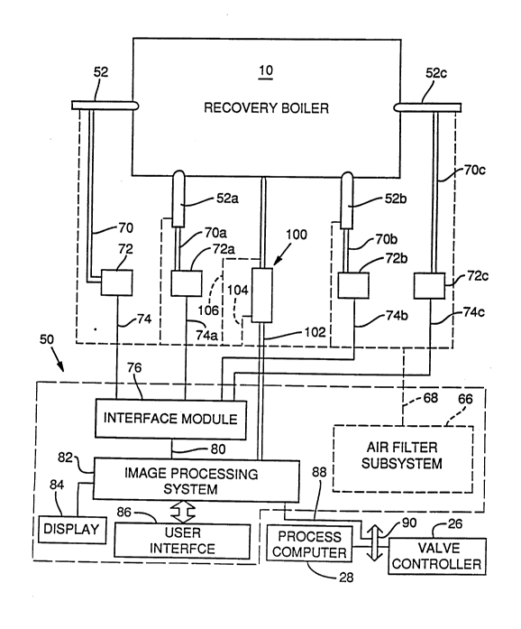
FIG. 2 is a schematic illustration of a carryover
particle detection apparatus in accordance with the
present invention having plural detectors positioned to
detect carryover particles at various locations in a
recovery boiler, the illustration also showing one form of
a subsystem for controlling the operation of the boiler in
response to the detected carryover particle information.
~ - 11 - 20~2797
FIG. 3 is an electrical schematic diagram of one
form of circuit usable in conjunction with the detectors -
of FIGS. 1 and 2.
FIG. 4A, 4B and 4C illustrate representative
signals at selected points in the circuit of FIG. 3.
DETAILED DESCRIPTION OF PREFERRED EMBODIMENTS
With reference to FIG. 1, one form of an
apparatus for detecting carryover particles in the
interior of a furnace 10 is indicated generally at 50.
This apparatus includes at least one carryover particle
_ detector 52, and preferably plural such detectors. Each
detector has an end 54 positioned, such as being inserted
into an existing port of the furnace, for monitoring a
portion of the interior of the furnace. These detectors
typically include a single point detector, such as a photo
diode or other optical detection device. On example of
such a detector is a UDT455 photo diode from United
Detector Technology. The photo diode is positioned behind
a lens for focusing the diode on a region of the furnace
of interest. A single point detector, if used, has a
number of advantages. For example, such a detector is
symmetric in viewing a region of a furnace of interest so
that its operation is independent of rotational
variations, about the axis of the detector, and is
therefore insensitive to such variations as the device is
installed. Also, these detectors are equally sensitive to
ca~ ver particles traveling in planes perpendicular to
the axis of the detector regardless of the direction of
travel of carryover particles in such planes. In a
3~ conventional manner, the detectors typically include an
air purging system for directing purging air across the
surface of the lens to sweep debris present in the dusty
environment of the furnace away from the lens. Also, the
detectors are typically recessed within the ports about
one to two inches from the edge of the port so that they
- 12 - 20~79~
do not project into the furnace where they may be impacted
by carryover particles.
In FIG. 1, the detector 52 is shown positioned
across from a "bull nose" section 46 of the furnace.
However, the detectors may be positioned at any suitable
location in an upper region of the furnace. In addition,
the detectors may all be located in a single plane at
distributed locations about the periphery of the walls of
the furnace. Alternatively, or in combination, the
detectors may be positioned to monitor portions of the
_ interior of the furnace at different elevations, as
indicated by the detector 52' in dashed lines in FIG. l.
In accordance with the present invention, the
detectors may be focused substantially at infinity. Due
to the opaqueness of the gases typically found within the
furnace 10, under these focusing conditions each detector
typically focuses on a volume having a length ranging from
0 to about 3 feet away from the side wall of the furnace
to which the detector is attached. In such a case, the
detectors do not distinguish between particles of a
relatively small size which are close to the detector and
particles which are of a relatively large size and which
are further away from the detector. Alternatively, the
detectors may be focused on a focal plane located closer
to the side wall of the furnace than with the focus at an
infinity -focus setting. In this alternative case, depth
of field carryover particle discrimination is possible.
That is, under these conditions, carryover particles
within a certain focal region or distance of the focal
plane of a detector, for example within about plus or
minus twenty percent of the distance from the wall of the
furnace to the focal plane, are in focus and are thus
detectable by the detector. In contrast, carryover
particles which are closer to the detector than this
distance and those that which are farther away tend to be
out of focus. Therefore, these signals may be ignored as
-
- 13 -
206279~
background noise in the detector output signal. Although
the approach of the Herngren patent utilizes an array of
detectors focused on a focal plane, in Hernqren, et al.,
as understood by the present inventors, the focal plane is
only about 2 to 3 inches away from the adjacent wall of
the furnace. The inventors believe that improved
detection results from a shift in the focal plane of the
detectors to a distance which is at least about one foot
from the adjacent side walls of the furnace because this
tends to increase the volume of the furnace being sampled
- to provide a more representative carryover particle count.
A signal processing system 56 is coupled to the
detectors, as indicated by lines 58 and 58' in FIG. l, for
receiving the detector output signals and for producing a
count signal corresponding to the count of carryover
particles detected by the detectors. The detectors
produce output signals which are markedly different upon
the passage of a carryover particle within the region of
the furnace being viewed by a detector. These detector
ou~u~ signals thus contain information on the occurrence
of carryover particles. Information from the carryover
count may then be displayed or utilized in the control of
parameters affecting the performance of the furnace. In
particular, signals from the signal processing system 56
may be delivered by a line 60 to the process computer 28
for use in controlling the furnace.
For example, increases in particle count rates
have been observed to occur in response to large rapid
changes in boiler operating conditions. Also, there may
be a correlation between the loading level or volume of
the bed 30 and the ~uantity of carryover particles which
is produced. Thus, upon the detection of an excessive
carryover particle count, the process computer 28 may act
by way of an interface (not shown) and a valve or damper
controller 26 to control air dampers 22, 24 and fuel
valves 42, 44 in an attempt to reduce the number of
- 14 - 20627~7
generated carryover particles. As one specific example,
the air flow dampers 22 and 24 may be opened to increase
the air flow and combustion rate to reduce the size of the
bed 30. As another specific example, assume that the
computer 28 has recently caused a change-in the settings
of a damper in a manner which produced an unacceptable
increase in the carryover particle count rate. In
response to the signal on line 60, the process computer 28
may return this damper to its previous condition to
10 r;ni~; ze the generation of carryover particles.
With reference to FIG. 2, one embodiment of the
apparatus of the present invention is shown in greater
detail. In this case, four detectors 52, 52a, 52b and 52c
are positioned at the same elevation of the furnace at
spaced apart peripheral locations along three of the sides
of the furnace. More or fewer detectors may be used as
desired and the detectors may also be located at varying
elevations, such as shown in FIG. 1 for detector 52'. In
one specific preferred approach, the detectors are in a
plane at the "bull nose" level of the boiler at the sides
of the boiler other than the "bull nose" side. In
general, the detectors are positioned high enough in the
furnace to detect burning particles that are likely to
still be burning when they reach the upper heat surfaces
and tubes of the boiler.
A conventional air filter subsystem 66 filters
air and delivers this air through purging lines 68 to the
detectors for use in purging or sweeping the lens of each
of the detectors. Such an air filter subsystem is also
used in the previously described TIPS ~ product available
from Weyerhaeuser Company.
The output signal from detector 52, and more
specifically in the illustratèd embodiment from the
detector diode, is preprocessed by circuitry at the
detector 52, fed by a line 70 to additional preprocessing
circuitry 72, and then by a line 74 to a commercially
-
- 15 - 2~62797
available computer interface module 76 as shown.
Similarly, the outputs from detectors 52a, 52b and 52c are
fed by way of respective lines 70a, 70b and 70c to
associated preprocessing circuits 72a, 72b and 72c and
then by respective lines 74a, 74b and 74c to the interface
module. Suitable preprocessing circuits are described in
greater detail in connection with FIGS. 3 and 4.
The interface module 76 converts the received
signals to a suitable digital form for delivery over lines
80 to an image processing subsystem 82. One suitable
_ interface module is an TIPS ~ 2000 interface module
available from Weyerhaeuser Company. One suitable image
processing subsystem is also the TIPS ~ system from
Weyerhaeuser Company. The imaging processing subsystem 82
includes a display, illustrated separately at 84 in FIG. 2
and a user interface, such as a keyboard, for use in
entering information into the image processing subsystem.
The image processing subsystem 82 performs a
number of operations on the count data received from the
interface module. For example, the image processing
system typically sums or otherwise combines the results of
the detector counts, which may again be expressed as count
rates, from all of the detectors utilized in the system.
Then, by way of display 84, the overall average carryover
particle counts and trends in overall counts may be
displayed. In addition, either alone or in combination
with the display of the overall count information, the
count from each of the detector locations, in this case
the four locations shown in FIG. 2, may also be
individually displayed.
With this information, an operator of the boiler
10 may observe an increase in the overall count from all
of the detectors. In addition, by then monitoring the
individual display of the counts associated with each of
the four individual detectors, the operator may determine
whether the carryover particle count is increasing
, _
- 16 - 20~797
generally throughout the furnace or only at selected
locations in the furnace. An indication that the
carryover count increase is the result of a localized
disturbance is implied from a disparate increase in the
count from one of the detectors (e.g. 52a) in comparison
to the count at the other detectors (e.g. 52, 52b and
52c).
In response to the count information, the boiler
operator may enter a command, by way of interface 86, to
the image processing subsystem 82 which is passed through
another interface module, not shown, and by a line 88 to a
data bus 90 and then to the process computer 28. This
command results in an adjustment of the performance of the
furnace, such as by controlling valve controller 26 to
adjust the dampers or valves as previously explained. In
addition, the system may operate automatically with count
signals being directly sent to the process computer which
then determines an appropriate command in response to an
increase or decrease in the carryover particle count.
The system of the present invention also
facilitates the cross correlation of carryover particle
counts to furnace operation parameters. For example, the
TIPS ~ system is capable of, among other tas~s, monitoring
the temperature of the bed 30. By correlating temperature
changes, or other information on furnace performance, with
CaL r ~over particle counts, an optimum set of parameters
for a particular furnace may be established which
minimizes the production of carryover particles. The
optimum set of parameters is typically a set of control
settings (e.g. fuel flow rate, air flow rate, fuel
viscosity, etc.) affecting furnace performance.
In accordance with the present invention, the
apparatus may also include an imaging sensor lO0 focused
on an interior region of the furnace for producing an
3~ image signal. This image signal is fed by a line 102 to
the image processing subsystem 82 and may also be
- 17 - 2~ 6279~
displayed on display 84. In a conventional manner, the
imaging sensor is also typically provided with a source of ~
cooling and purging air, by way of conduits 104, 106, from
the air filter subsystem 66. Although any suitable image
sensor may be used, typical sensors include a charge
coupled device (CCD) detector or a video camera system
such as described in U.S. Patent No. 4,539,588 to
Ariessohn, et al. may also be used. The unprocessed image
signal on line 102 from the image sensor is digitized by
the image processing subsystem 82 and displayed. From
- this display, the boiler operator may observe the
oc~ ence of carryover particles and compare the observed
information to the determined count. This enables the
boiler operator, for example, to obtain a visual
configuration of the occurrence of at least a portion of
the carryover particles being counted by the carryover
particle detection system.
With reference to FIGS. 3 and 4A - 4C, suitable
electronics for use in the apparatus of FIG. 2 will be
described. More specifically, light from the field of
view of the detector 52, as indicated by arrow 110 in FIG.
3, passes through a small lens and through an optical
filter (not shown) and falls upon a ultraviolet-enhanced
photo-detector 112. This detector 112 is connected in a
photoconductive mode with an integral amplifier 113. The
photo diode 112 produces a 0 volt output plus/minus 0.001
volts when the photo diode is not receiving any light.
The detector output on line 116 is fed to an optional gain
control amplifier 118 with a gain adjustment potentiometer
30 120.
The average analog value of the signals in this
specific circuit should not exceed plus/minus 7 volts
relative to ground potential (O volts). Peak voltages
also should typically not exceed about 10 volts in this
specific circuit. Optimum performance is typically
achieved when the average analog values are about 2 to 3
-
- 18 - 2062 7 9 7
volts above ground potential. The object of these
settings is to avoid the saturation of the optical ~
detector. The value of the analog output from the
amplifier 113 is adjusted by replacing the optical filter
with a higher or lower value to achieve these operating
conditions.
The signal from amplifier 118 is fed on a line
122 to a high pass filter 124. An exemplary signal on
line 122 is shown at FIG. 4A and includes gradually
- 10 varying background or noise signals, resulting from
- varying background light in the furnace, along with peaks
indicative of the occurrence of carryover particles. The
filter 124 minimizes the affect of these slowly varying
background changes as indicated by the filtered signal
shown in FIG. 4B. The filter typically comprises a 24db
per octave high pass filter, with a 3 db cut-off frequency
of 3 Hz. This filter removes most of the background
radiation from the detected signal.
The filter ouL~uL is fed by a line 126 to a first
input of a comparator 128. A reference voltage circuit
130 is coupled to the comparator 128 for providing a
reference or threshold voltage signal for the comparator.
As shown in FIG. 4B, the threshold level is adjusted to
eliminate or minimize the effect of background noise on
the detected carryover pulses. A typical threshold for
this circuit is approximately 0.5 to 1.0 volts above the
peak noise levels. The comparator illustrated in FIG. 3
o~L~uLs a logic "0" when the threshold, set by the
threshold or level adjust potentiometer 130, is exceeded.
When the signal drops below the threshold, the output of
the comparator returns to logic "1." An exemplary
inverted output from the comparator 128 is shown in FIG.
4C. The components described with reference to FIG. 3 to
this point are typically packaged as a printed circuit
board and included within the detector 52.
-- - 19 206279~
The comparator output appears on line 70 and is
typically coupled to a circuit 72 on a circuit board which ~
is spaced from the detectors. The components on circuit
72 are thus more isolated from the adverse heat and other
environmental conditions associated with the furnace. The
signal on line 70 is fed to a count detection input of a
microprocessor 134. The pulses received on the input pin
to the microprocessor are counted. Although a single
microprocessor with plural inputs may be used for
receiving the signals from all of the detectors, more
- typically a separate microprocessor is associated with
each detector.
An interval switch, indicated at 136 in FIG. 3,
may be used to establish a time interval over which
carryover particles are counted. When the interval
selected by this interval switch has ended, the carryover
particle counter value and the interval setting may be
read by a mi~Lo~rocessor scaling routine to provide count
rate information on a per unit time basis. These time
intervals may be repeated to provide counts on a per
interval basis as well. Alternatively, the amount of time
required for a specific number of counts to occur may be
measured with the counts number and then being divided in
the mi~lo~L Gc~c-cor by this measured time to produce a
count rate. In general, when a count in the form of a
count rate is desired, a meçh~ni-cm is employed which
produces a result expressed in units of counts per time.
In the interval approach, the scaling routine divides the
count value by the interval setting and uses a full scale
setting (set by a scale switch 138) to create an 8-bit
number. If the result exceeds 8-bits, an overflow
indicator, such as an LED 140 on display board 142, is
activated and the 8-bit valuè (or other count rate
indicator) is set to 255, a full scale output. The 8-bit
value is transmitted over a line 150 to a
digital-to-analog converter 152. In addition, the
. .
~_ - 20 - ~062797
digital-to-analog converter output is fed over a line 154
to a driver lS6, such as a lB21 optical isolating driver
from Analog Devices. The output of driver 156, on
line 74, is at a suitable level for delivery to the
interface module 76 (FIG. 2). For example, in a typical
pulp mill, signals at a 4 ma. level (corresponding to a
zero output) and a 20 ma. level (corresponding to a
full-scale output) are used. Another common mill scale
range is from zero to 10 volts. For such mills, the
output of driver 156 is adjusted for this latter scale.
- A full-scale output occurs typically when the
average number of detected carryover particles per second
equals or exceeds the setting of the scale switch 138.
For example, for a scale switch position of zero, the
maximum average of detected carryover particles per second
may be one; for a scale switch position of one, a maximum
average of detected carryover particles per second may be
two; for a scale switch position of two, the maximum
average is five; for a scale switch position of three, the
maximum average is ten; for a scale switch position of
four, the maximum average is 20; for a scale switch
position of five, the maximum average is 50; and for a
scale switch position of six, the maximum average is 100.
Also, typical time intervals established by interval
switch 136 are respectively 1 second, 2 seconds,
5 secon~c, 15 seconds, 30 seconds, 1 minute, 2 minutes,
5 minutes, and 15 minutes.
The interval switch 136 is typically eliminated
by simply measuring the amount of time required to achieve
a carryover particle count of a particular magnitude and
dividing the count by the measured time. Also, the scale
switch 138 is also typically eliminated by providing the
microprocessor with a mechanism for compressing the scale.
For example, by expressing the count rate on a logrithmic
scale in the microprocessor, the count rate may be
:, '
- 21 - 20 62 79 ~
accommodated without the occurrence of an overload
condition.
The display panel 142 may also include indicators
160, 162 for other purposes. For example, indicator 160
may comprise an LED or other visual or auditory indicator
which is activated, for example, for l/30th of a second,
to indicate that a carryover particle has been detected.
In addition, the indicator 162, such as an LED, may be
used to indicate the end of each interval if a times
interval approach is being used. Also, a reset-switch 164
may be provided to reset the microprocessor to a zero
count.
The information on carryover particle counts may
be displayed for observation by an operator of the boiler
to verify boiler performance. In addition, this
information may also optionally be used in the control of
parameters, such as fuel and air flow, affecting boiler
performance.
Having illustrated and described the principles
of our invention with respect to several preferred
embo~;r^nts, it should be apparent to those of ordinary
skill in the art that our invention may be modified in
arrangement and detail without departing from such
principles. For example, the electronic circuitry used to
~5 obtain a count of carryover particles may be substantially
modified while still performing this function. We claim
as our invention all such modifications which fall within
the scope of the following claims.