Some of the information on this Web page has been provided by external sources. The Government of Canada is not responsible for the accuracy, reliability or currency of the information supplied by external sources. Users wishing to rely upon this information should consult directly with the source of the information. Content provided by external sources is not subject to official languages, privacy and accessibility requirements.
Any discrepancies in the text and image of the Claims and Abstract are due to differing posting times. Text of the Claims and Abstract are posted:
| (12) Patent: | (11) CA 2062907 |
|---|---|
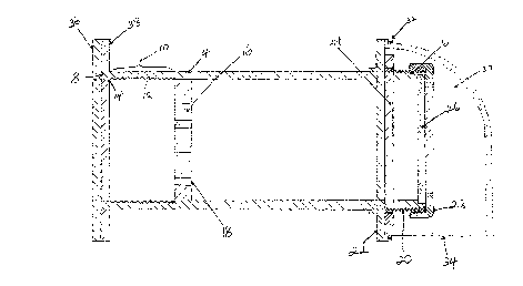
| (54) English Title: | WALL VENT |
| (54) French Title: | EVENT D'AERATION MURAL |
| Status: | Term Expired - Post Grant Beyond Limit |
| (51) International Patent Classification (IPC): |
|
|---|---|
| (72) Inventors : |
|
| (73) Owners : |
|
| (71) Applicants : | |
| (74) Agent: | DARYL W. SCHNURRSCHNURR, DARYL W. |
| (74) Associate agent: | |
| (45) Issued: | 1998-10-27 |
| (22) Filed Date: | 1992-03-12 |
| (41) Open to Public Inspection: | 1993-09-13 |
| Examination requested: | 1993-04-06 |
| Availability of licence: | N/A |
| Dedicated to the Public: | N/A |
| (25) Language of filing: | English |
| Patent Cooperation Treaty (PCT): | No |
|---|
| (30) Application Priority Data: | None |
|---|
An air vent is installed in an outside wall
and contains a screw thread on an inner surface of an
inner end. An abutment is located inside the vent. A
cap is shaped to screw into the vent and rests against
the abutment when it is in a closed position. The cap
and the abutment contain openings that permit air to
flow through the vent when the cap is open and prevent
air from flowing through the vent when the cap is
closed. The cap can be partially open so that some
air flows through the vent. The vent can be easily
installed and maintained. It can be left open when
the building is unoccupied, without any sacrifice in
security.
Cette invention concerne un dispositif d'aération monté dans un mur extérieur et comportant un filetage intérieur du côté intérieur. Un épaulement est prévu dans le dispositif d'aération. Un capuchon à visser dans le dispositif prend appui contre l'épaulement lorsqu'il est en position fermée. Le capuchon et l'épaulement comportent des ouvertures permettant la circulation d'air à travers le dispositif lorsque le capuchon est ouvert, aucune circulation d'air n'étant possible lorsque le capuchon est fermé. Celui-ci peut être partiellement ouvert pour permettre une certaine circulation d'air. L'objet de l'invention est facile à installer et à entretenir. Il peut être laissé ouvert lorsque le bâtiment est inoccupé, sans compromettre la sécurité de celui-ci.
Note: Claims are shown in the official language in which they were submitted.
Note: Descriptions are shown in the official language in which they were submitted.
2024-08-01:As part of the Next Generation Patents (NGP) transition, the Canadian Patents Database (CPD) now contains a more detailed Event History, which replicates the Event Log of our new back-office solution.
Please note that "Inactive:" events refers to events no longer in use in our new back-office solution.
For a clearer understanding of the status of the application/patent presented on this page, the site Disclaimer , as well as the definitions for Patent , Event History , Maintenance Fee and Payment History should be consulted.
| Description | Date |
|---|---|
| Inactive: Expired (new Act pat) | 2012-03-12 |
| Inactive: Office letter | 2010-06-08 |
| Inactive: Reversal of will be deemed expired status | 2010-06-08 |
| Inactive: Payment - Insufficient fee | 2010-03-23 |
| Inactive: Office letter | 2010-03-23 |
| Letter Sent | 2010-03-12 |
| Inactive: Adhoc Request Documented | 2009-05-22 |
| Inactive: Late MF processed | 2009-04-30 |
| Letter Sent | 2009-03-12 |
| Grant by Issuance | 1998-10-27 |
| Pre-grant | 1998-06-09 |
| Inactive: Final fee received | 1998-06-09 |
| Letter Sent | 1998-01-22 |
| Notice of Allowance is Issued | 1998-01-22 |
| Notice of Allowance is Issued | 1998-01-22 |
| Inactive: Application prosecuted on TS as of Log entry date | 1998-01-07 |
| Inactive: Status info is complete as of Log entry date | 1998-01-07 |
| Inactive: IPC removed | 1998-01-05 |
| Inactive: First IPC assigned | 1998-01-05 |
| Inactive: IPC assigned | 1998-01-05 |
| Inactive: Approved for allowance (AFA) | 1997-12-08 |
| Application Published (Open to Public Inspection) | 1993-09-13 |
| All Requirements for Examination Determined Compliant | 1993-04-06 |
| Request for Examination Requirements Determined Compliant | 1993-04-06 |
| Small Entity Declaration Determined Compliant | 1992-03-12 |
There is no abandonment history.
The last payment was received on 1998-02-09
Note : If the full payment has not been received on or before the date indicated, a further fee may be required which may be one of the following
Patent fees are adjusted on the 1st of January every year. The amounts above are the current amounts if received by December 31 of the current year.
Please refer to the CIPO
Patent Fees
web page to see all current fee amounts.
| Fee Type | Anniversary Year | Due Date | Paid Date |
|---|---|---|---|
| MF (application, 6th anniv.) - small | 06 | 1998-03-12 | 1998-02-09 |
| Final fee - small | 1998-06-09 | ||
| MF (patent, 7th anniv.) - small | 1999-03-12 | 1999-02-15 | |
| MF (patent, 8th anniv.) - small | 2000-03-13 | 2000-02-18 | |
| MF (patent, 9th anniv.) - small | 2001-03-12 | 2001-01-12 | |
| MF (patent, 10th anniv.) - small | 2002-03-12 | 2002-02-19 | |
| MF (patent, 11th anniv.) - small | 2003-03-12 | 2003-02-18 | |
| MF (patent, 12th anniv.) - small | 2004-03-12 | 2004-03-12 | |
| MF (patent, 13th anniv.) - small | 2005-03-14 | 2005-03-07 | |
| MF (patent, 14th anniv.) - small | 2006-03-13 | 2006-03-09 | |
| MF (patent, 15th anniv.) - small | 2007-03-12 | 2007-03-08 | |
| MF (patent, 16th anniv.) - small | 2008-03-12 | 2008-02-27 | |
| Reversal of deemed expiry | 2009-03-12 | 2009-04-30 | |
| MF (patent, 17th anniv.) - small | 2009-03-12 | 2009-04-30 | |
| MF (patent, 18th anniv.) - small | 2010-03-12 | 2010-02-25 | |
| MF (patent, 19th anniv.) - small | 2011-03-14 | 2011-03-01 |
Note: Records showing the ownership history in alphabetical order.
| Current Owners on Record |
|---|
| MALBEE B. SIRJOO |
| Past Owners on Record |
|---|
| None |

