Note: Descriptions are shown in the official language in which they were submitted.
WO 91/01036 PCIIEP90/01137
2 ~ 7 7
ENERGY SOURCE SYSTEM
This invention is related to an energy source system and eo a
method for producing energy.
In particular the present invention provides a method for
recovering energy from metal hytride type lattice systems. The
strange behaviour of hydrogen in metals, in particular in palladium
has been studied for well over 100 years. Also the presence and
proper~ies of deuterium in palladium have been investigated~ It is
known that a large amount of hydrogen and/or deuterium, being in
the ion-form, can be incorporated in metals such as palladium, thus
forming a metal hydride type lattice system~
Although such systems are very interesting from a scientific
point of view they have not attracted practical interest since the
systems seem to absorb rather than to release energy. It would be
very interesting to design and operate a system based on hydrogen
isotopes and metals which would be capable of delivering energy.
It is therefore an object of this invention to provide an
energy delivery process driven by a system filled with particles of
at least one hydrogen isotope.
It is another ob;ect of this invention to provide an energy
delivery system equipped with controllable starting means, shut
down means, and restarting means.
It is yet another object of the present invention to provide
an operable energy source system having operating conditions which
can be modified easily.
It is a further ob;ect to provide an energy source system
which is suitably coupled to a working system.
Furthermore it is an object of the present invention to design
and develop an energy source system which can be integrated in
existing power cycles.
''-
'~ ,.
- ' ' '
,
W O 9~/01036 PCT/EP90/01137
2 0 6 2 ~ 7.~ - 2 -
The invention therefore provides a method for producing
energy, comprising,
- filling a body with at least one hydrogen isotope, at least a
part of the body comprising at least one ~etal capable of
S forming a metal hydride type lattice system,
- arranging the body filled as at least a part of the one
conductor element of a capacitor means within an electrical
circuit, the other conductor element of said capacitor means
being connected wieh an externally controllable voltage supply
means,
- operating said voltage supply means, and
- recovering energy produced within said body by operating said
volta~e supply means.
In an advantageous embodiment of the invention filling the
body is carried out by arranging the body as an electrode means in
an operating electrical circuit and exposing the body to said
isotopes.
In another advantageous embodiment of the present invention
filling the body is carried out by arranging the body in a pressure
vessel containing under pressure a gas comprising at least one kind
of hydrogen isotopes and exposing the body to said gas.
In a further embodiment in accordance with the present
invention filling the body is carried out by arranging the body as
an electrode means in an electrochemical system and exposing the
body to ions from said electrochemical system.
In accordance with the method of the present invention said
body is advantageously exposed to a flow of said isotopes being
generated by an electrical discharge, and the energy produced is
recovered from a heat exchange means.
Furthermore the invention provides an energy source system,
comprising:
- a body, at least a part of the body comprising at least one
metal capable of forming a metal hydride type lattice system
and being at l~ct a part of one conductor element of a
capacitor means of which the other conductor element is
' .
, - .,, ,: , . ~ . :
::
WO 91/01036 PCl-/EP90/01137
20629~
connected to an externally controllable voltage supply means,
sai~ capacitor means and said voltage supply means for~ing an
electrical circuit,
- a supply means for supplying at least one hydrogen isotope to
S be introduced into said body, and
- a recovering means for recovering energy produced within said
body.
Advantageously said system enables a reliable and controllable
coupling to a working machine allowing complete integration with a
power cycle.
In an advantageous embodiment of the system in accordance with
the present invention the body is an electrode means in an
electrical discharge circuit, the circuit further comprising said
supply means wherein the electrode means is the one conductor
element of a capacitor means. Furthermore said system comprises a
shielding means to be interposed between said body and said supply
means capable of regulating the entering of isotopes into said
body.
In another advantageous embodiment of the system of the
present invention the body is arranged in a pressure vessel, the
supply means comprising a pressurizing device for pressurizing a
gas comprising said isotopes~
In yet another embodiment of the system in accordance with the
present invention the body is an electrode means arranged in an
electrochemical system acting as the supply means for supplying
ions of said isotopes.
Further datails of thè invention will be described now by way
of example with reference to the accompanying drawings.
Fig. lA and Fig. lB are drawings demonstrating schematically
the principles underlying the present invention.
Fig. 2 shows an advantageous embodiment of the energy source
system in accordance with the present invention.
Before disclosing specific features and further details of the
prssent invention a short outline of some electrostatical
principles is given, thereby referring to figs. lA and lB.
W O 91tO1036 PCT/EP90/01137
2 0 6 2 9 7 ~ -
In fig. lA a metal/dielectric interface, for example in a
capacitor means, is shown schematically. The graph as shown can be
considered as a cross section. On the horizontal axis a distance
parameter r is used with r - O at said interface (the vertical line
at r - O schematically representing the interface).
In fig. lB the same interface is indicated in a graph showing
schematically the distance r on the horizontal axis as specified
above and the electrical field strength E on the vertical axis.
In detail in fig. lA the hatched part of the graph to the
right of r - O, referenced by l, represents the metal functioning
as a conductor element in a capacitor means, wheraas to the left of
r - O, referenced by 2, the dielectric is shown.
In fig. lB the E vs. r diagram represents the situation of an
electrically charged capacitor. As known from basic physics the
lS electrical field within a metal is zero and has a constant value in
a dielectric, for example in a plate capacitor. In order to
normalize voltage references like earthening references and charge
differences the electrical field values E are presented as modular
values IEI. The constant electrical field value referred to herein-
above is indicated as Eo. ~ -
As set forth above the body caD be filled in an electrical
way, in a mechanical way, or in an electrochemical way.
Respectively, in the electrical way of filling said body
plasma-like conditions are created around the body, for example by
arc, spark, or corona discharging of a gas containing at least one
kind of hydrogen isotopes, and thus molecules, radicals and/or ions
resulting from said conditions being allowed to enter into the
body. It is also possible to create an electrical field in such a
way that said body is exposed to a beam of ions of said isotopes.
When being filled in the mechanicai way the body is arranged
within a pressure vessel, comprising a gas of said isotopes, the
gas being pressurized at a suitable temperature and thus isotopes
being introduced into said body.
In the electrochemical way the body is ~n electrode means
arranged in an electrolyte, the body being filled directly with
ions of said isotopes originating from an electrolytic process.
. ' . ' : , , . .. . ~ . . : . ' -
W O 91/01036 PCT/EP90/01137
2~2~77
s
Of great importance for the principle underlying the present
invention is the occurrence of an electrical surface charge within
the metal at the metal/dielectric interface~ For example in a
capacitor-type set up such a surface chsrge will result in an
effective charge separation in accordance with the so-called
phenomenon of electrical influence (or elec~rostatic induction).
Consequently it is possible to charge positively or negatively a
conductor element being influenced in the above way. Furthermore,
electrically influencing of an already charged body allows
repositioning of charges introduced before~
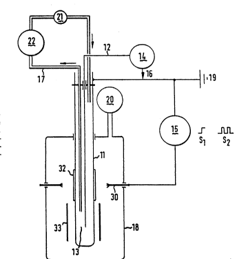
Now referring eo fig. 2, an advantageous embodiment of the
energy source system in accordance with the present invention is
shown wherein the body is advantageously filled with at least one
kind of hydrogen isotopes in the above-mentioned electrical way.
The above-mentioned method for producing energy and the related
ensrgy source system will be disclosed in more detail.
In fig. 2 the system as disclosed comprises an elec~rical
circuit wherein a body 11 is arranged as an electrode means. In
said circuit a supply means 15, being a high voltage supply means,
is connected, at one side with both earth 19 and said body 11, and
at the other side with an electrical discharge device 30
In a further embodiment of tbe present invention said
electrode means is the one conductor element of a capacitor means,
the other conductor element 12 being juxtaposed, with a dielectric
element 13 therebetween.
Said other conductor element 12 can be comprised also in the
above electrical circuit or can be implemented in a separate
circuit.
In fig. 2 a controllable voltage supply 14 coupled to the
other conductor element 12 is shown, either to be operated
separately from the circuit 11, 15, 30, or to be connected
therewith by means of a connector 16. Further detailed embodiments
of the circuitry will be discussed below.
In the process a~r.ording to present invention the body 11 has
to be filled with molecules, radicals and/or ions of said hydrogen
, . , . ' ~ ` ' ' ~; ;. .
- ~
.:
W O 91/01036 PCT/EP90/Olt37
2 û ~ ~ ~ 7 ~
- 6 -
iso~opes. Therefore the above high voltage supply means 15 is
connected with the above-~entioned electrical discharge device 30
for suFplying said isotopes which is arranged in a chamber 18. Said
chamber including said body 11 forms the heart of ehe energy source
system, as such eo be considered a reactor.
Said chamber 18 is connected with a gas supply device 20 for
supplying a gas of ae least one hydrogen isotope. For e~ample
deueerium as well as mi~tures of hydrogen (H2) and deuteri~m (D2)
can be supplied~ Furthermore said gas supply device comprises a
pressure control means in order to create suitable pressure
conditions within said chamber. When supplied a number of molecules
will be excited energetically to their radical- or ion-form by
means of the discharge device 30. As will~be clear to those skilled
in the art, different types of electrical discharge devices like an
arc, spark or corona discharge device could be employed. So the
body 11 is e~posed to said isotopes.
A further importane feature is the way of operating the high
voltage supply means 15 which controls the electrical discharge
device 30. Generally the high voltage supply means is giving a
DC-voltage having a continuous or pulsed form as shown in fig. 2 by
the signal forms 51 and s2 respectively.
Furthermore, electrically influencing body 11 is achieved in
the capacitor arrangement by controlling the voltage supply 14. As
can be seen in fig. 2 said voltage supply 14 is connectable with
the circuit 11, 15, 30 by mesns of the connector 16, i.e. at any
position within the circuit.
From the foregoing it will be clear to those skilled in the
art that driving said capacitor can be realised in any suitable
way. -
For example, the combination of voltage supply 14 and .
connector 16 can be e~ployed as a neutralization means for
neutralizing the electrical charges entered into and consequently ~ :
having positions in the lattice system of said body 11.
Next, entering of the charges will be slowed down after a
3S certain amount of ions, however, because of increacing electrical
. .
- . . ., . ........... . ,~ : ,....... : -
' ' '
:.
WO 91tO1036 PCT/EP90/01137
2~52977
- 7 -
repulsive forces from charges already present within said
conductor. Furthermore a dielectric breakdown in the dielectric 13
has to be avoided because of possible overcharging said conductor
elements. Therefore said ions are to be neutralized repetitively by
means of the above said neutralization means 14, 16.
In another embodiment of the circuit a voltage can be applied
to the other conductor element 12, thereby externally affecting the
electrical charge distribution present within the body 11. In
particular this will be advantageous when the controllable voltage
supply 14 is operated pulsewise and intermittently with respect to
the pulses of the high voltage supply means 15; the amoune of
energy produced will increase significantly.
Furthermore in an advantageous embodiment the voltage supply
14 and connector 16 can be combined and can merely be operated in
lS the form of a switch connected between the other conductor 12 and
earth 19 thus functioning as a charge supply device, the switch
being also capable to be operated pulsewise; for example when the
switeh operates as a spark supply means, the supply means lS can be
diseonneeted from the body 11 (for reason of clarity not shown in
fig. 2).
In the above-mentioned embodiments the body 11 is filled with
hydrogen isotopes, in particular D, in the eleetrieal way. However,
in the event that said body is filled in the electrochemical or
mechanical way only the electrieal cireuit made up by the body 11
(being operated as a capacitor means) and the electrical circuit
means 12,14 and 16 have to be eonsidered.
For those skilled in the art it will be elear that in such
event the eontrollable voltage supply 14 is implemented
advantageously in sueh a way that eleetrieally influencing of the
filled body is applied optimally in order to affect the position of
the hydrogen isotopes entered, thereby reeovering energy
effieiently.
For example the eontrollable voltage supply 14 comprises an `
ignition deviee tuned to the eapaeitor means 11, 12 having a well
determined capacitanee. In partieular said ignition device
~ ~ ;
.
.. :: : ::::. :
; : : .,
,- . ' ::`,: :''-. ` .. .~ . :
: ., , ' : , ~- ;
:: : ~. :::: : .
.. . . ~
. .. : . : ,.; :
W O 91/01036 2 ~ ~ 2 9 7 7 PCTtEP90/01137
- 8 -
generates high voltage pulses over the conducror elements causing
~ransient electromagnetic fields in the conduc~or elements of said
capacitor.
As stated above, recovering of energy from at least one
electrode means filled with said isotopes is aimed at. Therefore at
least a part of said body ll has to be a metal or alloy forming a
hydride type lattice system; said metal or metals having vacancies
in their d and/or higher atomic energy levels and said isotopes
being in the ion-form after having been introduced into the la~tice
system. In particular palladium tPd), titanium (Ti), nickel (Ni)
and lanthanum (La~ are appropriate elements for forming such a
lattice system. Suitably said part is a layer 32 of at least one
such element arranged upon the body ll. For example the layer is
soldered upon said body. Alternatively said layer is deposited upon
said body, for instance by using the technique of chemical vapour
deposition tCVD).
The energy produced within said body, emanates from physical
and/or chemical processes. Recent physical explanation converges on
nuclear fusion, also referred to as cold nuclear fusion or even
piezonuclear fusion.
As dielectric element 13 a heat exchange means is chosen
capable for recovering energy produced within said body. Both a
solid arranged as an energy transfer means and a fluidum or fluidum
flow respectively as an energy-transfer or an energy transport
means can be used. Furthermore channels passing through said solid
and conducting a fluidum or fluidum flow like above can be employed
also.
Advantageously the dielectric element includes or is part of a
power cycle means, reference number 17 representing a circuit means
allowing energy recovery. As shown in fig. 2 by way of example said
circuit means is a fluidum conduit means, the fluidum flow
direction is indicated by arrows.
In a further embodiment of the above set-up the fluidum is
pressurized in a pumpin~ or pressurizing device 21 to enhance the
- : ' . ~ .
:,' ' , ~
- . .
. . .
W O 91/01036 2 ~ 7 7 PCT/EP90/01137 .
efficiency of the ener~y recovery. Advantageously, pressures
between 100 kPa and lO000 kPa will be used.
As a fluidum hydrocarbons and/or derivatives thereof, and also
water, can be suitably applied. In particular hydrocarbons and/or
derivatives thereof, advantageously having large dielectric
constants and breakdown values are particularly preferred.
The energy recovery can be controllably achieved either
continuously or batchwise. Moreover, the electrical set up allows
energy recovery and filling the body which can be effected
simultaneously or intermittently as set forth above. So it appears
to be advantageous to arrange a shielding means 33 within chamber
18 which can be placed between the discharge device 30 and the body
ll provided with the layer 32. So filling said body with isotopes
can be regulated.
As can be seen in the set-up of fig. 2 (assuming a
cross-sectional view) a cylindrical body, being the electrode means
ll, c.q. the one conductor element of the capacitor as explained
above, surrounds the other electrode 12 arranged as an inner
electrode within the cylindrical body.
The electrical discharge device 30 comprises at least one
annulus means surrounding the body ll, provided with conductor
brushes as electrical discharge means at its inner edge and
connected with the high voltage supply means 15 at its outer edge
capable of creating sparks or a continuous arc there between.
The above-mentioned shielding means 33 is suitably a cylinder
which can be interposed between the annulus and the electrode
means.
Furthermore, the body ll, and in particular the layer 32, as
shown in fig. 2, faces conductor brushes of the electrical
discharge device 30.
The above energy recovering means can be coupled to a working
machine 22 resulting in an integrated power cycle. Thus, existing
cycles can be implemented economically with the source system in
~ecordance with the present invention.
. . - -: ' '., , ~ ~
.: :. , : ~:
-: , . . : - :
, : ' ' : ~ , ; . . . :
. . . : : :: .. - : .,, ,, .:
:: : : : : - .. , -
.: , ....
W O 91/01036 PC~/EP90/01137
,
7 7 lo -
Yet another aspect of the present invention will be elucidated
hereafter. As stated above for the different filling options, i.e.
the electrical, the mechanical and the electrochemical case, said
electrode means is filled with at least one hydrogen isotope. In
said options at least a part of the electrical charges of the
conductor elements have to be neutralized in order to continue said
entering and filling process in a reliable and controllable way.
Said neutralizing can be effected by means of the neutralization
means 14, 16 as e~plained above and shown in fi~ 2. Generally said
neutralization ~eans comprises a pulsating charge supply device
having a pulse~operatin~ ran~e from 10 Hz to 1 MHz.
The combination of the controllable voltage supply 14 and the
connector 16 can be operated simply in the form of a switch between
the other conductor 12 and earth 19, thus functioning as a charge
supply device having also a pulse operating range.
Additionally when applying the pulsemode, in particular when `
the ignition device is used as explained above, transient electric
fields will be created within the conductor elements of the
capacitor, especially within the layer 32. A suitable pulse of the
electrical charges of the conductor form has to be chosen in order
to maximize the transient field efficiency.
Furthermore the connection by means of the connector 16
between the controllable voltage supply 14 and said one conductor
element, especially the layer 32, has to be effected in such a way
that dependent on the form of the layer 32 the transient field
propagation is as large as possible. This can be suitably achieved
when connector 16 is a conductor wire wrapped around the body 11
having a cylinder form and provided with the layer 32.
Detailed experiments have been carried out to chart the ~`
conditions under which energy recovery is obtained. .
In the examples hereafter experimental results obtained are :`
discussed in detail. Said results are gathered in the table below.
EXAMPLE I
In the experiments pertaining to this example ;set I and set
II, see table below) a Pd-layer soldered upon an outer electrode of
, . . . .. . . . . ..
,'" `` ~ :
~:
WO 91/01036 2 ~ 6 2 ~ 7 7 PCT/EPgO/01137
steel having a cylindrical form and open at the upper side was
filled with deuterium to PdDX with x up to 0.10 (or a concentration
of 10%) by means oi a corona discharge device within chamber 18 as
shown in fig. 2.
The discharge causes voltages of 10-12 kV at frequencies in
the range from 100 to 3000 Hz. In set I only one annulus was used,
whereas in set II three annuli were used which are separately
connectable and enable a more precise control of the experiments.
In order to effect the capacitor set-up a metal tube was
positioned within said cylinder to function both as the other
conductor element 12 of said capacitor and as an energy transfer
conduit means~
By way of arranging a shielding mesns 33 in the form of a
metal cylinder between said electrode and said brushes blank
experiments were carried out. Then, no energy could be recovered at
all during discharging under otherwise identical conditions.
A further important feature lies in the dynamic charac~er of
the experiments: i.e. an energy-rec~very agent is circulated within
a power cycle by the pumping or pressurizing device 21 as shown
schematically in fig. 2. Said agent is introduced into the reactor
via the above said metal tube as energy transfer conduit means and
is carried back between the outer wall of said tube and the inner
wall of the outer electrode by the pumping device, all forming part
of the power cycle for recovering energy. In the present
experiments DIALA-F-oil (RTM) was used as energy-recovery agent. ~
The oil flow rate in the reactor was measured. ~ `
By measuring temperatures at a number of points, both nearby ` `
the capacitor and along said cycle, during well-defined time ~ -
intervals making up a total meaning time, power values P,
calculated for said intervals and defined for these particular sets
as peak power values, have been determined. Furthermore deviations
~P for said P values are determined by taking in account
temperature differences, mainly caused by temperature background
fluctuations, in particular those differences which were measured
nearby the capacitor. Temperatures between 20 and 40 C were
measured.
'' '' ~ ,
~' ' "' ' . .
.' 'I 1 ' ~' ~ ';; '' ' ~.''
W O 91/OtO36 7 7 PCT/EP90/01137
- 12 -
In the experi~ents reported as set I and II a DC voltage of
25-40 kV was coupled continuously between the two conductor
elements of the capacitor means.
EXAMPLE II
In this example, covering experiments reported in set III and
set IV as shown in the table, a second approach for operating the
energy source system is followed~
Firstly a steel body having a Pd-layer soldered thereupon was
filled outside the reactor with deuterium. Deuterium gas at a
pressure of 25 bar and at a temperature of 225 C was introduced
into the palladiun7 layer during a period of 48 hours. This leads to
a recovery-starting concentration x within the PdD~-system of 0.25.
Next the body filled was placed within the reactor and an
ignition device 14 as explained above was connected thereto.
High-voltage pulses having peak values of 2000 V and pulse
frequencies in the range between 2000 and 3500 Hz were fired
between the conductor elements of the capacitor means resulting in
recovering of energy as shown in the table below.
Like for the sets I and II of Example I, for set III also the
dynamic approach was applied. On the contrary the experiments
reported in set IV have been carried out under static conditions, -~
i.e. within a Joule meter containing a well known amount of oil and
for which a heat capacity of 391 J/-C and a heat transfer
coefficient of 79 J/h.C had been determined prior to the start of
the above experiments. As dielectric element and heat recovery
medium again DIALA-F-oil was used. For the different set
IV-experiments corresponding different oil contents were used.
Additionally to the above said peak power values also mean
power values, being power values calculated for the total measuring
time, have been determined.
Especially set III and IV demonstrate a reproducible energy
output. For the sets III and IV temperatures between 20 and 40 C
were measured.
As can be seen from the Table the meqn P-~a7u~s for set IV has ~-
appeared to stabilize around a recovery power of 0.23 U.
:
W O 91/01036 PCT/EP90/01137
2~2977
- 13 -
Furthermore in most experiments of set III and set IV one side
of the Lgnition device had been connected advantageously around
layer 32 on body ll by means of a conductor wire which was wrapped
around the cylinder as explained above. Only for the set IV
experiment having a mean P-value of 0~180 W a pointwise connection
of the conductor wire was used.
:' '
-: , : : . . . , ' . - .; , ~ . .: . .
''.~ ~ : ' ':
~ . .
WO 91/01036 PCI'/EP90/01137
2 ~ 6 ~ ~ ~ 7
~ I X ~
o , ~ .... , ..... ....... ,, ..
30 c
E
~~ u~ u~ ~n c~ J
_~ ~ E
c~ o~ ~ o~
O ~ _ ~ _~ ~ ~ 1 ~
C~ '
~,~
::)_ ~ ~ ~ C~ ~ o
~ ,E ~ ~ ~ ~ `J ~
.
~X d~
~_ O O O ~ I~ u~ ~
C~ X ~ 1 c~ c~ ~ N ~ ~ C~ C`~ ~ ~ ~ ~ N
r~ ~ ~ c
N C`J U~ I
E_ ~ _
~~ C~ C~ C~ O O O O O O .~ .
~1~ _1 o o o o o o o o o o o o o o o ~
~ o ~ . '
_I -- d` ~0 _ ~ ~ X ~ ~ ~ ~
C ~-~ ~ ~ `5 ~ C~ _ ~ _ ~ _ ~ C`J .,
3 . , . ~ . o o o o o o o o o O o o O
E
V ~ ~ ~ ~ o oo 1~ ~ CO ~ o o~
a~ 3 ~ _ ,~ ~ ~ ,~ o
~ J _ _ o o o o o o o , .....
. .
o
o cl a a a a a c~ c~ a a a a a a a a ~ a
~ ~ ~: '
_ E I ~ ~ . . + + + + + + + + + + + + +
o ~
3 ~ + + + + + . . . . . . . . . , . . , -
. ' , :'~
o~u~
~ C ~ ~ ~ ~ ~ ~ I
o~ X ~ ~ ~ ~ ~ ~ ~ ~ ~ I ~ ~ ~ ~ ~
cn a) e ~ ~ ~ ~ ~ ~ ~ ~
:
.. ~ . -
~ ". ' ':, ., ~' ''
.: .
W O 91/01036 PCTtEP90/Olt37
20~2977
- 15 -
Wieh respece to the energy balance of the operating step of
the method in accordance with the present invention, in particular
related to the power values determined for set III and set IV, the
following should be noted. For electrically influencing the metal
hydride system (by operating the ignition device) an amount of
input operating power of 0.050 W was needed. For the resulting
total power release, an amount of 0~28 W was determined
Furthermore all kinds of possible losses feasible within said
lattice system have been checked. Losses possibly caused by for
example laetice deformation, dielectric loss, chemical reactions,
and internal sparking have been taken in account. Weighing all
these factors an amount not exceeding 0.050 W could be determined.
Thus a recoverable power output of between four and five times the .
input operating power has been obtained.
In order to establish unambiguously the reproducibility and
recovery of the system a number of blank experiments was carried
out~ Both measuring on the PdD-system without triggering, and next
without inner tube, and triggering the body having an outer
conductor element only consisting of steel, did not reveal any
2Q detectable energy recovery beyond the 0.050 W loss value discussed
hereinabove.
It will be clear that an advanced control device controlling
automatically the interacting activities of the above system
elements, in particular with respect to their operating modes, can
improve further the energy output and efficiency of the above
method for producing energy from said energy source system.
~arious modifications of the present invention will be .:
apparent to those skilled in the art from the foregoing description
and accompanying drawings~ Such modifications are also within the
scope of the present invention. ~-
''` " ~ :- ' ': ' ':` "' ';`'