Note: Descriptions are shown in the official language in which they were submitted.
20630~
BACKGROUND OF THE INVENTION
This invention relates to an adjustable brace for use in
the construction of buildings and more particularly to a brace
for plumbing the frames of walls and for maintaining them in
plumb during the course of construction.
In the construction of a building, the components of the
walls are usually assembled to form a frame while they are
resting on the floor. Those components may be two by fours
for partitions and larger pieces of lumber for exterior and
bearing walls. When the frame has been assembled it is hoisted
manually to the upright position. Usually three or four men
are needed to do this. The frame is then held by the men while
temporary braces are attached to the frame to hold it upright.
Usually short pieces of two by fours are used as temporary
braces. Other frames are then hoisted and when they are all in
place at one storey or level of the structure the temporary
braces are removed and each frame in turn is plumbed by means
of a carpenter's level. When a frame is in plumb, it is
anchored by a second set of braces which usually are longer
lengths of two by fours. When the frames are all in plumb,
they are permanently attached in position and the second set
of braces is removed.
This procedure is costly in both manpower and materials.
A carpenter is needed to attach each piece of two by four to
form the temporary braces and another carpenter or helper is
2~630~
needed to hold the frame in posi.tion while the carpenter is
nailing the braces to the floor and to the frame. If the frame
must be adjusted after the braces are connected, at least one
carpenter or helper is needed to hold the frame in plumb while
another carpenter loosens and re-affixes the braces. After the
frame is attached permanently the temporary braces of two by
fours are removed and discarded. It is usually more economical
to do that than to re-use them since the braces may be damaged
beyond repair when they are removed. Moreover any nails must
10be cut off or removed from braces by hand before they can be
safely reused.
Braces are known which overcome many of the problems
mentioned above. U.S. patent no. 3,574,981 to Henschen for
example describes a brace composed of tubular steel having an
adjustable length and having anchors which connect it to the
floor and to the frame of the wall~ In use the brace is
connected to a frame and to the floor after the frame has been
hoisted to a vertical position. The length of the brace is
then adjusted to bring the frame into plumb. The brace remains
20connected until the frame is permanently attached in position.
Afterward the brace may be reused.
Known braces such as the one described in Henschen have
a number of shortcomings. At least two persons are needed when
the brace is being used to support a frame, one person to hold
the brace in position and the other person to nail the anchors
to the frame and to the floor. One person cannot carry out
2~309~
bo-th of these tasks. Another shortcoming is that the braces
can be damaged if their lengths are adjusted after they are
connected to a frame and a floor.
SUMMARY OF THE INVENTION
It is an object of this invention to provide a brace
which can be selectively lengthened or shortened without
damage after it is attached to the frame of a wall and to a
floor.
Another object is to provide a brace which may be
attached readily by one person to a frame and a floor.
These and other objec~s are accomplished by an adjustable
brace for supporting a frame of a wall and for plumbing the
frame including: an elongated strut structurally rigid under
compression and tension; means for adjusting the length of the
strut; and an anchor rigidly connected to each end of the
strut, each anchor having means by which it may be removably
connected selectively to a floor or to the frame.
DESCRIPTION OF THE DRAWINGS
The adjustable brace of the invention is described with
reference to the accompanying drawings in which:
Figure 1 is a schematic elevation of the brace shown in
conjunction with a frame of a wall;
Figure 2 is a perspective view of the brace in larger
scale shown in conjunction with a floor and portions of frames
2~6309~
of two walls;
Figure 3 an elevation, partly in section, of a portion
of the brace;
Figure 4 i5 exploded perspective view of the portion of
the brace illustrated in Figure 3; and
Figure 5 is perspective view of the brace showing the
manner in which it is used.
Like reference characters refer to like parts throughout
the description of the drawings.
DESCRIPTION OF THE PREFERRED EMBODIMENT
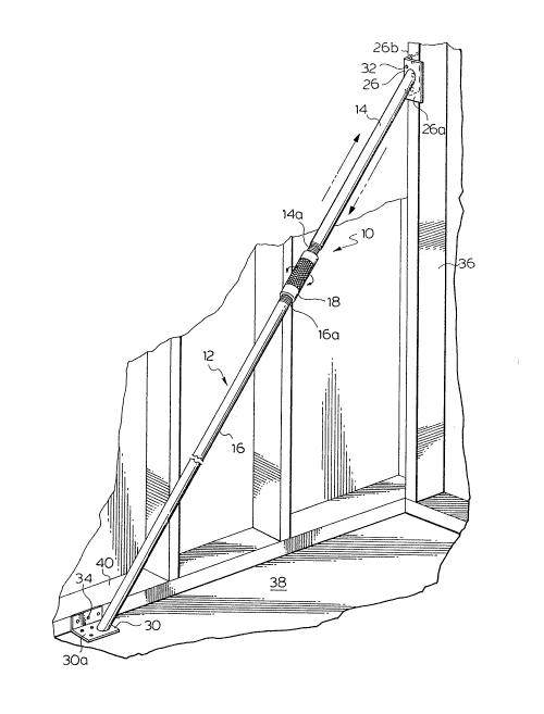
With reference to Figures l to 4, the adjustable brace,
indicated generally 10, comprises an elongated strut generally
12 made up of upper and lower tubes 14, 16 respectively inter-
connected by a coupling or turn-buckle 18. The exterior walls
14a, 16a of the tubes adjacent to the coupling are both
threaded but in opposite directions and mate with like
threads 19 formed on the interior wall of the coupling.
By rotation of the coupling in one direction, the tubes
will advance toward each other in the direction of arrows 20
in Figure 3 with resulting shortening of the length of the
strut. Rotation in the opposite direction produces a
lengthening of the strut in the direction of arrows 22 in the
same Figure. The coupling is intended to be rotated manually
and to facilitate that, its outer wall 24 is knurled as
illustrated in Figure 4.
2063n~
An anchor 26 is attached to the upper end of tube 14.
The anchor is made up of a short piece of angle-shaped
aluminum having first and second walls 26a,b disposed at right
angles to each other. The angle between the plane of the first
wall 26a to which the tube is attached and the longitudinal
axis of the strut (marked 28-28 in Figure 3) is preferably
about 30 degrees. A like anchor 30 is attached to the lower
end of tube 16 but the angle between the first wall 30a to
which the strut is attached and the longitudinal axis of the
strut is preferably about 60 degrees.
A number of apertures 32,34 ar~e formed in each anchor
26, 30 respectively for receipt of screws for removably
attaching the anchors to an upright member 36 of frame 37 and
to floor 38.
It is only necessary for one wall of each anchor to be
attached to an upright or to a floor. For example while Figure
2 shows one wall of the lower anchor 30 connected to the floor
while the other wall is connected to the lower member 40 of a
wall frame it is not necessary for the anchor to be connected
in ~his way. It is only necessary that the anchor be connected
to the floor. In most cases the lower anchor will not be
adjacent to a wall frame and can only be connected to a floor.
The strut will be properly connected in this way.
The strut is used to brace the frame of a wall after it
has been assembled. Usually the pieces of lumber which make up
2063~9~
the frame are resting on the Eloor while they are being
assembled. When the frame is fully assembled, it is raised
manually to the upright position. The lower anchor of the
strut is then placed on the floor and the upper anchor is
placed against the upright member of the frame as illustrated
in Figures 1, 2 and 5. When the walls of the anchors which are
connected to the struts are flush with the floor and the
upright, the strut is fastened in position by means of screws
in the manner illustrated in Figure 5.
The frame ls then plumbed by rotating the coupling to
le,ngthen or shorten the strut until the angle of the upright
is vertical as illustrated in Figure 1. A conventional
carpenter's level may be conveniently used to check the angle
of the upright.
The essential characteristics of the tubes which make up
the strut are structural strength or rigidity in both
compression and tension. The tubes must not sag when the
brace is connected to a frame. The preferred characteristics
of the tubes are lightness in weight to facilitate handling.
The tubes may be formed of tubular aluminum, magnesium or
reinforced plastic and may have an outer diameter of from
about 1 to 2.5 centimetres. The thickness of the walls of the
tubes can be from about 1 to 4 millimetres. Aluminum pipe
having an outer diameter of about 2 centimetres and an inner
diameter of about 1.5 centimetres makes suitable tubes. The
2063n9~
anchors may be formed of conventional angle-shaped aluminum
used in construction.
It is important that the anchors be rigidly fixed to the
strut. In that way the plane of wall 26a of the upper anchor
will always be normal to plane 30a of the lower anchor. If the
anchors can swivel or rotate relative to the struts the brace
will be damaged in use, possibly beyond repair. This is
because the anchors, if allowed to swivel, can be attached in
such a way that the planes of their walls 26a, 30a are not
normal to each other. If the coupling is rotated to shorten
the strut when the walls are thus, the two tubes will become
misaligned. The tubes will then bind in the coupling as it is
turned further with resulting damage to the threads of the
tubes or the coupling or of both.
There is another reason why the anchors should be
attached rigidly to the tubes. If they are, only one person
is usually needed to attach the strut in position to brace a
frame of a wall. The person grips the strut adjacent to the
coupling and places it in position to brace the frame. He
then adjusts it until the walls of the anchors are flush with
the floor and the frame. He can do this without changing the
position of his grip. Then, as illustrated in Figure 5, he
turns screws into each aperture in the anchors and into the
floor and frame using an electric drill in order to affix the
strut in position.
~3~
By contrast, if the anchors can swivel relative to the
tubes, two persons are usually needed to attach a strut in
position. One person is needed to hold the strut while the
other is needed to adjust the anchors until their walls are
flush with the floor and frame. One person cannot do both
since the anchors move independently of the brace and they
cannot be adjusted by the person who is holding the strut.
It will be understood of course that modifications can be
made in the preferred embodiment illustrated and described
herein without departing from the scope and purview of the
invention as defined in the appended claims.