Language selection

Search

Patent 2063128 Summary

Third-party information liability

Some of the information on this Web page has been provided by external sources. The Government of Canada is not responsible for the accuracy, reliability or currency of the information supplied by external sources. Users wishing to rely upon this information should consult directly with the source of the information. Content provided by external sources is not subject to official languages, privacy and accessibility requirements.

Claims and Abstract availability

Any discrepancies in the text and image of the Claims and Abstract are due to differing posting times. Text of the Claims and Abstract are posted:

  • At the time the application is open to public inspection;
  • At the time of issue of the patent (grant).
(12) Patent: (11) CA 2063128
(54) English Title: RAKE WITH WHEELS AND SWINGING COMB
(54) French Title: RATEAU A ROULETTES ET A PEIGNE BASCULANT
Status: Deemed expired
Bibliographic Data
(51) International Patent Classification (IPC):
  • A01B 1/14 (2006.01)
  • A01D 7/00 (2006.01)
(72) Inventors :
  • QUESNELLE, STELLA M. (Canada)
  • QUESNELLE, ALBERT A. (Canada)
(73) Owners :
  • QUESNELLE, STELLA M. (Canada)
  • QUESNELLE, ALBERT A. (Canada)
(71) Applicants :
(74) Agent: BORDEN LADNER GERVAIS LLP
(74) Associate agent:
(45) Issued: 1999-01-19
(22) Filed Date: 1992-03-18
(41) Open to Public Inspection: 1992-11-10
Examination requested: 1992-03-18
Availability of licence: N/A
(25) Language of filing: English

Patent Cooperation Treaty (PCT): No

(30) Application Priority Data:
Application No. Country/Territory Date
9110051.1 United Kingdom 1991-05-09

Abstracts

English Abstract


A rake is described, having wheels mounted rotatably
thereto which enable the rake to be moved easily from place to
place without lifting the rake from the ground. When the rake
is pulled towards the user, the comb is locked such that its
teeth are in the conventional operative position, i.e. pointing
downwardly, but when the rake is pushed away, the comb rotates
out of the way to permit the rake to be pushed easily, even over
piles of debris just raked.


French Abstract

L'invention porte sur un râteau auquel sont montées des roues, grâce auxquelles il est possible de déplacer le râteau sans le soulever du sol. Lorsque le râteau est tiré, la traverse se bloque de façon à placer les dents dans leur position opérationnelle classique, c'est-à-dire pointant vers le bas, mais lorsque le râteau est poussé, la traverse se rétracte, ce qui permet de pousser le râteau sans difficulté, même par-dessus des tas de débris tout juste râtelés.

Claims

Note: Claims are shown in the official language in which they were submitted.

THE EMBODIMENTS OF THE INVENTION IN WHICH AN EXCLUSIVE PROPERTY
OR PRIVILEGE IS CLAIMED ARE DEFINED AS FOLLOWS:


1. A rake comprising:
a elongated handle having an upper end and a lower end;
an axle mounted at the lower end of the handle, at a
right angle thereto;
a comb rotatably mounted on said axle, and having
raking teeth projecting downwardly therefrom;
wheels mounted at either end of said axle; and
stop means mounted to prevent rotation of said comb
beyond about 135 degrees from said handle.

2. A rake as recited in claim 1, in which said axle is
rotatable, being carried by a cylindrical sleeve rigidly mounted
at the lower end of the handle at a right angle thereto, said
wheels being rigidly mounted to the ends of said axle

3. A rake as recited in claim 2, in which said cylindrical
sleeve is secured to the lower end of the handle by virtue of
said handle having a bow at the lower end thereof, comprising two
arms extending downwardly and outwardly therefrom, said sleeve
being secured between said arms.

4. A rake as recited in claim 1, in which said stop means
are mounted to prevent rotation of said comb beyond about 90
degrees from said handle.
- 6 -

5. A rake as recited in claim 2, in which said stop means
are mounted to prevent rotation of said comb beyond about 90
degrees from said handle.

6. A rake as recited in claim 3, in which said stop means
are mounted to prevent rotation of said comb beyond about 90
degrees from said handle.

7. A rake comprising:
a elongated handle having an upper end and a lower end;
a bow/sleeve assembly secured to the lower end of the
handle, comprising a bow having two arms extending downwardly and
outwardly therefrom, and a cylindrical sleeve secured across the
ends of said arms;
a comb having cylindrical pieces secured to the upper
edge thereof and having raking teeth projecting downwardly
therefrom, said cylindrical pieces being adapted to align with
opposite ends of said cylindrical sleeve;
an axle passing through said cylindrical pieces and
said sleeve, and having wheels secured to opposite ends thereof,
whereby said comb is rotatable with respect to said handle and
bow;
said bow/sleeve assembly having at least one projection
therefrom to prevent rotation of said comb therepast.

- 7 -

Description

Note: Descriptions are shown in the official language in which they were submitted.


~3~.28

This invention relates to rakes.
With a conventional rake, the user must lift the rake
after each stroke to move it to the next location. Also, the
teeth of the rake tend to dig into the ground, which limits the
effectiveness of the rake. For elderly people in particular, ~ut
for anyone in general, these ~actors make raking an unnecessarily
; difficult and tedious process. Also, because of the tendency for
the teeth to dig into the ground, it is difficult to rake a
surface evenly.
It is an object of the invention to provide a rake
having wheels mounted rotatably thereto which enable the rake to
be mo~ed easily ~rom place to place without lifting the rake from
the ground. When the rake is pulled towards the user, the comb
is locked such that its teeth are in the conventional operative
position, i.e. pointing downwardly, but when the rake is pushed
away, the comb rotates out of the way to permit the rake to be
pushed easily, even over piles of debris just raked.
Further features of the invention will be described or
will become apparent in the course of the following detailed
description.
In order that the in~ention may be more alearly
understood, the preferred embodiment thereof will now be
described in detail by way of example, with re~erence to the
accompanying drawings and photograph copies, in which:
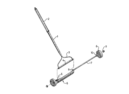
Fig. 1 is an exploded perspective view of the preferred
embodiment;
Fig. 2 is a front elevation view of the bow of the
preferred embodiment;

3~2~

Fig. 3 is side elevation view of the bow of the
preferred embodiment;
Fig. 4 is a front elevation view of the comb;
Fig. 5 is a side elevation vi~w of the comb;
Fig. 6 is a side elevation view showing the comb
rotated out o~ the operative position, i.e. where the user is
pushing the rake:
Fig. 7 is a side elevation view showing the comb in its
operative position, i.e. with teeth pointing down, where the user
is pul~ing the rake,
Fig. 8 is a perspective view showing the rake with the
handle flipped over to the other side, to form a carrying
plat~orm;
Fig. 9 is a side elevation view corresponding to Fig.
8.
In the preferred embodiment, the rake handle l, which
preferably has a sponge grip 2, has a generally Y-shaped bow
portion 3 secured thereto, projecting from the lower end of the
handle. A cylindrical sleeve 4 is welded or otherwise
permanently af~ixed across the lower ends of the two arms of the
~ow .
The comb portion 5 of the rake has two cylindrical
pieces 6 at each upper end, which align with the cylindriaal
sleeve 4 at either end thereof. An axle 7 is positioned~through
the cylindrical pieces 6 and sleeve 4, and wheels 8 are secured
on either end of the axle, via re~A;n;ng caps 9. WasherS 10 are
poKitioned between the cylindrical pieces 6 and the wbe-ls.


'
.

~ 3~2~
.
The comb is thus generally free to rotate on the axle.
Thus, as shown in Fig. 6, the rake is easily pushed forwardly
over debris 13 just raked. However, when the rake is pulled
towards the user, the ends 11 of the arms of the bow come into
contact with the comb, acting as stops to prevent further
rotation, thus in effect locking the comb in the operative
position. This is seen best in Fig. 7. In the pre~erred
embodiment, the stops are arranged to prevent rotation beyond
approximately ~0 degrees from the handle. It will be appreciated
that the angle is not critical. An angle of approximately 135
degrees could be used, for example, equating to teeth pointing
straight down and the handle angling upwardly at 45 degrees. The
angle o~ about 90 degrees has be~n found through experimentation
to be the optimum angle, although personal preference may have
a bearing, as may the exact nature of the raking work to be done.
Whatever the angle o~ the teeth, the wheels keep the
teeth 12 from digging into the ground 14, by maintaining the
appropriate spacing. The size of the wheels, or the length of
the teeth, must of course be matched generally so that the teeth
extend far enough, but not too far, into the ground. The extent
to which the teeth dig into the ground may be controlled by the
user, by varying the angle of the handle.
As seen in Figs. 8 and 9, the handle may be swung over
to the opposite side from the usual operational side. The comb
then forms a platform on which small items may be carried,~such
as an empty fruit basket 15 to carry small hand tools or raked
debris, or on which a larger item such as a garbage bag could be
balanced.


- 4 -


, ' .

2~3~ 2~

The features of the invention make it extremely easy
to use. No lifting is required. The rake merely needs to be
pushed over any debris, and then pulled back towards the user.
Because the teeth do not dig into the ground, more effective
5 raking can be achieved. Levelling loose earth is particularly
facilit~ted. The teeth also tend to be self-cleaning, since
pushing the rake ~orward tends to push debris o~f the teeth.
It will be appreciated that the above description
relates to the preferred embodiment by way of example only. Many
variations on the invention will be obvious to those
knowledgeable in the field, and such obvious variations are
within the scope of the invention as described and claimed,
whether or not expressly described.
For example, rotation o~ the comb could be provided ~or
in a number o~ other ways. A rigid axle could be used, for
example, with bearing-mounted wheels on either end thereof,
in~tead of a rotating axle as described above. The comb would
rotate about the rigid axle.


'
'

Representative Drawing
A single figure which represents the drawing illustrating the invention.
Administrative Status

For a clearer understanding of the status of the application/patent presented on this page, the site Disclaimer , as well as the definitions for Patent , Administrative Status , Maintenance Fee  and Payment History  should be consulted.

Administrative Status

Title Date
Forecasted Issue Date 1999-01-19
(22) Filed 1992-03-18
Examination Requested 1992-03-18
(41) Open to Public Inspection 1992-11-10
(45) Issued 1999-01-19
Deemed Expired 2002-03-18

Abandonment History

There is no abandonment history.

Payment History

Fee Type Anniversary Year Due Date Amount Paid Paid Date
Request for Examination $200.00 1992-03-18
Application Fee $0.00 1992-03-18
Maintenance Fee - Application - New Act 2 1994-03-18 $50.00 1994-03-14
Maintenance Fee - Application - New Act 3 1995-03-20 $50.00 1995-02-01
Maintenance Fee - Application - New Act 4 1996-03-18 $50.00 1996-02-15
Maintenance Fee - Application - New Act 5 1997-03-18 $75.00 1997-05-23
Maintenance Fee - Application - New Act 6 1998-03-18 $75.00 1998-02-26
Final Fee $150.00 1998-10-02
Maintenance Fee - Patent - New Act 7 1999-03-18 $75.00 1999-01-21
Maintenance Fee - Patent - New Act 8 2000-03-20 $75.00 2000-03-06
Owners on Record

Note: Records showing the ownership history in alphabetical order.

Current Owners on Record
QUESNELLE, STELLA M.
QUESNELLE, ALBERT A.
Past Owners on Record
None
Past Owners that do not appear in the "Owners on Record" listing will appear in other documentation within the application.
Documents

To view selected files, please enter reCAPTCHA code :


To view images, click a link in the Document Description column. To download the documents, select one or more checkboxes in the first column and then click the "Download Selected in PDF format (Zip Archive)" or the "Download Selected as Single PDF" button.

List of published and non-published patent-specific documents on the CPD .

If you have any difficulty accessing content, you can call the Client Service Centre at 1-866-997-1936 or send them an e-mail at CIPO Client Service Centre.


Document
Description 
Date
(yyyy-mm-dd) 
Number of pages   Size of Image (KB) 
Cover Page 1993-11-12 1 27
Abstract 1993-11-12 1 16
Claims 1993-11-12 2 69
Drawings 1993-11-12 4 124
Description 1993-11-12 4 151
Cover Page 1999-01-08 1 38
Representative Drawing 1999-01-08 1 7
Correspondence 1998-10-02 1 40
Fees 1997-05-23 8 283
Fees 1999-01-21 1 32
PCT Correspondence 1994-07-20 1 30
Fees 1996-02-15 1 29
Fees 1995-02-01 1 27
Fees 1994-03-14 1 20