Note: Descriptions are shown in the official language in which they were submitted.
2~161
The present invention relates to downhole drilling
tools and more particularly t~ an adjustable bent housing or
sub useful in the directional drilling of well bores.
BACKGROUND OF THE INVENTION
"Bent housings" or "subs" are commonly used in well
drilling in order to deviate the borehole from vertical to a
desired angle. "Housings" are short threaded sections o~
drill pipe. They are "bent" eithler by physical bending or
machined to create an angular of f set between the respective
lo ends of the housing. When the bent housing is placed in the
drill string, the bend in the housing causes the drill string
to deviate from vertical as drilling progresses. One drawback
in the use of bent housings is that the angle is fixed. This
means that numerous bent housings must be kept at the drill
site to provide a selection of a range of angles which may be
required as drilling progresses. The trend in the industry
has, therefore, been to develop a single bent housing on which
the angle can be adjusted. The angle of the present housing
is adjusted prior to insertion into the well, and remains
fixed until withdrawn and readjusted. Housings of this type
are therefore referred to as "surface adjustable" bent
housings, to distinguish them from housings that are "downhole
adjustable'l, that is, adjustable while in the well bore
without being withdrawn to the surface.
Although the terms "subs" and "housings" are
sometimes used synonymously, a "sub" is typically a bent
section installed in the drill string above the downhole
motor/bearing assembly/drill bit combination used in the
directional drilling of well bores. A "housing" on the other
hand fits between the motor and the bearing assembly and in
addition to providing bend, it also accommodates a drive shaft
connecting the motor to the bearing assembly/drill bit through
its central bore. The present invention is intended for use
primarily as an adjustable bent "housing".
.
~3~ 61
2 ,
SUMMARY OF THE INVENTION
The present i~vention represents an alternate
structure for an adjustable bent housing.
According to the present invention, there is
provided an adjustable bent housing, comprising a cylindrical
housing having a first uphole and a second downhole end and
a bore formed therethrough, the bore being divided into uphole
and downhole portionsl the portions being axially offset to
one another, a tubular mandrel having a first uphole end and
.0 a second downhole endl the ends being axially offset to one
anotherl the downhole end of the mandrel being receivable
along a portion of its length into the uphole portion of the
bore for rotational movement relative to the cylindrical
housing for varying the angle of bend between the mandrel and
the cylindrical housing, and locking means comprising a first
outer and a second inner concentric sleeve disposed annularly
about the mandrel, the inner sleeve being axially movable
relative to the mandrel in response to rotation of the outer
sleeve between a first locked position wherein engagement
means provided at one end of the inner sleeve are moved into
contact with cooperating engagement means provided on the
cylindrical housing and mandrel to prevent relative rotation
therebetween, and a second unlocked position in which the
engagement means disengage the cooperating engagement means
on at least one of the mandrel or cylindrical housing to
permit relative rotation therebetween.
According to a further aspect of the present
- invention, there is also provided an adjustable bent housing -:
comprising a tubular mandrel having an uphole and a downhole
end with radially outwardly extending splines formed adjacent
the downhole encl, the tubular mandrel having a bend of a
predetermined angle formed therein, a cylindrical housing
having a bore formed therethrough between a downhole and an
up~ole end of the cylindrical housing, the uphole end of the
bore having radially inwardly extending splines formed
. .
.
2 ~
thereon, the bore having a bend o~ a predetermined angle
formed therein, the downhole end of the tubular mandrel being
concentrically receivable within the uphole end of khe
cylindrical housing to be rotatable~ relative thereto to vary
the angle of the bent housiny in response to the rotation, and
locking means disposed annularly around the downhole end of
the tubular mandrel between the uphole ends of the cylindrical
housing and mandrel, the locking mealns including a first inner
sleeve axially movable between a first locked and a second
lo unlocked position in response to rotation o~ a cooperatively
associated outer sleeve, the inner sleeve including a spline
section thereon to engage the splines on the cylindrical
housing and the mandrel when in the locked position to prevent
relative rotation between the cylindrical housing and mandrel,
and to disengage the splines on at least the cylindrical
housing when in the unlocked position to permit the relative
rotation between the cylindrical housing and mandrel.
Preferred embodiments of the present invention will
now be described in greater detail, and will be better
understood when read in conjunction with the followiny
drawings, in which:
Figure 1 is a partially cross-sectional elevational
view of the bent housing described herein;
Figure 2 is an enlarged elevational view of a part
of the bent housing of Figure 1 representing the locking
means; and
Figure 3 is an exploded, perspectiva view of the
bent housing of Figure 1.
DETAILED DESCRIPTION OF THE PREFERRED EMBODIMENTS
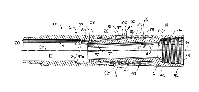
With reference to Figures 1 and 2, adjustable bent
housing 10 for use in directional well drilling generally
comprises a tubular offset housing 12 and a tubular offset
mandrel 14 located in the uphole direction from housing 12.
Genera].ly speaking, it is desirable that bent
housing 10 be adjustable to provide 2 to 3 of total bend
2 ~ 6 ~
relative to the longitudinal axis 21 of ho~lsing 12. When
viewed externa].ly, housing 12 is symmetrical about its
longitudinal axis 21, which axis will deviate up to a maximum
of 3 (i.n the embodiment shown herein) relative to the
longitudinal axis ~f the drill str.ing or downhole motor (not
shown) connected to mandrel 14 by m~ans of threaded connection
28.
One-half, equal to 1~1/2, of the bent housing's
total adjustable offset is provided by the angled porkion of
bore 17 of housing 12. Bore 17 includes a non-angled downhole
portion 17d extendiny from downhole end 20 of housing 12 to
the intermediate points marked x and y in Figure 1 which is
axially aligned and centred within the housing. Uphole of x
and y, extending to the uphole end 22 o~ the housing, an
uphole portion 17u of bore 17 is formed at an angle of 1-1/2
relative to downhole bore 17d and to the longitudinal axis of
housing 12.
The remaining one-half of the housing's total bend,
which in the case of the embodiment shown in the drawings is
again 1-1/2, is provided by mandrel 14. Mandrel 14 comprises
a cylindrical tubular barrel 40 and a tubular stinger 38. The
mandrel as a whole is preferably machined as a single piece,
with barrel 40 including at its end 42 a female threaded
connection 28 used to connect the housing to the end of a
downhole motor of the sort used for the directional drilling
of oil wells.
Barrel 40 is symmetrical about the mandrel's
longitudinal axis, but stinger 38 is machined at an angle of
1-1/2 relative to the barrel, the offset being measured from
bend point "a". The offset is identified in Figure 1 as angle
B. Stinger 38 is otherwise symmetrical about its longitudinal
axis 32 except internally at 51 where its inner diameter
widens out into the inner diameter of barrel 40.
As shown in Figure 1, stinger 38 is telescopically
received into bore 17u of housing 12 so that its longitudinal
.
' ~ .
2~3 ~ ~
axis is parallel and coaxial with the longitudinal axis of
bore 17u. As illustrated in Figure 1, the mandrel is inserted
so that its 1-1/2 deflection is exactly offset by the 1-1/2
deflection of bore 17u. The long:itudinal axis 46 of barrel
540 and the longitudinal axis 21 of housing 12 are therefore
aligned so that housing 10 as a whole is perfectly straight.
It will be appreciated that if the housiny's total
adjustable bend is not divided equally between the mandrel on
the one hand and the housing on the other hand, a complete
offset of the two angles will not be possible, with the result
that the housing will always possess a predetermined amount
of bend depending upon the apportionment of the offset between
the mandrel and the housing.
If the mandrel and housing are rotated relative to
each other by 180, the two offsets described above will
complement each other to provide a total cumulative bend in
the housing of 3 measured from point "a". More specifically,
longitudinal axes 46 and 21 will intersect sach other at point
"a" at an angle of 3. A further 180 relat~ve rotation of
the mandrel and housing will again bring the total bend in the
housing to 0 to thereby straighten the tool.
It is desirable that the amount of bend in the
housing be incrementally adjustable, and that means be
provided to lock the housing at a predetermined bent angle and
to prevent accidental or unintentional changes to the
housing's bend when in use downhole.
This requires that means be provided to non-
rotatably connect mandrel 14 to housing 12 when the housing
is in use to prevent relative rotation therebetween. These
means must however be releasable to permit such rotation when
it is desired to change or adjust the housing's bend.
With reference particularly to Figure 2, locking
means 63 comprise a plurality o~ circumferentially spaced
apart elongated splines 65 formed on the outer surface of
35 ~ stinger 38, a plurality of circumferentially spaced apart
.
7 : : . :
' . ,', " ` ' ~ ~ :
2~3161
elongated splines 71 formed on the inner surface of housing
12 at the uphole end 22 thereof, a spline sleeve 60 and a
locking sleeve 55. Spline sleeve 60 includes a set of
circumferentially spaced apart elongated splines 6~ formed on
its inner surface to engage splines 65 on the mandrel and
another set of circumferentially spaced apart elongated
splines 72 formed on its outer surface to engage splines 71
on the housing as will be described in greater detail below.
All of the housing's splines are elongated in the longitudinal
direction of stinger 38, and extend either radia].ly inwardly
or outwardly from the surfaces on which they are ~ormed, as
the case may be. Splines 71 are chamfered at their uphole
ends 69 as seen most clearly from Figure 3. This facilitates
the meshing of splines 71 and 72.
Splines 64 and 65 fit slidably closely in an
interfingering relationship, as do splines 71 and 72 when the
housing is locked.
In Figures 1 and 2, housing 10 is shown for
comparative purposes in both its locked and unlocked
(ad~usting) position. Above the centre line (axis 21), the
housing is shown with locking means 63 in the unlocked
position thereof permitting relative rotation between the
housing and mandrel for adjustment to the tool's bend. Below
the centre line, the tool is shown in the locked position in
which the housing and mandrel can no longer rotate relative
to each other. As will now be described in greater detail,
spline sleeve 60 can be moved between its locked and unlocked
positions by rotating locking sleeve 55 in a counterclockwise
or clockwise direction.
Spline sleeve 60 includes a smooth internal bore 70
to facilitate reciprocating sliding movement along stinger 38,
an externally threaded portion 76 and an enlarged flange
bounded by shoulders 61 and 62. Cooperating locking sleeve
55 is internally threaded at 56 to engage threads 76 on the
spline sleeve and similarly includes a shoulder 57 to abut
3 ~ 1
ayainst shoulder 62 when the housing is unlocked. In
addition, locking sleeve 55 is dimensioned to be retained
between the uphole end 22 of housing 12 and shoulder 47 on
mandrel barrel 40.
With reference to the lower half of Figure 2 beneath
the centre line, housing 10 is locked by rotating locking
sleeve 55 in the counterclockwise direction to move spline
sleeve 60 in the downhole direction as indicated by arrow A.
The rotation of the locking sleeve continues until shoulder
61 of the spline sleeve abuts against uphole end 22 of housing
12. In this position, splines 71 and 72, and 64 and 65,
respectively, are fully engaged to prevent relative rotation
between the mandrel and the housing. Sleeve 55 is then
torqued tight to prevent the spline sleeve from loosening and
to hold the entire housing as a rigid unit. When the housing
is thusly locked, uphole end 54 of sleeve 55 compressively
abuts against shoulder 47 of the mandrel to form a metal-to-
metal seal.
To adjust the bend of the hvusing, the locking
sleeve is rotated clockwise to move spline sleeve 60 in the
uphole direction indicated by arrow B in the upper half of
Figure 2 above the centre line. The rotation of the locking
sleeve continues until shoulders 62 and 57 abut to prevent
further rotation, thereby indicating that splines 71 and 72
are now fully disengaged. Mandrel 14 is now freely rotatable
relative to housing 12 to adjust the angle of the housing's
bend. Splines 65 are sufficiently elongated to remain meshed
with splines 64 even with the locking sleeve in this position
so that the locking sleeve is rotated with the mandrel. If
there are 24 of each of splines 71 and 72, the possible
settings for the housing's band are, incrementally, 0, .391,
.776, 1.1~7, 1.500, 1.826, 2.1~1, 2.379, 2.598, 2.7711,
2.897, 2.974, 3.000 and further identical increments back
to 0. After the desired amount of bend has been selected,
the housing is then locked into its new setting in the manner
-
. , ' ' ' ' ,
2 ~
described above. Calibrations (not shown) are provided on the
outer surfaces of the mandrel and housing to provide an
externally readable indication of the amount of bend dialed
into the tool before the locking sleeve is rotated to re
engage splines 71 and 72 to set the tool at the new bend.
Housing 12 is held to mandrel 14 by means of a
mandrel nut 48 and a retaining ring 37. Stinger 38 is
threaded at its downhole end 39 to engage the correspondingly
internally threaded mandrel nut 48. Nut 48 is torqued tight
to compress retaining ring 37 between nut 48 on the one hand,
and the downhole ends of splines 71 and 7~ and a shoulder 84
in the stinger just below splines 71 to secure the mandrel and
housing together and to prevent longitudinal movement between
these two components.
To assemble the housing, mandrel nut 48 is first
inserted into bore 17u as far as it will yo. Retaining ring
37 is then inserted into the housing by sliding it sideways
through the gaps between splines 71 and is then rotated 90
to seat against the downhole ends of splines 71. The mandrel
nut is then moved in an uphole direction to seat against ring
37. The mandrel is inserted and the mandrel nut is then
torqued tightly onto the mandrel using a wrench (not shown)
inserted through the downhole end 20 of housing 12 to engage
notches 87 provided for this purpose in the rearward end of
the nut. Once the nut is torqued onto the mandrel, a snap
ring 89 may be installed to positively prevent any loosening
of the mandrel nut.
A grease plug 91 is provided in the housing to add
grease for lubrication of the housing's internal splines and
threaded mechanisms and to prevent drilling mud from entering
these parts of the tool. Splines 71 each include a shallow
rearward extension 73 which spaces ring 37 from the inner
surface of bore 17u, and the gaps between these shallow
extensions allows the grease to migrate from cavity 94
surrounding the mandrel nut into the spline mechanisms and
: . .
~Q~ 6~
into cavities 95 and 96 between stinger 38, spline sleeve 60
and locking sleeve 55. Passageways 97 and other passages (not
shown) allow the grease to reach these cavities and other
places internally of the housing where it's needed. Whan
locking collar 55 is torqued to lock the housing, the grease
is sealed inside the tool to prevent or at least to minimize
the ingress of drilling mud into the splines and threads.
As will be appreciated by those skilled in the art,
drilling mud will be pumped under considerable pressure
through the interior of housing 10, including the housing and
mandrel, to the drill bit (not shown). The mud will return
to the surface through the annulus between the drill string,
and the inner surface of the well bore. It is important that
mud not escape through any of the housing's joints as this
will cause a loss of circulation at the bit, in which event
the entire string must be removed for repairs to the housing,
causing considerable delay and expense. Similarly, it is
desirable to prevent mud from the annulus from getting into
the housings internal threads and splines. The present
housing uses various seals to prevent the escape or incursion
of mud.
Commencing at the uphole end o~ the housing, a
metal-to-metal seal is formed between end 54 of locking sleeve
55 and the abutting portion of mandrel shoulder 47 when the
housing is locked to prevent the entry of mud at this point.
When sleeve 55 is torqued to lock the housing, there will be
a slight gap or at least a loose fit between the downhole end
of this sleeve and the end 22 of housing 12 through which mud
can enter. Sealing between sleeves 55 and ~0 between
shoulders 61 and 62 to prevent mud from entering cavity 95 and
threads 56 and 76 is provided by an o-ring 106. The metal-to-
metal seal between shoulder 61 and end 22 o~ housing 12 seals
against mud entering splines 71, 72 and cavity 94. Sealing
between mandrel nut 48 and stinger 38 just downhole of the
threaded connection between the nut and stinger is provided
", - - ,
6 ~
by another O-ring 107. A po]ypak seal lOB provided in a
circumferential yroov~ llo formed in nut 48 seals the
interface between nut 48 and angled housing bore 17u.
To protPct the outer surface of housing lo from
excessive wear, tungsten carbide buttons 113 may be press-
fitted into holes 114 formed circumferentially about the outer
surface of mandrel 14 as shown, and a shallow tungsten carbide
hard facing may be applied in bands about th~ outer surface
of housing 12.
Adjustments to the housing's bend are usually made
at the surface. Housing 12 may be clamped in the derrick's
rotary table and the locking sleeve can then be operated using
the rig's power tongs. The rotary table can then be used to
rotate the housing's housing or the tongs can be used to
rotate mandrel 14 in order to dial in the required bend as
read from the calibrations provided on the housing's outer
surface. The tongs are then used to tighten the locking
sleeve to re-engage the splines 71 and 72 and lock the housing
for use downhole.
Some of the advantages enjoyed by the present
housing over earlier designs include the lack of any loose
parts on the exterior of the housing that require removal for
adjustments to the tool or that could become lost downhole.
Moreover, the length of the housing remains constant and does
not change when the housing is either locked or unlocked to
make adjustments to its bend. The housing's overall design
minimizes the number of required parts which lowers its
manufacturing costs, and the tolerances between parts are less
critical than is the case with a number of prior art housings,
and this again ~acilitates manufacture at a lower cost. By
varying the number and size of the splines and the offset
angles of the mandrel and the angled bore of the housing, the
housing can be manufactured in different versions depending
upon the total amount of bend to be provided.
~3~.6~
11
It will be apparent to those skilled in the ark that
modifications may be made to the preferred embodiment
described herein without departing from the spirit and scope
of the spirit and scope of the invention.
'
' ' ~ ' " . . .' ~ ' :
;. .
.
. .