Note: Descriptions are shown in the official language in which they were submitted.
2 ~ ~ 3 7 ~
1 62739-254
The present invention relates to temperature-controlled
.-
spaces, such as envixonmental chambers and, in particular, to acontrol system for controlling the temperature of such a space.
U.S. Patent No. 5,226,472 describes a modulated
temperature control system which simultaneously controls the
,. r.
heating and refrigeration units ln opposite directions ~-
substantially continuously between minimum and maximum heating and
cooling conditions. However, that system utilizes an electronic ` ;~
suction throttling valve whlch requires an expensive modulation -~-
circuit to modify the control signal so that it is suitable for
application to the throttling valve.
Summary of the Invention
It is a general object of the pre6ent invention to
provlde an improved temperature control system for a served space
which avoids the disadvantages of prior control systems while
affordlng additional structural and operatlng advantages.
An important feature of the invention ls the provision
of apparatus for controlling ~he air tempera~ure of a served space
by simultaneous control of heating and refrigeration units in ; ;~
opposite directions substantially continuously between minimum and
maximum heating or cooling conditions.
In connection with the foregoing features, another
feature of the invention is a provision of apparatus of the type
set forth which utilizes the same control signal for effecting - `~
control of both the heating and refrigeration units.
-: - . . -i . -.
. .', ,' " -..-.
6 3 7 ~
Yet another feature of the invention is the provision
of an apparatus of the type set forth, which is o~
relatively simple and economical construction. : ~ :
These and other features of the invention are attained
5 by providing in an apparatus for controlling the air ;~
temperature of a served space which is equipped with a
heating unit and a refrigeratlon unit, including a
thermostat which sen es the temp~rature in the served space
and generates a con~rol signal indicative of the dif~erence
between the sensed temperature and a predetermined set point
temperature, the improvement comprising: valve means in the -
refrigeration unit for controlling the flow of refrigerant -:~
therethrough, drive means for the valve means for effecting
continuous control thereof between fully open and fully
15 closed conditions, relay means coupled directly to the ~ ;
thermostat, and power supply means coupled through the relay
means to the heating unit and to the drive means for
powering same, the relay means being responsive to the
control signal ~or controlling the operation of the heating
unit and the refrigeration unit in a push-pull manner such
that the amount of cooling provided i5 inversely
proportional to the amount of heating providing. .
The invention consists of certain novel features and a
combination of parts hereinafter fully described,
25 illustrated in the accompanying drawings, and particularly ~;
pointed out in the appended claims, it being understood that
various changes in the details may be made without departing
from the spirit, or sacrificing any of the advantages of the `:~
present invention.
rief Descri~tion of th~ Drawin~s
For the purpose of facilitating an understanding of the
invention, there is illustrated in the accompanying drawings
a preferred embodiment thereof, from an inspection of which,
when considered in connection with the following
description, the invention, its construction and operation,
¦ and many of it~ advantages should be readily understood and .`
'~
2~6370~
appreciated.
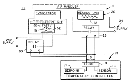
FIG. 1 is a partially schematic and partially ~unc~
tional block dlagrammatic illu tration o~ the temperature
control system of the present inv~ntion;
FIG. 2 iB a fluid-flow schematic diayram of the refrig~
eration unit of the temperature control system of FIG. 1;
FIG. 3 is a wavefvrm diagram illustrating the signal at
the output of the temperature controller 15; and
FIG. 4 i~ a graph illu~trating the heating and cooling `
power outputs of the temperature control system of FIG. 1.
Description of the Preferred Embodiment
Referring to FIG. 1, there is illustrated a temperature
control system, generally designated by the numeral 10, ~ i
constructed in accordance with and embodying the features of
the presQnt invention.
The temperature control system 10 i8 of the type which
may be used for controlling the temperature in a served
space, such as an environmental chamber, and includes an air
handler 11 for controlling the flow of air through the
20 served space. The temperature control system lO includes a ;~
thermostat or temperature controller 15, which may be a
microprocessor-controlled device, such as that sold by
Eurotherm Corporation under the model number 808. The
temperature controller 15 includes a sensor 16 for sensing
the temperature of the air in the served space, a set point
control unit 17 for setting the predetermined temperature
which is to be maintained in the served space, and a
comparator 18 which receives the inputs from the sensor l~
and the set point control unit 17 and generates on output
terminals 19 a pulse-width-modulated ("PWM") signal which is
indicative of the difference between the set point
temperature and the actual sensed temperature.
The temperature control system 10 also includes a
heating unit 20 and a refrigeration unit 30 for,
respectively, heating and cooling the air in the served
space. The heating unit 20 preferably includes a resistance
., .. , ~. .. .
,~ ' ' ' ~.,, .'
2 ~ ~ 3 7 ~
heater 22 which is dispos~d in the air s~ream of the air
handler 11 of the served space and is connected across an
associated power supply 24 through ths normally-open
contacts of a solid state relay 25. The control terminals ~ ;
of the relay 25 are connected to the output terminals 19 of
the temperature ¢ontroller 15 for closing the relay contacts
when the PWM output signal from the comparator 18 is high,
as will be explained more fully below.
Referring also to FIG. 2, the refrigeration unit 30 is
largely of conventional construction, including a
compressor, a condenser and an evaporator interconnected by
associated conduits. More specifically, the refrigeration
unit 30 includes a compressor 31, the output of which is
coupled through a T-fitting 32, one branch of which is -
coupled via a refrigerant line 33 to a first port of a four-
way valve 34. The line 33 is coupled to the input of the
compressor 31 through a dual pressure control unit 35 which
monitors the pressures at the input and the output of the ;~
compressor 31 in a known manner. A second port of the four~
way valve 34 is coupled by a refrigerant line 36 to the
input of a condenser 37, the output o~ which is coupled
. . ~, .
through the bypass port of a thermal expansion valve 38 and
a check valve 39 to a receiver 4Q. The output of the - `-
receiver 40 i5 coupled through another check valve 41, a
filter drier 42, a sight glass 43, a solenoid valve 44, a
pair of T-fittings 45 and 46, and a thermal expansion valve ~ `~
47 to the input of evaporator coils 48, which are located in
the air stream of the air handler 11 of the served space.
An external equalization line 49a is provided around the
. ~
evaporator coils 48 between the output thereof and the
thermal expansion valve 47. Also located on the output line
from the evaporator coils 48 is a temperature sensing bulb
49 for controlling the operation of the thermal expansion
valve 47 in a known manner.
The output of the evaporator coils 48 is also coupled
to the input of an electrically powered, thermally or heat
': ': ,.~,....
" ,,~ " ~,...
--~' ~-.' .
2~3~
motor activated suction throttling valve (9ITASTVll) 50, which ~ :
is a normally-open, heater-operated valve, which may be of ~ :
the type sold by ALC0 Company under the trade designation
"PETR". The TASTV 50 include~ a heating el~ment 51 which
operate6 a bimetallic motor 52. The TAS~V 50 is typically
also provided with an external electronic~s package to
modulate the valve and a temperature sens.ing probe to :~:
monitor return air, but neither o~ these latter features is
used with the present invention, since the T~STV will be
10 controlled by the temperature controller 15, as will be : :
explained more fully below. ~he TASTV 50 operates
substantially continuously between fully-open and fully~
closed conditions, and operates by responding to the
pulsating voltage at the output of the te~perature
controller 15, as explained below. The output of the q'ASTV
50 is coupled by a line 53 to a third port of the four-way : .
valve 34, a fourth port of which is coupled via a line 54,
T-fittings 55, 56, 57 and 58 and a crankcase pressure
regulator valve 59 to a suction accumulator 60 which is, in
20 turn, coupled to the input of the compressor 31. Located on ;~
the compressor input line are temperature sensing bulbs 61
and 62, the latter controlling the thermal expansion valve
38. An external equalization line 63 is also connected
around the compressor 31 between the T-fitting 58 and the
thermal expansion valve 38 through a solenoid valve 64.
There is also provided a hot gas bypass line 65 which
is coupled between the output and the input of the .
compressor 31. More ~pecifically, the hot gas bypass line
65 is coupled from the T-fitting 32 through a hand valve 66, -~
30 a solenoid valve 67 and a capacity valve 68 to the T-fitting ..
55, an external egualization line 69 being provided for the
capacity valve 68. The solenoid of the solenoid valve 67 is
controlled by a temperature control unit 74 which is coupled
to the input of khe compressor 31. The temperature control
sy~tem 10 also includes a refrigeration bypass line 70,
which is coupled from the T-fitting 45 through a solenoid - `
..
`. ',"' ` '. `..~ ''
-` :'`~'~"
2 ~ ~ 3 ~ 0 ~
valve 71 and a thermal expansion valve 72 to the T-fitting
56. The thermal expansion valve 72 is controlled by the
temperature sensing bulb 61 and i5 provide~d with an ex~ernal
equalization line 73 coupled to the T-fitting 57.
In operation, the hot gas bypass line 65 serves to
maintain adequ2te input pressure to the ¢ompres or 31.
Thus, for example, when the TASTV 50 reaches a nearly fully ~ ~-
clo~ed condition, the pressure at the input of the -~
compressor 31 ~ay drop to a predetermined minimum pressure.
This drop in pressure will be sensed by the capacity valve
68 via the line 65 which is coupled to the input of the ~ s
compressor 31, thereby causing the capacity valve 68 to be
opened to bypass hot gas from the output of the compressor
31 back to its input without going through the condenser 37.
This maintains the compressor input pressure above the
predetermined minimum value for which the capacity valve 68
has been set. If the temperature at the input of the ~ -
compressor 31 becomes too high, the signal from the sensing
bulb 61 will further open the thermal expansion valve 72 to
increase the flow of cold refrigerant from the output of the
receiver 40 directly to the input of the compressor 31 via ~ s-~
the line 79 without going through the evaporator coils 48,
thereby to maintain the temperature at the input of the -
compressor 31 at or below a predetermined maximum `~ -
25 temperature. As a ~urther ~afety feature, if the ~ i~
temperature at the input of the compressor 31 reaches a ~
higher predetermined temperature, the temperature controller -``~ ;
74 will actuate the solenoid of the solenoid valve 67 to --
close the valve 67 and prevent the flow of hot gas through
30 the capacity valve 68 in the hot gas bypass line 65. `~
It will be appreciated that, in normal operation, the ;- -~
compressor 31 is substantially continuously operating. ~ -
However, if the temperature at the input of the compressor
31 becomes too high or too low, it will be automatically
35 shut off by associated control circuitry (not shown) in a ~~
known manner, although the refrigerant b~pass line 70,
".
~::
:
2~3~
described above, is d~signed to prl3v~nt high-temperature -~
shut off. It will also be appreciated th,at the compressor
31 is designed to automatically ~hut off if th~ input
pressure becomes too low or the output prlessure becomes too
high but, as was indicated above, the hot ya~ bypass line 65
is design~d to prevent low-pressure ~hut ~Dff of the
compressor 31.
In normal opera~ion, the rerrigerant flow is from the
output of the compressor 31 through the line 33, the fsur~
way valve 3~, the line 36 and the condenser 37, and thence
through the bypass port of the thermal expansion valve 38
and the receiver ~0 to the thermal expansion valve 47 and
the evaporator coils 48 ~or cooling the air in the served
space. The evaporated refrigerant then flows through the
TASTV 50 back through the four-way valve 34, the line 54 and
the accumulator 60 to the lnput of the compressor 31 for
repeating the cycle.
It will be appreciated that if the air temperature at;~
the evaporator coils 48 ~rops below freezing, the water
20 vapor in the served space will freeze on the coil surfaces, -~
so the temperature control system 10 is also designed to
operate in a defrost mode. In this event, the four-way
valve 34 switches to reverse the flow of refrigerant through
the system. More specifically, in the defrost mode, the
compressor output line 33 is coupled to the line 53 and the
condenser line 36 is coupled to the compressor input line
54. Thus, it will be appreciated that, in the defrost mode,
the compressed refrigerant passes through the TASTV 50 and
then in a reverse direction through the evaporator coils 48,
30 which act as a dondenser, thence thrsugh the bypass port of ~-
the thermal expansion valve 47 and a check valve 75. The ~ ~-
refrigerant then flows through a bypass line 76 around the -
receiver 40 through the thermal expansion valve 38 and in a
reverse direction through the condenser 37, which acts as an -~
35 evaporator, then back through the four-way valve 34 and the ` ; ;
line 54 to the input of the compressor 31. ~ -~
,, .,. , , ~ ..... .. .
2 0 6 3 7 ~
Referring now to FIGS. 1 and 3, the temperature cont~ol
system 10 also include~ a solid state relay 80 which i5
coupled to the output terminal l9 of the temperature
controller 15. A ~uitable pow~r supply 8:L, whiah may be a
24-volt supply, is connected through the normally-open
contacts of the relay 80 to the heating e:Lement 51 of the
TASTV 50.
In operation, to effect control o~ the TASTV 50, the
output signal from the temperature contro:Ller 15 is a PWM
10 signal 105 (FIG. 3) which has a high level 106 at ~ -
substantially ~5 volts and a low level 107 at 0 volts and is
set to have a period or cycle time o approximately one
second between adjacent low-to-high transitions. The signal
105 is illustrated with a 50% duty cycle, for purposes o~
discussion, but it will be appreciated that the duty cycle
may vary between 0 and 100%, depending upon the difference
between the sensed temperature in the served space and the ~ - :
set point temperature. -~-
In overall operation, when the temperature controller
20 15 detects a difference between the sensed temperature and -
the set point temperature, it will change the duty cycle of ;-
the PWM output signal 105 accordingly. Thus, if the sensed
temperature i8 too low, the duty cycle of the PWM signal 105
will be increased, thereby effectively increasing the ;
25 heating output o~ the heating unit 20. More specifically, `- -
whenever the output signal 105 is high, the contacts of the
relay 25 will close, turning the heater 22 on. Thus, the ,
greater the duty cycle of the PWM waveform, the greater the
percentage of time during each cycle that the heater 22 will
be on and, correspondingly, the greater the overall heating
output. Accordingly, it will be appreciated that the
heating output from the heating unit 20 can be substantially
continuously varied between a minimum heating output, which
is substantially 0 when the PNM waveform 105 has a zero duty -
cycle and the heater 22 is continuously off, and a maximum
heating output of substantially 100%, when the PWM waveform
~0~3~
g
105 has a 100% duty cycle and the heater 22 i~ continuously
on. Thi~ variation i5 illustratQd by the curve 110 in FIG.
4.
It ia a fundamental aspect of the prlesent invention ~-
that the PWM signal 105 which control~ thle heating unit 20
simultaneously effects a corresponding, but inverse control
of the refrigeration unit 30 60 that, as the heating output
is increased the cooling output is corres]pondingly
decreased, and vice versa. Thus, in the event that the
10 sensed temperature is too low, ~.g., the temperature control :~ -
system 10 will compensate by not only increasing the heating
output but also by simultaneously decreasing the cooling
output, for more rapidly bringing the temperature of the ~ ~-
served space into regulation at the set point temperature.
The TASTV 50 is normally in a fully opened condition,
accommodating maximum refrigerant flow through the
evaporator coils 48 and, accordingly, maximum cooling
output. Whenever the output signal 105 from the temperature
controller 15 is high, the contacts of the relay 80 will - ~`
20 close, turning on the heating element 51 of the TASTV 50. - ~ ` -
Thus, the greater the duty cycle of the PWM waveform, the
greater the percentage of time during each cycle that the
heating element 51 will be on and, correspondingly, the j~
greater the heating output therefrom. As the heat from the
25 heating ale~ent 51 increases, a bimetallic motor 52 in the i;
TASTV 50 re~ponds to close the TASTV 50, thereby reducing
the flow o~ refrigerant through the evaporatvr coils 48 and,
thereby, correspondingly reducing the cooling output. In
like manner, as the duty cycle of the PWM waveform 10~
- ... . ... ~; . ~
decreases, reducing the heating output of the heating unit
20, the voltage applied to the TASTV heating element 51 also ~-
decreases, further opening the TASTV 50 to increase the
cooling output.
~his "push-pull" type of operation is illustrated in
35 FIG. 5, wherein it can be seen that a decrease in the ~ P~
heating output curve 110 results in a corresponding increase
2 0 ~ 3 7 ~
; . .,, ~. --..
: ' '~
in the cooling output curve ~11. WhQn each o~ the heating
unit 20 and the refrigeration unit 30 are producing about
50% of their maximum output, the curves 110 and 111
intersect substantially along the 50S h~ating and cooling
level 113.
Modern microprocessor-based temperature controllers,
such as the ~urotherm Model 808 ~entioned above, provide
superior PID (proportion-integral-derivative) algorithms for
enabling precision proportional throttling back of applied
power as the set point temperature is reached, automatic
reset to eliminate proportional droop and rate control to -~
correct for set point overshoot. These algorithms have
heretofore been used only to control heating. The present ` ~ :
invention synchronously modulatRs cooling inversely
proportional to the heater control, thereby taking advantage
of the PID algorithms for cooling as well as heating and
substantially improving corrections to temperature drift --
from set point in either direction.
From the foregoing, it can be seen that there has been
provided an improved temperature control system which
effects simultaneous control o~ a heating unit and a refrig~
eration unit in a "push-pull" or inverse manner, so that an
increase in heating output results in a corresponding
decrease in cooling output, and vice versa. Both the
heating unit and the refrigeration unit can be controlled by
the same unmodified thermostat output signal in a substan-
tially continuous manner between substantially 0% and
substantially 100% output, thereby providing an effective ~ -
modulated control without the need for cycling either the
evaporator or the compressor of the refrigeration unit on or
off with the use of mechanical relays, and without having to ~-
use dampers and associated ductwork for separately ~-
controllin~ the flow of heated and cooled air. There
results an efficient and fast-acting temperature control
system which is of relatively simple and economical
construction and does not require the use of a modulator
circuit board.
:. : - .:
. -:. .
: : :