Note: Descriptions are shown in the official language in which they were submitted.
W O 91/18750PC~r/~S91/03227
2063740
FTTTID DISPENSER
-The present invention relates to a fluid
disp~nser, and more particularly to a pen style
correction fluid dispenser for application of a
correction fluid to a print medium to make small to
medium size corrections of, for example, typed and pen
written documents.
With the increased use of correction fluids in
preparing typed or pen written documents for example,
various applicators and dispensers may be found in the
marketplace, all of which have met with success, from
the brush type to the more recent pen type applicators.
Generally, the correction fluids used in these devices
employ a halogenated hydrocarbon as a solvent. In the
pen type or enclosed correction fluid dispensers, these
solvents have a vapor phase which is present in the head
space of the dispenser and these vapors exert a pressure
equal to the vapor pressure of the solvent. The
pressure in the head space is also effected by the
ambient temperature, and as the temperature increases,
the pressure in a fixed volume is directly proportional
to the temperature increase.
Additionally, the specific gravity of the
correction fluid is inversely effected by the
temperature and as the temperature increases, the
specific gravity decreases. Therefore, as the
temperature increases, the volume occupied by the fluid
7 4 ~
-2-
increases and the head space decreases, causing pressure in
the head space to increase. Therefore, when a valve or
other release device is open to make a correction, and the
head space pressure exceeds the ambient pressure,
correction fluid can be driven out of the dispensing valve
in volumes large enough to cause an unacceptable
correction.
It is therefore an object of the present invention to
provide a pen type correction fluid dispenser which is less
affected by the differences in ambient and internal
pressures than those dispensers of the prior art.
A further object of the invention is to provide a
correction fluid dispenser of the type described above
which provides the user control of the amount of fluid
dispensed with a minimum of effort and with reliability.
Still another object of the invention is to provide a
correction fluid dispenser of the pen type which is simple
to manufacture and which contains a minimum number of
parts.
The aforementioned objects and other objectives which
will become apparent as the description proceeds are
accomplished by providing a dispenser for depositing a
liquid material onto a print medium comprising: wall
structure forming an elongated tubular body for retaining
a liquid material therein; sealing means disposed at a
rearward end of the tubular body for retaining the liquid
material therein and valve means disposed at the forward
end of the tubular body for retaining liquid material
within the tubular body in a closed position and for
controlling release of the liquid material from the tubular
body in an open position; the tubular body being
substantially circular in cross-section and of
substantially uniform wall thickness at the rearward end
and the forward end, and at least one enlarged body portion
VLS:sg
7 4 ~
-3-
therebetween being formed of a substantially oval
configuration at each cross-section thereof of greater area
than either the rearward end or the forward end
cross-sections, the enlarged body portion further being of
variable wall thickness over the length thereof and forming
a minimum wall thickness of the tubular body therein,
whereby pressure exerted on the enlarged body portion is
effective to force a liquid materials from the tubular body
with the valve means in an open position.
The valve means of the dispenser generally comprises
a plurality of interior wall surfaces of the tubular body
which terminate in an opening at the forward end of the
body. The wall surfaces may be formed on a separate
portion of the tubular body which is sealed to form a
continuous body member as herein shown. A plunger having
a forward portion extending into the opening and exterior
wall surfaces adjacent the interior wall surfaces of the
tubular body co-acts with the interior wall surfaces to
close off the interior of the tubular body with the plunger
in a forward position and the plunger forward portion
extending forwardly of the opening, and to open the
interior of the tubular body to ambient pressure with the
plunger in a rearward position and the plunger forward
position entirely within the tubular body.
The plunger exterior wall surfaces and the interior
wall surfaces of the tubular body are of a predetermined
space relation, one with the other, to inhibit flow of the
liquid medium through the opening
. ,
VLS:sg
~.
WOgl/18750 PCT/US91/03227
20637~~ 4 _
with the plunger in the rearward position (or open
position) and to permit flow of the liquid medium
through the opening upon the application of pressure on
the enlarged body portion, to raise the internal
pressure of the tubular body above the ambient pressure.
To achieve the relative rigid body
construction of the dispenser and retain a squeezable
portion on~y at the enlarged body portion, the dispenser
may be formed by providing a circular tube of moldable
polymeric material having a substantially uniform wall
thickness and placing the tube in a mold having a cavity
portion for receiving the circular tube in interfitting
engagement and an enlarged cavity portion extending
outwardly from the wall of the circular tube. By
applying pressure to the internal walls of the circular
tube, with the tube in plastic flow position, the
portion of the tube in the enlarged cavity is expanded
into the enlarged cavity to form a bulbous portion of
the dispenser having wall thicknesses less than that of
the tube uniform wall thickness. Thus, a squeezable
enlarged portion is provided on the dispenser having
greater flexibility than the remainder of the more rigid
dispenser body.
The foregoing and other features of the
invention will be more particularly described in
connection with the preferred embodiment, and with
reference to the accompanying drawing, wherein:
Figure 1 is a front elevational view partially
in section showing a dispenser for depositing a liquid
correction fluid onto a print medium;
Figure 2 is a right side elevational view
partially in section showing details of the dispenser of
Figure 1;
Figure 3 is a fragmentary sectional view of a
portion of the structure of Figures 1 and 2, taken on an
enlarged scale for clarity and showing further details
of that end of the dispenser which is the forward end
W O 91/18750 PC~r/US91/03227
_ 5 _ 2063740
when in use;
Figure 4 is an elevational sectional view
taken along the lines IV-IV of Figure 1 showing on an
enlarged scale details of the wall structure;
Figure 5 is an elevational sectional view
similar to Figure 4 but taken along the line V-V of
Figure 1, showing further details of the wall structure;
Figure 6 is an elevational sectional view
similar to Figures 4 and 5, taken along the line VI-VI
showing the wall structure at that section;
Figure 7 is an elevational sectional view
similar to Figures 4, 5 and 6, taken along the line VII-
VII showing a typical wall structure of the dispenser
which is substantially circular in form;
Figure 8 is a fragmentary sectional view
~ showing the valve portion of the structure of Figure 3
on an enlarged scale for clarity of detail; and
Figure 9 is a fragmentary sectional view
similar to Figure 8 but showing the valve arrangement in
an open position.
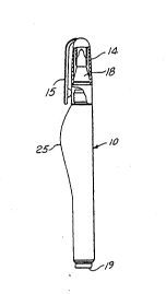
Referring now to the drawing and in particular
to Figures 1, 2 and 3, there is shown a dispenser lo for
depositing liquid material onto a print medium. The
dispenser 10 generally comprises an elongated tubular
body 12 and a cap 14 having a clip 15 suitable for
retaining the dispenser 10 in a pocket of the user. The
tubular body 12 is formed of wall structure providing a
cavity 16 for retaining a correction fluid which may be
any of the types well known in the art, and the fluid is
retained in the cavity 16 by a valve structure 18
disposed at one end of the body and a sealing means 19
i SroS~~ at the opposite end of the body. As best shown
in Figure 3, the valve structure comprises an orifice 20
formed in the forward end of the tubular body and a
plunger 22 extending through the orifice and biased into
engagement with the interior wall structure adjacent the
orifice by virtue of a spring 23 disposed between the
WO9l/18750 PCT/US91/03227
~ 21)637~()
rear of the plunger and wall structure of the body 12.
As best shown in Figure 1, the remaining
element in the dispen-Qr 10 comprises a metallic slug 24
which is disposed within the cavity 16 and effective to
mix the liquid material disposed within the cavity by
~king the disr~n~er causing the slug 24 to produce a
stirring motion within the cavity 16.
In viewing Figures 1 and 2, it should be noted
that the elongated tubular body 12 is of substantially
circular cross-section at either end but has an enlarged
body portion 25 therebetween which is formed of greater
cross-section than either end of the tubular body.
Referring now to Figures 1 and 2 taken in
conjunction with Figures 4 through 7, the sections taken
along the length of the tubular body 12 are
substantially oval in cross-section as they approach the
enlarged portion 25, Figure 7 showing the substantially
circular cross-section which is disposed at either end
of the tubular body 12~
It is evident that the enlarged portion 25
facilitates the squeezing of the material from the
dispenser by providing a portion of the dispenser 10
which is disposed at the dispenser forward end such that
the fingers grip the enlarged portion in a natural and
convenient manner during use of the dispenser, in the
process of covering undesired printed characters.
Referring to Figures 4, 5, 6 and 7, the
sections depicted, while shown to be of equal thickness
for purposes of illustration, are not so but vary in
thickness around the circumference of a section as well
as from one section to another. Typically, that portion
of the tubular body 12 at either end which is depicted
in Figure 7 is of a maximum thickness while the enlarged
portion 25 is of a minimum thickness, the portions on
either end supplying stability and rigidity to the dis-
p~ncer 10 and the enlarged portion providing a section
which is easily squeezed by the user to provide pressure
WO91/18750PCT/US91/03227
" ~ 2063740
-- 7
to the liquid material within the dispenser.
By way of example, the embodiment shown is
manufactured of Nylon 6 material. The tubular body 12
at the rigid section shown in Figure 7 (typical of the
unenlarged tubular body), has a dimension of .025 inch
at A, .029 inch at B, .0295 inch at C, .033 inch at D,
.030 inch at E, and .030 inch at ~. In contrast, the
section shown in Figure 5, taken at the enlarged portion
has a thickness of .0175 inch at A', .016 inch at B',
10.016 inch at C', .012 inch at D', .0185 inch at E', and
.020 inch at F'. The difference in thickness dimensions
between the points B and F or B' and F' as well as the
differences between the points C and E or C' and E' are
not of design but reflect the manufacturing tolerance
and limitations of measuring techniques of the material,
it being understood that the tubular body 12 is
substantially symmetrical about the vertical axis shown,
throughout its length.
- Thus, it can be appreciated that the enlarged
portion 25 is provided with thin walls essentially oval
in cross-sectional shape, which are more flexible and
thereby provide the neCDec~ry flexibility to apply
pressure to the internal cavity 16 by the user, without
sacrificing rigidity of the entire elongated tubular
body 12.
It has been found that a suitable variation in
wall thickness is obtained by manufacturing the
dispenser employing a blow molding process. In the
typical example set forth above, a circular tube of a
moldable material such as Nylon 6, as described, is
provided having uniform wall thickness. The tube is
placed in a mold having a cavity portion for receiving
the circular tube in interfitting engagement and an
enlarged cavity portion extending outwardly from the
wall of the circular tube. By applying pressure to the
internal walls of the circular tube, with the tube in
the plastic flow condition, the walls are expanded into
WO91/18750 PCT/US91/03227
20637~0 - 8 - ~
the enlarged cavity forming a bulbous portion or
enlarged portion 25, which has a wall thickness less
than that of the tube uniform wall thickness, the tube
uniform wall thickness forming the more rigid cross-
section portion of the elongated tubular body 12 as inFigure 7.
Referring now to Figures 3, 8 and 9, the valve
structure 18 is shown to comprise a plurality of
interior wall surfaces of the tubular body 12 which
terminate at the orifice 20. The wall surfaces
generally comprise a cylindrical surface 27 and a
conical surface 26 adjacent the orifice 20, a
cylindrical surface 28 extending rearwardly from the
surface 26 and an interior conical surface 30
terminating at the ~nterior wall 32 of the tubular
body 12.
The plunger 22 is formed of a cylindrical
portion 34 extending outwardly from the orifice 20 and
terminating in a substantially planar surface 35. The
plunger 22 further comprises a conical surface 36
extending rearwardly from the cylindrical portion 34 and
a cylindrical surface 38 extending rearwardly into the
tubular body 12. The main body portion of the plunger
22 is substantially cylindrical in shape and has a step
formed at the rearward end thereof for receiving the
spring 23, and produces an exterior cylindrical surface
40 which is connected to the smaller diameter
cylindrical surface 38 by a conical surface 42. As best
shown in Figure 8, with the plunger 22 biased forwardly
by the spring 23, the conical surface 36 of the plunger
engages the forward portion of the conical surface 26,
closing off the orifice 20 with the cylindrical portion
34 extending beyond the orifice. In this configuration,
the correction fluid contained in the dispenser is
substantially prevented from flowing through the
orifice 20.
As shown in Figure 9, when the planar surface
WO91/18750 PCT/US91/03227
- 20637~0
g
35 contacts a surface of a paper or other material
containing printed matter, the plunger 22 is forced
against the biac of the spring 23 and the cylindrical
portion 34 moves rearwardly into the tubular body 12.
The surfaces 36 and 26 are ~eparated, opening the
orifice 20 to ambient p~ re. As alluded to
previously, it is highly desirable to minimize or
eliminate the problem of high flow rates caused by
naturally occurring internal-external pressure
differences, while at the same time allowing the user to
deposit a desired amount of fluid without excessive
effort. The present valve structure 18 therefore has
been designed such that the valve does not allow
sufficient flow of correction fluid to make an
acceptable correction, without increasing the internal
pressure by sgueezing the enlarged portion 25 of the
~ pen~er 10. In order to accomplish this, the valve
structure 18 i8 provided with a clearance between the
cylindrical surfaces 28 and 38 and between the
cylindrical surface 27 and the outer surface of the
cylindrical portion 34, in combination with a length of
flow path between the surfaces 28 and 38 and the surface
27 and that of the portion 34 which does not permit the
flow of an objectionable, or sufficient amount of fluid
employed in the dispenser when the orifice 20 is open as
shown in Figure 9. That is to say, the designed
restriction between the cylindrical surfaces 28 and 38
and surface 27 and portion 34 is sufficient to require
squeezing of the dispe~-er 10 for fluid flow over the
range of reasonably expected use temperatures and the
resultant change in internal p~-s~lre. By maintaining
the two cros~-sectional areaC, that is the opening
between the surface~ 28 and 38 and the opening between
the surface 27 and the portion 34 as throttling areas,
the design may be changed to accommodate a wide range of
specific gravity of commercial fluids by an increase or
decrease in the designed restriction between the
WO91/18750 PCT/US91/03227
2063-7~0
-- 10 --
cylindrical surfaces 28 and 38 and the surface 27 and
cylindrical portion 34 and/or an increase in the length
of the cylindrical portion~ of the plunger 22 and
corresp~nAin~ portions of the valve wall structure.
In operation, when it ifi desired to correct a
portion of printed matter, the cap 14 is removed from
the dispen~er 10 and the dispenser is located over the
portion on~which the correction is to be made. The
elongated tubular body i~ then prc~ downwardly such
that the planar surface 35 contacts the area to be
corrected, and is forced inwardly opening the orifice 20
at which point the correction fluid does not e~cAp~ from
the orifice but is maintained within the cavity 16 of
the ~i~pen~er 10. The user, by squeezing the enlarged
portion 25 of the elongated tubular body 12, causes an
increase in pressure within the cavity 16 above the
ambient pressure and liquid material flows through the
orifice 20 in a controlled manner.