Note: Descriptions are shown in the official language in which they were submitted.
2a6~l3~
"Article constituted from a plate ~L~luced from a relatively
soft metal and cooking vessel constituting
such an article -
The present invention relates to an article
constituted from a plate produced from a relatively soft
metal .
The subject of the invention i5 also the cooking
vessels constituting this article.
Aluminium is a metal which has numerous advan-
tages. It is light, can easily be deep-drawn or drop-
forged, and conducts heat well. In addition, it is
relatively c~n~ 1. secause of these qualities, it is
universally used in industry, especially for producing
cooking vessels.
However, it does have drawbacks. First of all, it
is relatively soft, 80 that its surface scratche3 easily.
In domestic applications, A1l1m;nil1m is often coated with
a non-stick layer such as polytetrafluoroethylene or with
a layer of enamel. Elowever, the lifetime of these coat-
ings is limited because the ~111mini11m is too soft a
support .
II~Ie~JV~L~ aluminium articles, and in particular
cooking vessels, have a tendency to deform easily due to
the effect of heat generated, for example, by an electri-
cal hotplate or a gas burner.
In order to overcome this dif ficulty, it is
possible either to increase the thic kn~qs of the metal or
to apply a stainlesg steel sheet to the aluminium wall,
for example by hot gtamping. ~owever, in this case, the
_ . . . , _ . _ _ _ _ _ . . .
-
206~136
manufacturlng cost is substantlally lncreased and
the thermal conductlvlty 18 reduced, whlch lncreases the
cooklng t lmes .
Moreover, aluminlum utenslls cannot be heated
lnductlvely, as thls heatlng method requlres the use of
vessels made from magnetlc metal such as ferrltlc stalnless
steel .
The ob~ect of the present lnventlon 18 to modlfy, ln
an economlcal manner, the characterlstlcs of the surface of a
metal ln order to lmprove lts propertles or ln order to render
thls metal capable of belng used ln speclflc appllcatlons.
The artlcle accordlng to the lnventlon, constltuted
from a plate produced from a relatlvely soft flrst metal, 18
characterlsed ln that lt has, on one of lts faces, a metalllc
element ln the form of a perforated sheet or a grld produced
from a second metal or alloy harder than that of the plate,
the metalllc element belng f lxed to the plate by cold stamplng
or drop-forglng ln order to embed lt, at least partlally, ln
thls plate.
More speclflcally, the present lnventlon provldes a
method for produclng a cooklng vessel havlng a bottom and a
slde wall, whlch comprlses the followlng steps ~
a) applylng on a plate produced from a relatlvely
soft flrst metal, a metalllc element ln the form of a
perforated sheet or a grld produced from a second metal or
alloy harder than that of the plate, the metalllc element
havlng a surface substantlally corr~Rr~n~iln~ that of the
bottom of the vessel;
285~1 -ll
B -
20~36
b~ fixing the metalllc element on the plate by drop-
forglng or cold stamplng ln order to embed the metalllc
element, at least partlally, in the plateSand
c) deep-drawlng an assembly constltuted of the plate
and the metallic element fixed to the plate in order to form
the cooking vessel.
~ y drop-for~ing is meant an operatlon which consists
ln striking, for example with a drop hammer, or in pressing
strongly, for example by means of a surface or of a roll, onto
the grld in order to embed it, at least partially, ln the
surface of the metal.
8y grld 18 meant not only a metallic frame composed
of intersecting wires but also a perforated sheet having
circular, square or otherwlse shaped holes.
2854 - 1
~3, 1 1
, 2a~l36
A composite surface is thus obtained having
properties resulting from tho~e of the two metals, that
i~ to say of the base metal and of that forming the grid.
In other words, the properties of the base metal have
5 been modif ied by the grid which is intimately bound to
this base metal.
For example, if the grid is made from a metal
harder than that of the base metal, the presence of the
grid will have the effect of hardening the surface of the
10 base metal.
Moreover, the use of a hard metal grid in as-
sociation with a soft base metal is well suited for the
production of the article according to the invention as,
during the drop-forging, the hard grid, which ha3 a small
15 contact surf ace, penetrates deeply into the sof t base
metal, which ensures an ~Y~ 1 .ont binding between this
grid and the ba3e metal.
Fur~h~ e, if the base metal tends to deform
due to the effect of heat, the presence of the grid (if
20 the latter is made from metal which expand3 le~s on
heating) will render this metal di3tinctly less de-
f ormable .
In another application, if the base metal is not
magnetic (in the case of aluminium, for example), the
25 presence of a magnetic metal grid anchored at the surface
of the metal will render the latter capable of being
heated inductively.
In all cases, the provision of a grid-shaped
second metal, on a given base metal, does not greatly
-- 4 --
_ _ _ ... . . . .. . , . .. _ _ . .
~ 2~6~13~
affect the cost and enables the properties of the base
metal to remain intact.
- According to another version of the inventiOn,
the article has, on each o~ its two f aces, a metallic
5 element corresponding to the ab-,v~ Lioned definition.
According to a different version of the inven-
tion, the article is such that the surface of the element
or elements, which surface is on the opposite side from
the plate, is covered by a coating made from metal
10 identical to the first metal.
According to yet another different version of the
invention, each surface of the plate to which an element
is f ixed is covered by a continuous enamel or f luoro-
carbon-resin layer.
According to a further version of the invention,
the article comprises at least two metallic plates fixed
one against the other and provided at their interf ace
with a metallic element which is partly embedded in the
metal of one of the plates and in the metal of the other
20 plate.
The invention thus enables the Alllm;nillm bottoms
of cooking vesselg to be reinforced, the lifetime of
their non-stick coating to be increased and enables them
to be rendered capable of being heated inductively, if
25 the added grid is made from magnetic metal, such as
ferritic stainless steel.
Other particular featureg and advantages of the
invention will further emerge from the description
hereinbelow .
-- 5 --
.. . . ... _ . ..
- ~ 2~641 36
In the attached drawings, given by way of non-
limiting examples,
- Figure 1 is a perspective view of a metallic
disc to which is applied a grid of a metal different from
5 that of the disc,
- Figure 2 is a sectional view showing diagram-
matically the process for drop-forging the grill on the
disc,
- Figure 3 is a view on a larger scale of the
10 detail A of Figure 2,
- Figure 4 is a view similar to Figure 3, showing
the grid ~ d in the metal of the disc, after drop-
f orging,
- Figure 5 is a partial plan view, on a larger
15 scale, showing the grid fixed on the surface of the
metal,
- Figure 6 is a sectional view in the plane VI-
VI of Figure 5,
- Figure 7 is a sectional view of a plate com-
20 prising, on its two faces, a perforated sheet; ~ d inthe metal of the plate,
- Figure 8 is a sectional view of the wall of an
article in which the surface of the said sheet or grid,
which surface is on the opposite side from the plate, is
25 covered by a coating made from metal identical to the
said f irst metal,
- Figure 9 is a view similar to Figure 8 of a
variant G ' 'ir--nt of the invention according to the said
Figure 8,
-- 6 --
_
2~6~13~
- Figure 10 is a sectional view showing two
plates and three perforated sheets before their assembly
by drop-f orging,
- Figure 11 is a sectional view of the composite
5 plate thus obtained after drop-forging,
- Figure 12 is a partial plan view of a per-
f orated sheet,
- Figure 13 i3 a partial aectional view of a
plate carrying a perf orated sheet partially ~ d in
10 this plate,
- Figure 14 is a sectional view of a composite
plate in which two perforated sheets are:
- Figure 15 is a partial plan view of a metallic
element in the form of an -Yr_n~ d sheet,
- Figure 16 is a sectional view of a cooking
vessel carrying a grid on the outer face of its bottom,
- Figure 17 is a view on a larger scale of the
detail B of Figure 16,
- Figure 18 is a sectional view of a coolcing
20 vessel carrying a grid on the inner face of its bottom,
- Figure lg is a view on a larger scale of the
detail C of Figure 18.
The article constituted from a plate produced
from a relatively soft first metal is characterised in
25 that there i8 applied ( see Figures 1 and 2 ) to the
surface 1 of the said metal, in the form of a disc, a
grid 2 of another metal, and in that this grid 2 is f ixed
to the said surface 1 by drop-forging in order to embed
it, at least partially, in this surface.
-- 7 --
206~136
.~
The grid 2 is preferably made from a harder metal
than that of the 3aid surf ace 1.
Figure 3 shows, on a large scale, the initial
stage of applying the grid 2 to the disc 1.
Due to the effect of the force applied by the
hammer 3 ( see Figure 2 ) on the grid 2, the latter i8
driven into the metal of the disc 1, as indicated in
Figure 4.
The depth of penetration depends on the f orce
applying the grid 2 to the disc 1, on the relative
hardnesses of the metals of the grid 2 and of the disc 1
and on the diameter of the wire with which the grid 2 has
been produced.
In the case of Figure 4, the grid 2 is driven
into the metal of the di~c 1 over a depth which cor-
respond~ liubstantially to half the diameter of the wire
of the grid 2.
Employing a greater drop-forging force, it is
pos~ible to embed the grid 2 entirely in the disc 1, as
indicated in Figure 6.
The preferred metal of the relatively soft metal
disc 1 is ~ m; ni llm.
However, the metal may al~3o be copper, tin, lead
or an alloy of one or more of these metals, or any other
metal or alloy.
The grid 2 may be made from ferrous metal or
steel having magnetic properties.
In this case, not only does the grid 2 ~
in the surf ace of the disc 1 reinf orce and harden the
-- 8 --
2~6413~
.
latter, but it furthermore render3 the latter capable of
being heated inductively.
This grid 2 may thus be made from stainless
steel .
In the case of an aluminium disc 1 and a stain-
less steel grid 2 composed of wire of diameter lying
between several tenths of a mm and one mm, the force
employed during the drop-forging must be at least equal
to approximately 10 tonnes per cm2.
The grid 2 may have any kind of meshes, square,
rectangular, hexagonal or other shapes.
Instead of being produced by wires, the grid 2
may be constituted by a cut-out metal sheet or in th~
form of PYr~nr~ metal.
In the ~ of Figure 7, the metallic plate
l compri3es, on its two faces, a metallic element 2 in
the f orm of a sheet provided with openings 4 . These two
elements 2 are completely ~ by drop-forging in the
metal of the plate 1. Indeed, the metal of the plate 1
completely fills the openings 4 of the sheets 2.
Of course, the ~hil knf-ss of the sheets 2 is small
in relation to that of the plate 1. The drop-forging
operation involves the application on the sheet 2-plate
1-sheet 2 sandwich a pressure sufficient for the two
sheets 2 to be able to penetrate into the metal o the
plate 1 and for the metal of the latter to be able to
f low into the openings 4 of the sheets .
The two metallic elements or sheets 2 may be
produced in identical metals or alloyg. The plate 1 may,
_ g _
.. .... _ . .. .. _ ... .. . _ _ _ _ _ _ _ . _ .
~ 2û6~13~
for example, be made from a soft metal such as aluminium
or copper and the sheets made from harder metal such as
steel .
In this case, a compo3ite plate is obtained
5 having two faces which are hard and resistant to abrasion
and ~-hJqni~!~l shock. In addition, the composite plate
has a distinctly improved resistance to deformation due
to mechanical or thermal stresses, whilst keeping the
essential properties of aluminium ( lightness and good
10 thermal conductivity) or of copper (good thermal conduc-
tivity ) .
Yowever, the two metallic elements or sheets 2
may be produced in different metals or alloys.
In this case the composite plate will have faces
15 having different -h~n;~l or thermal properties, which
may be advantageous in certain applications. In this case
too, the composite plate will keep, for the most part,
the advantages provided by the base metal of the plate.
In the ' o~li t of Figure 8, there is shown, in
20 partial cross-section, the wall of an article such as a
cooking vessel comprising a plate 1 produced from a first
metal to which is fixed, by cold stamping or drop-forg-
ing, an open-work sheet 2 or grid produced from a second
metal different from the first metal.
In accordance with the present invention, the
surface of the said open-work sheet 2, which surface is
on the opposite side from the plate 1 is covered by a
coating 5 made from metal identical to the said first
metal .
- 10 -
~ 2~13~
Thus, in the case of a cooking vessel, the plate
1 is made from aluminium and the open-work sheet 2 is
made f rom steel sheeting covered with an aluminium layer
5. As a result, the surace of the plate 1, to which the
said open-work sheet 2 is fixed, and that of this sheet
2 may be covered by a continuous enamel layer 6 as
indicated in Figure 8.
In the example of Figure 8, the surface of the
plate 1 and the surf ace of the open-work sheet 2, which
are covered by the enamel layer 6, are located in
alignment with each sther.
Thu~, the enamel layer 6 totally masks the open-
work steel sheet 2. sy virtue of the aluminium layer 5
which covers the surf ace of the sheet 2, the enamel 6
adheres both to this sheet and to the aluminium of the
plate 1.
Moreover, this enamel layer 6 protects the steel
sheet especially as regards to rusting, and makes it
easier for the surface of the Alllm;n;llm to be cleaned.
The open-work steel sheet 2 may be adjacent to
the outer or inner surface of the bottom of a cooking
vessel .
By virtue of the presence of this open-work sheet
made from steel or other ferroug metal, the cooking
vessel may be used on an induction plate, whilst having
all the advantages specific to Alllm;n;llm vessels.
In the case of the example shown in Figure 9, the
surface of the steel open-work sheet 2 projects relative
~o ~e sur~ace a o~ t e A~ lm;nillm plate 1.
~ 206~1 36
In this case, the enamel coating 6 has, in line
with the projecting portions of the open-work sheet 2,
raised features separated by hollows.
The raised f eatures of the enamel layer 6a enable
5 the wear of the enamel layer to be localised in discrete
zones such that the hollow portions of the enamel
preserve their original shine.
The enamel layer 6 may of course be replaced by
a layer of fluorocarbon resin such as polytetrafluoro-
10 ethylene (PTFE).
The at~ 1, of the PTFE to the z~ m; n; ll~ isproduced by virtue of a prior acid etch which has the
effect of creating attachment cavities on the aluminium
sur~ace .
Because the open-work sheet 2 is covered with an
aluminium layer, these attachment cavities are also
created on the open-work sheet 2, which enables the PTFE
coating to adhere both to the aluminium of the plate l
and to the open-work sheet 2.
In the case of the ~ L according to
Figures 10 and ll, the composite plate 30 comprises two
metallic plates 7, 8 f ixed one against the other and
provided at their interface with a metallic element or
sheet 9 having openings lO which is partly ~ <1 in
the metal of one 7 of the plates and in the metal of the
other plate 8.
The two metallic plates 7, 8 may be produced in
identical or different metals or alloys.
The f lowing of the metal of the two plates 7, 8
-- 12 --
2~6413~
into the opening3 10 of the metallic sheet 9 enables an
excellent binding between the two plates 7, 8 to be
obtained .
In the example of Figures 10 and 11, the two
5 metallic plate3 7, 8 carry, on their outer face, a
metallic element 11, 12 corrpqpon~i;ng to the above-
mentioned def inition .
In thi~ example, the composite plate 30 produced
from two plate~ 7, 8, for example made from ~ min;l1m~ i8
reinforced by three layers 9, 11, 12 of a metal having a
greater hardness and - -hAni e Al gtrength than Alllm;n;llm,
which thus enable the - ~hAni ~ Al propertieg of the plate
to be considerably PnhAnf Pd.
In addition, the presence of the perforated
sheets 9, 11, 12 has, because of their smaller ~hi~kne~s,
very little effect on the density which thus remain~
close to that o~ aluminium.
Of course, the perf orated sheet 9 may be o~ a
different type from that of the other two sheets 11, 12,
20 tler-nrlin~ on the desired properties.
In the ~ ; t of Figure 14, the composite
plate 13 comprises three metallic plates 14, 15, 16 fixed
one against the other and proYided at each of their
interfaces with a metallic element or sheet 17, 18
25 colLc-~ullding to the abu~c tioned definition.
In this: -~; t, the perforated metallic
sheets 17, 18 have the following two functions:
- f ir~t of all they enable the binding between
the pla~e 15 ~nd the plateg 14, 16 to be ensured b~
~ 2~13~
virtue of the f lowing of metal of the plates into the
openings of the sheets 17, 18;
- moreover, these sheets 17, 18 enable the com-
posite plate 13 to be reinforced or strengthened in order
5 to give the latter better resistance to -hAniA1
stresses .
The three plates 14, 15, 16 may be produced from
the same metal, such as Alllminillm. ~owever, they may be
made from different metals, ~lPp~nrlin~ on the anticipated
10 applications. Thus, the two outer plates 14, 16 could be
made from copper and the inner plate 15 made from
Alllm;ni~lm.
Thus, the inner plate 15 i~; jacketed externally
by two copper layerg enabling the thermal conductivity to
15 be improved.
Figure 15 ghowg a sheet 19 made from ~lrrAnrl~A
metal which may replace the perforated sheets described
hereinabove .
Of cour~e, the composite plates that have just
20 been described may be u~ed directly in various industrial
applications or serve as a basis for the production, by
deep-drawinq, of various articles and, in particular, of
cooking ves3el~ whose bottoms have greater resistance to
abrasion or to deformation8 due to thermal or ---h Ini;~
25 stresses.
Figure 16 shows a cooking vessel, such as a
frying pan, ~allr~.pAn or cake mould produced from an
aluminium sheet of ~hi~ knF.~s lying between 1 and 3 mm.
On the outer face of the bottom 21 of the vessel
-- 14 --
. .. . .. . . _ _ _ _ _ _ _ _ _ . _ _ . . .
2~ 36
20 has been: ' - 'APd, by drop-forging, a ferritic stain-
less steel grid 2 which i5 driven right into the metal,
as indicated in Figure 17.
The grid 2 -~ sd in the bottom of the ve3sel
5 20 confers on the latter the following te~-hni~ A1 ad-
vantages:
a~ hardening of the bottom of the vessel, which
enables the latter to resist wear better,
b) i ~ u~ L to the resistance of the bottom to
10 deformations generated by temperature variations; because
of this, the bottom remains plane and the heat transfer
with a hotplate remains optimal,
c) the vessel may be heated inductively, by
virtue of the presence of the magnetic stainless 3teel,
d) because the aluminium i5 an PY~F.l 1 Pnt heat
conductor, the heat stored by the stainless steel of the
grid is transferred quickly and uniformly across the
A 1 llm i n i um bottom 21,
e) because the stainless steel grid is discon-
20 tinuous, it i5 po~ihl~ to adjust the heat transfer
across the bottom of the vessel to a reduced value and,
consequently, to avoid abrupt and excessive heating of
the food,
f) the presence of the grid only slightly affects
25 the manufacturing cost and in no way impedes the deep-
drawing of the aluminium vessels.
As a consequence, the abovementioned cooking
vessel has all the advantages due to the use of aluminium
whilst also having the advantages provided by the stain-
-- 15 --
_ _ _ _ _ .. . . . _ _ .. _, . _ _ _ _ _ _ _ _ _ _ _
~ 206~3~
less steel grid.
If the possibility of inductively heating is not
desired, the grid may be made from ordinary steel or any
other metal harder than ~ mi n i llm .
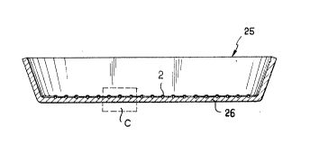
In Figure 18 is shown another aluminium cooking
vessel 25, the bottom 26 of which has, on its inner face,
a grid 2, for examele made from stainless steel or
another relatively hard steel.
It is seen from Figure l9 that this grid 2 is
only partially ' - '-'ed in the metal of the bottom 26 80
that it projects from the inner surface of this bottom
26 .
In this example, a non-stick coating 27, for
example made from polytetrafluoroethylene, covers the
inner surf ace of the bottom 2 6 and the grid 2 . Because
the latter projects in relation to the surface, the
coating 27 forms a raised feature in line with the wires
of the grid.
The t~hn;cAl advantages provided by this embodi-
2 0 ment are the f ollowing:
The presence of the grid 2 projecting from the
surface of the bottom 26 of the vessel hardens this
surface which enables the non-stick coating better to
resist the action of sharp implements.
In fact, the sharp implement does not reach the
soft ~ minillm surface, as the stainless steel grid
projects from the latter. As a consequence, the sharp
L only affects the projecting portions of the
grid, 80 that only the portion of the coating which
-- 16 --
. . _ . . . ~
~ 2~413~
covers the grid suffers some damage. This damage however
will remain virtually invisible since it will be
loc ~ 1 in very small zones.
Moreover, the fact that, by virtue of the grid 2,
5 the non-stick coating forms a uniformly raised feature on
the inner surface of the vessel, enables the contact
surface of the food with the surface of the vessel to be
limited, which limits even further the attachment of this
food to this surface.
In order for the abovementioned advantages to be
fully realised, there is advantage in the distance
between two ~ hho~lring wire8 of the grid not ~ e~A;n~
several mm.
The invention is applicable to fields other than
15 the manufacture of cooking utensils. In fact it may be
applied to any te~hnir~l field where it is desired to
modify the properties of the 3urface of any metal by
' ~ li nlJ in the latter a grid made from another metal.
This grid may be constituted by welded or woven
20 wires in such a manner as to form meshes of any shape.
Moreover, the wires of the grid instead of being of
circular crogs-section may be of square or other cross-
section .
Likewise, in the embodiments shown, the grid
25 composed of circular cross-section wires may be replaced
by a sheet, for example made from aluminium perforated
with circular holeg, for example of diameter equal to
0.75 mm separated by approximately 1.5 mm.
Of course, the invention is not limited to the
-- 17 --
_ _ _ _ _ . , . , ,, . ..... . _ .. ,, . . .. , .. , ,, . , _ _
~, 2~4~ 3~
~y l~ry ~iir nt8 which have jugt been degcribed and
it is possible to bring to the latter numerous modifica-
tions without straying from the scope of the invention.
In particular, the various ~ nts of the
5 articles which have just been described may form the
subject of multiple combinations between them or with
other processes appearing in the prior art 80 as to
further improve the characteristics of the articles and
especially of the cooking vessels thus obtained, without
10 straying from the field of the invention.
It will be possible, inter alia, to use metallic
elements, sheets or grids, of very varied 3hapes, and to
embed by cold or hot stamping or by rolling one of the
said elements on the surf ace of one of these plates or
15 between at least two metallic plate~ 80 that it con-
stitutes their interface(s). By interpoging metallic
elements between the plates, composite plates are thus
i~ormed comprising a variable number of layers.
On at least one of the faces of a single or
20 composite plate, it is possible to embed a grid or a
sheet provided, or not, on its outer face with a coating
made from metal identical to the metal constituting the
surface of the said plate, and then optionally applying
to this face an enamel or fluorocarbon-resin coating.
-- 18 --