Note: Descriptions are shown in the official language in which they were submitted.
206~152
rTMTT~n sr~cK RAIr~cA~ CON~CTOR
BAcKGRou~n OF T~ INV~TION
This invention relates to an improved railcar connector
assembly and more particularly to a freight railcar drawbar
assembly and an elastic spacer therefore.
Railcar connections are made of steel and must be able to
withstand large buff (retarding) and draft (pulling) loads yet
be able to angle horizontally and vertically and to twist at
the car sill interconnection so as to permit adjacent cars to
negotiate turns and inclines and to rock transversely. In
some special applications, such as coal carrying railcars, the
connectors between sucessive cars must permit rotation of a
car about its longitudinal axis for dumping its load.
Furthermore, upon buff and draft impacts, the connections
should essentially absorb movement due to longitudinal slack
(the spacing between parts), such as by a cushioning draft
gear, or be substantially slack free. In freight rail car
connectors a popular slack free arrangement incorporates a
wedge that is gradually inserted between connector and car
sill parts to compensate for initial spacing and for wear that
occurs during operation. Usually the wedge is located between
a follower block and a sill pocket wall. Examples of slack
free wedge type connections are described in U.S. Patents Nos.
3,716,146; 4,258,628; 4,456,133 and 4,549,666.
gl~2
A problem with some railcar connections is that the
connector parts are maintained so tight as to bind and hinder
angling and twisting of the connector even when under draft
loading especially in a new condition. This is particularly
troublesome between adjacent parts that are manufactured with
multiple or complex curves on bearing surfaces or where the
centers of curvature of the bearing surfaces do not precisely
coincide. Drawbar connectors present such problems; and slack
free connectors employing wedges are particularly subject to
this problem when the connector under goes maximum draft
loading and the wedge efficiently moves between parts. Rotary
connectors employing gravity fed wedges also present a problem
that the wedge may become withdrawn or cocked when it is
temporarily inverted.
Therefore, it would be advantageous to allow limited
slack to occur between connector parts generally, and
particularly with respect to wedged connectors where limited
slack occurs without compensatory movement of the wedge. A
prior attempt to accomplish this in a wedged slack free
connector is described in U.S. Patent No. 4,258,628 wherein
two vertical elastomer strips are seated in vertical grooves
at each side of a wedge contacting face of a follower block in
an articulated rail car connection. However, the amount of
elastomer that may be utilized in such an arrangement is
relatively small resulting in low resistance and chase to
wedge movement; and the dual arrangement of resilient strips
20641 52
may cause undesirable angling of the wedge under certain
conditions when the connector is angled horizontally under
draft load. Moreover, this arrangement, upon failure of
. .
either ~ne of the elastomer strips, may require replacement of
a follower block that has become beneficially honed to the
shape of a connector butt end through usage.
Cushioning draft gear may ameliorate the problems in some
connectors, such as couplers where commonly used. However,
draft gear is relatively expensive and heavy; and,
accordingly, it would be advantageous to provide for limited
slack and eliminate the draft gear.
~U~MA~Y OF T~ INV~TTON
Accordingly, it is a principal object of the present invention to
provide an improved limited slack railcar connector assembly having a
single centrally disposed resilient member, so as to permit limited
slack sufficient to facilitate angling of the connection.
Basically, the present invention includes a single resilient pad
of an elastomeric material held within a larger congruent opening of a
spacer cage that is insertable between two abutting parts of a
connection assembly - such as between the follower block and wedge - ,
and functions to maintain a limited amount of slack in the assembly by
resiliently applying a degree of compression between the assembly
parts during draft loading on the connector.
d
~ 2064 1 52
Preferably, the pad has a center which is substantially aligned
with the longitll~; n~l axis of the assembly and, more preferably, the
centers of the pad and follower block are aligned. The cage may be in
the form of ~ rectangular metal plate with a through-opening centered
in the plate and the elastic pad may be a circular disk held within
the through- opening.
- RRT~ D~-~CRIPTTON OF T~ DRAWIN~.~
Further objects and advantages of the present invention
will become apparent upon reading the following detailed
description in conjunction with the drawings wherein:
FIGURE 1 is a plan view in partial section of a preferred
drawbar embodiment of the present inventions;
FIGURE 2 is a side elevation view in partial section of
the embodiment of FIGURE l;
FIGURE 3 is a partial section view taken at line 3-3 in
FIGURE 2.
FIGURE 4 is a detailed sectional side elevation view of a --
spacer cage and resilient pad removed from the embodiment of
FI~URES 1-3; and
FIGURE 5 is an end view of the part shown in FIGURE 4.
B~
2064 1 52
D~TAIr~ D~SCRTPTION OF A pREF~ n ~MRODIMF~T
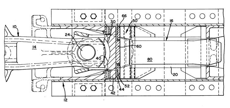
Railcar connector assemblies usu'ally comprise a male
connector member generally 10 that is received in, and
pro~ects~'outwardly from, a car sill generally 12. While there
are several forms of connectors to which the present invention
pertains, such as articulated connectors, couplers (including
E and ~ types) and drawbars (including rotary drawbars) to
which the invention may be applied, the illustrated preferred
embodiment of the present invention is in the form'of a
drawbar 14 that is received in a sill pocket formed by'a yoke
generally 16 having a sloped forward end wall 18 buttressed by
an incompressible filler 20 (such as a steel tube). The
drawbar 14 is of standard construction, pivotable both
horizontally and vertically on a vertical pin 24 held at the
forward end of the yoke 16, and having a curved butt end 30
that is received against a similarly curved bearing surface 40
of a follower block 42. The follower block 42 has a flat rear
face 44 spaced from the end wall 18 by a gravity wedge
generally 50 and a resilient means of the present inve~tion.
In prior wedged drawbar assemblies the wedge is in direct
abutting relation to both the follower block and the end wall.
Similarly in prior coupler construction a follower block may
abutt a pocket end wall or draft gear. However, according to
the~present invention a resilient means comprising an elastic _
pad 60 having flat parallel faces 62 of a selected surface
area "A" is positioned between the rear face 44 of the bearing
-
20641 52
block 42 and the next adjacent connector part such as the
forward face 52 of wedge 50 illustrated in the FIGURES. It is
important that the center of the elastic pad 60 be
approximately centered on the longitudinal axis of the
connector assembly, that is the pad 60 is essentially aligned
with the generation points of the curves of the follower block
bearing surface 40 and the butt end 30 of the drawbar 14. In
that way, the elastic pad 60 will uniformly cushion the
bearing block 42 and next adjacent part such as forward face
52 of wedge 50 during virtually all angles of the drawbar 14.
The pad 60 is confined to the aforementioned aligned
position by a spacer cage 66 which is in the form of an
incompressible plate 68, preferably of steel having an opening
70 congruent with (e.g.. the same shape) but larger than the
dimension of the pad 60 which is held therein by a plurality
of studs 72 secured to the plate 68 and projecting into the
opening 70. It will be understood that the cage 66 must be of
a shape and dimensions to conform with the connector assembly
and fit within the aforedescribed sill pocket. In the
embodiment illustrated, the sill pocket is defined by the yoke
16 which has horizontal straps 80, 82 that extend across the
forward end wall 18 to beyond the pin 24. Accordingly, as
shown in FIGURE 3, the wedge 50 has upper and lower notches
90, 92 to accommodate the respective yoke straps 80, 82; and
the plate 68 of spacer cage 66 corresponds in size and shape
to the follower block 42 and fits between the yoke straps 80,
i ` 206~1~2
82. Also in the preferred embodiment the pad 60 is a circular
disk and opening 70 is circular and concentric; however it
will be understood that other congruent shapes, such as
square, diamond and star, may be functional.
It will also be noted that the thickness of the pad 60
slightly exceeds the thickness of the plate 68 by a dimension
"S". The difference in thickness "S" is the amount of limited
slack designed into the illustrated portion of the connector
assembly, that is in one male to female connection.
Preferably, one pad face 62 is coplanar with a surface of
plate 68. Also it is preferred that the volume of space
provided between the peripheral edge of the pad 60 and the
congruent wall of the plate opening 70 will equal or slightly
exceed the proportionate volume of the pad 60 represented by
the difference in thickness "S" multiplied by the area of its
face 62 (S X A). Otherwise stated the volume of the opening
70 is at least equal to the volume of the pad 60. In that way
when the connector assembly is fully compressed under buff
loading the maximum volume displacement of the elastic pad 60
will be fully contained within the plate opening 70 and the
elastomer will not become overstressed and permanently
deformed. Thus when the loading on the connector assembly
cycles from buff to draft the pad 60 will resume its original
shape and thickness and thereby constantly exert pressure
against the wedge 50, preventing further wedge insertion,
until wear induced spacing exceeds the dimension "S". Yet at
20641~2
all times under draft load conditions, the elastic pad 60 will
permit limited rearward movement of the follower block 42
caused by angling of the drawbar 14.
For rotary wedged connectors it will be understood that
the aforementioned elastic pad 60 will constantly exert
sufficient pressure between the connector parts to maintain
their relative positions when inverted and when the connector
butt rotates against a follower block.
The foregoing details have been provided to describe a
best mode of the invention and further variations and
modifications may be made without departing from the spirit
and scope of the invention which is defined in the following
claims.