Note: Descriptions are shown in the official language in which they were submitted.
WO 91/03216 1 2 0 ~ ~ 2 3~CT/EPgo/01428
Hyperex~ension orthesis with movable sternal pad
The invention relates to an improved hyper-
exten~ion orthe6is, especially vne in which the distance
of the sternal pad from the base plate adapts auto-
S matically to different body postures during wearing.
In all known three-point support cor~ets after
B~hler, ~o-called hyperextension ortheses, the pads are
rigidly arranged. ~he distance of the pads from the base
plate i~ adju~ted by shortening the chest and abdominal
rods upon adaptation by the orthopedic specialist. In
the case of elderly patients there are difficultie~,
caused by incorrect posture and when sitting, to the
extent that the sternal pad is pushed upwards as a result
of the altered body posture and presses on the windpipe
and leave behind chafe marks.
The report by the company Otto Bock: ~Hyperexten-
sionsorthese in Modulbauweise~ [Hyperex~ension orthesis
in modular design] in Medizinisch-Orthop~dische Technik,
Volume 5, 1987 and US-RE 31,564 disclose hyperextension
ortheses of the generic type which, with the aid of
oblong holes, permit a simple adaptation of the position
of sternal pad and symphysis pad to the body size of the
patient. However, only one single adaptation is possible
in thi3 way. The real problem of a dynamic adaptation of
the position of the sternal pad to the respective body
posture of the patient i~ consequently not solved.
The aim of the present invention i8 therefore to
pro~ide a constructional design of a hyperextension
orthesis which overcome~ these disadvantages and which
also en~ures the correct positioning of the sternal pad
in the event of a varying body posture of the wearer.
This aim is achieved by means of a hyperextension
orthe6is with a base plate, an abdominal rod extending
downwsrds therefrom with a symphysi~ pad, branche~
extending to both sides with locking elemen~s, and an
upwardly extending chest rod at whose end an oblong hole
REPLACENENT PAGE
20~237
WO 91/03216 - 2 - PCT/EP90/01428
is provided for engagement of a screw for ~ecuring a
~ternal pad. The characterizing feature of the
construction according to the invention consi~ts in the
fact that the sternal pad has a groove for receiving the
che~t rod, and an elongate tongue extending out from the
lower end of the pad for movable engagement in a slide
sleeve formed in [~ic] on the chest rod at a distance
from the oblong hole.
The screw for securing the sternal pad is chosen
in such a way that the screw head bears securely only on
the che~ rod, so that a sliding in the oblong hole is
readily possible.
The groove for receiving the chest rod is pre-
ferably formed on the side of the ternal pad directed
away from the body, and the ~lide sleeve is preferably
arranged on the side of the chest rod directed toward the
body. Upon initial ad~ustment of the hyperextension
orthesi~, the length of the chest rod i~ chosen such that
the hyperextension orthesis bear~ upon the correct body
site. If the distance between the ~ternal pad and the
base plate is now shortened as a re~ult of a change of
body po~ture, the tongue or the slide pushes deeper into
the slide sleeve of the chest rod, as a result of the
secure positioning of the sternal pad on the body, 80
that the upward pushing of the ~ternal pad and the
pressure on the windpipe do not occur. If the body
po~ture lead~ to an increased distance between the
sternal pad and the base plate, the slide slips slightly
further out of the slide sleeve. This constructional
design of a movable slide adapts the distance between
sternal pad and base plate automatically to the body
posture, the pressure of the sternal pad upon the body
remaining ba~ically constant. The relief of the
vertebral bodies of the lumbar spine and thoracic spine
achieved by the corset is likewise maintained constant.
The slide sleeve can be made of plastic or metal.
Suitable plastic~ are thermo plastic~ with good surface
REPLA OEME~T PAGE
206~237
WO 91tO3216 - 3 - PCT~EP90/01428
propertie~, such as polyamide, polyolefins, poly-
urethanes, polycarbonate. Homopolymers are suitable as
well as copolymers.
The slide sleeve preferably has a U-shaped
cro~s-section, so that between the chest rod and the
slide sleeve there is a space for receiving the tongue.
If the ~lide sleeve is made of plastic, it can be
connected to the che~t rod by means of gluing, riveting
or screwing. If the slide sleeve is made of metal, it
can be connected to the chest rod by means of gluing,
riveting, soldering or welding. The slide sleeve can
also be worked out from the material of the chest rod
itself, if the material is chosen appropriately thick.
In order to produce a slidable connection between the
tongue and the chest rod, in another embodiment, in order
to form a ~lide sleeve, the chest rod iq bent round to
such an extent that the bent edges cover over the tongue
9 at least partially. In such an embodiment it i8
preferable for the gap which msy remain between the bent
edges of the chest rod to be covered with a pla~tic film.
If the tonguo and the chest rod are made of met:al, it is
preferable for the surface of the slide sleeve and/or the
tongue and the che~t rod to be provided with a plastic
layer with good ~urface slip. A plastic which is par-
ticularly preferred for this purpose is polytetrafluoro-
ethylene. However, other plastics can also be u~ed for
the surface coating.
The chest rod i9 normally made of metal. It i8
also po~sible, in principle, to form the chest rod from
fiber-reinforced pl~tic. In this case it is advan-
tageous, for reason~ of production technology, to form
the slide sleeve simultaneou~ly, for example by in~ection
molding.
The in~ention i8 illu~trated in greater detail
with reference to the figures.
ure 1 shows the front part of a hyperextension
ortheYi~ in a diagrammatic repr2sentation. ~eference
REPLAC~M~T PA OE
2~237
WO 91/03216 - 4 - PCT/EP90/01428
number 2 designates the ba~e pla~e, from which there
downwardly extends the abdominal rod 6 at whose end the
symphysis pad 3 is secured. Extending upward3 from the
base plate 2 i5 the chest rod 5~ with the sternal pad 4
arranged at its end. Extending to each side from the
ba~e plate 2 are branches at whose respective ends
locking elements 7 are provided for connection to the
back part (not shown).
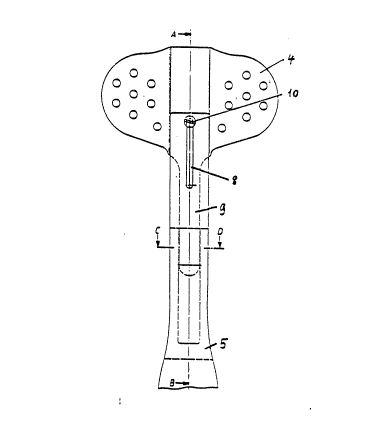
Fioure 2 shows the design according to the
invention of the che~t rod 5 and of the sternal pad 4.
On the surface of the sternal pad 4 directed away from
the body there is a groove for receiving the chest rod 5.
The che~t rod has at its end an oblong hole 8 extending
in the longitudinal direction. The oval sternal pad 4
has at its lower end an elongate tongue as a slide for
engagement in the slide sleeve 11, which is guided
between the sleeve and the che~t rod 5.
The connection of the sternal pad 4 to the chest
rod 5 is effected by the screw 10 which is screwed into
the pad through the oblong hole 8 in the chest rod 5.
The screw head can slide in the oblong hole 8 on the
chest rod 5, at the same time as which the depth of
insertion of the tongue 9 into the slide sleeve 11 in the
chest rod alters.
Fioure 3 is a ~ection along the line A-B in
Figure 2 and shows the design of the guide for the tongue
9, which is designed as slide sleeve 11. The sternal pad
4 with the slide 9 is connected in a slidable manner to
the chest rod 5 by means of this constructional design.
The slide 9 pu~he~ into the gap between the slide sleeve
11 ~nd the che~t rod 5 and i~ secured again3t complete
pulling out from the screw 10, wh1ch can ~lide in the
oblong hole 8 of the chest rod. It i~ preferable to
provide the ~ide of the sternal pad 4 directed away from
the body with a padding 12. It has proven particularly
advantageous to design the padding 1~ with a wedge-shaped
cros~-3ection, i.e. thicker at the upper end of the pad
REPLACEMEN~ PAGE
20~37
Wo 91/03216 - 5 - PCT/~P90/01428
4 than at the lower end.
Fiqure 4 is a section along the line C-D in
Fisure 2 and shows an embodLmen~ of the slide sleeve il
on the chest rod 5, with the slide 9 guided therein. A
U-6haped part 11 is arranged on the side of the chest rod
5 directed toward the body in such a way that the slide
9 can be pushed into the ~lot between the ch0st rod and
the leg~ of the U-profile. However, it is also pos ible,
in principle, for the edges of the chest rod 5 to be bent
round to such an extent that they engage over the slider
in order to form a slide guide. In such an embodiment
it i9 advantageous to covex the guide completely with a
protective layer in order to prevent the catching of
foreign bodies in the guide rail. The chest rod S and
slide 9 are made of stable material, preferably of metal.
However, it i~ also pos~ible, in principle, to produce
the sternal pad with a slide made of fiber-reinforced
plastic. In order to obtain a permanent, low-noise
sliding, it i8 advantageous to cover the slide 9 or tha
surface of the chest rod 10 [sic] and the slide sleeve 11
with a plastic with good surface slip. It i9 par-
ticularly advantageous to produce the U-shaped part 11
itself from a plastic with good surface slip.
The secure connection of the slide sleeve 11 to
the chest rod 5 can be achieved, for example, by gluing,
riveting, screwing or soldering.
However, it is also possible, in principle, to
arrange the guide for the slide 9 on the side of the
chast rod 5 directed away from the body. Howev0r, this
design is not preferred since the slide sleeve 11 must
then be made more stable in order to guarantee the
necessary ~upport guiding of the che~t rod 5 for the
sternal pad 4.
REPLACEMENT PAGE