Note: Descriptions are shown in the official language in which they were submitted.
2~6~
SEL~-RIGHTING TOY CAROUSEk
The present invention relates to
self-righting toys, more particularly to a
self-righting toy having an independently
rotatable, eccentrically mounted weight, which
rotates to its lowest available position upon
displacement of the toy from an upright position.
Backqround of the Invention:
Prior self-righting toys include U.S. Patent
No. 2,554,516, wherein a self~righting toy
includes an inner display figure which oscillates
upon a spring.
U.S. Patent No. 4,522,604 discloses a
rockable toy with a reflecting mirror, wherein the
body of the toy oscillates about a stable position
in which the center of gravity is situated above
the poin-t of contact of the toy and a support
surface.
U.S. Patent No. 4,355,4~1 discloses a
mechanical carousel top having a base stand on
which a -turn table is rotatably mounted. The turn
table is rotated relative to -the base by a drive
assembly including a driver and a unidirectional
clutch assembly actuated by a reciprocating
plunger.
Summary of the Invention:
The toy of the present invention includes a
self-righting carousel having an independently
rotatable eccentric weight.
The toy includes a base having a convex
external surface for contacting a support surface
and a weighted bottom to provide a self-righting
force. A platform having a central aperture is
attached to the base. A support shaft extends
upwardly from the inner surface of the base
--1--
2~326
. throuyh the aperture in the platform to terminate
above the platform. Preferably, the shaft is
independently rotatable relative to the platform
and the base. A display assembly is affixed to
the shaft as it extends above the platform so that
the display assembly rotates with the shaft. A
radially extending arm is affixed to the shaft
below the platform. Preferably, a bell is affixed
to the outer end of the arm to provide an
eccentrically mounted weight on the shaft.
The carousel toy also includes a drive
mechanism for selectively rotating the display
assembly relative to the base. The display
assembly ma~ be rotated relative to the base by
either of -two methods.
In the first method, displacement of the base
from the upright position causes the eccentric
weight of the bell to rotate to the lowest
available position relative to the support
surface, thereby rotating the support shaft and
the display assembly.
~lternatively, the drive mechanism may be
selectively actuated to impart rotation to the
display assembly. As the display assembly is
rotated, the eccentric weight is rotated about the
shaft. The rotation of the eccentric weight
causes the base to oscillate, or wobble about the
stable upright position. In addition, rotation of
the weight causes the weight to contact strikers
which ring the bell to produce musical tones.
Brief DescriPtion of the Drawinas:
Figure l is a side elevational view of the
present invention;
Figure 2 is a top plan view of the carousel;
Figure 3 is a cross-sectional view taken
--2--
2~32~
along lines 3-3 of Figure 2;
Fiyure 4 is a partial perspective showing the
engagement of the helical rod and the plunger;
Figure 5 i.s a cross-sectional view taken
along lines 5-5 of Figure 3;
Figure 6 is a cross-sectional view taken
along lines 6-6 of Figure 3; and
Figure 7 is a cross-sectional vlew taken
along lines 7-7 of Figure 3.
Detailed Description of the Preferred Embodimen-t:
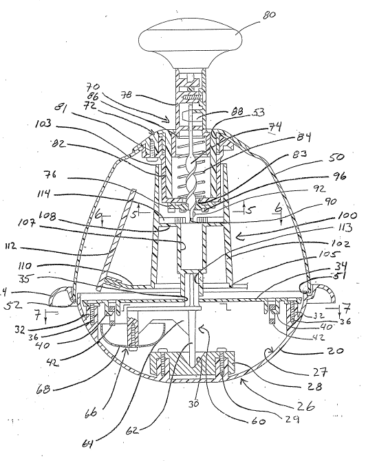
Referring to Figures 1 -and 3, the toy
carousel 10 oE the present invention includes a
base 20, a transparent dome 50, a rotation
assembly 60, a drive mechanism 70, and a display
assembly 100.
As shown in Figure 1, the base 20 has a
convex external surface 22 for contacting a
support surface 8. The upper end of the base 20
terminates at an annular flange 2~. Referring to
Figure 2, the flange 24 includes a plura].ity of
spaced arcuate apertures 25. The internal surface
of the base defines a substantially hemispherical
cavity 27. The base 20 includes a stationary
weight 28 attached to base 20 by suitable
fasteners 29 (screws) and forms a weighted bottom
26 sufficient to self-right the base to a stable,
upright position. In the upright position, as
shown in Figure 1, the base 20 is stable and
defines a central axis 6 coincident with the
vertical projection of the center of gravity of
the base 20. In the stable position, the axis 6
extends vertically from the support surface 8
through the center of gravity of the base 20. As
the base 20 oscillates, or wobbles abou-t the
stable position, the central axis 6 is
--3--
3 ~ ~
correspondingly displaced ~rom the vertical
orientation. In the stable configuration, the
center of gravity of the toy 10 is located
vertically above the point of contact between the
base 20 and the support surface 8. That is, the
center of gravity of the toy 10 is located on the
central axis and within the projection of the
convex portion of the base when the toy is in the
stable upright position, such that when the toy is
displaced from the stable upright position in
which the central axis is substantially vertical,
the toy will oscillate about the upri~ht stable
position. The base includes a flattened portion
29 concentric with the central axis 6. The
flat-tened portion 29 enhances the stability of the
toy 10 in the stable upright position.
The function of the weighted bottom 26 may be
achieved by constructing the bottom portion of the
base 20 from a volume of sufficiently dense
material (not shown) or concentrically affixing
the stationary weight 28 to the internal surface
of the bottom of the base. The stationary weight
28 includes a conical bearing surface 30
concentric with the base 20 and the central axis
6. The internal surface of the base 20 also
includes inner bosses 32 defining a common plane
between the bottom of the base and the flange 24.
The base 20 may be formed from a thermoplastic
materials such as styrene. A preferred material
is high impact styrene.
Referring to Figure 3, a circular platform 34
is disposed on the bosses 32 and may be secured to
the base by means well known in the art, such as
adhesives, fasteners, or screws 36. The platform
34 includes an aperture 35 concentric with the
3 2 ~
central axis 6. The underside of the platform
includes a pair of depending brackets 40 disposed
on a common diameter. A metallic striker 42 is
secured in each bracket 40 such that the striker
may be vertically displaced within the bracket.
As shown in Figures l, 2 and 3, the dome 50
is secured to the base 20 at the flange 24 and is
preferably a transparent plastic material, such as
buterate. The dome 50 includes an open bottom 51,
having a plurality of peripheral tabs 52. The
tabs 52 are received within apertures 25 of the
flange 24 and loc~ the.dome 50 to the base 20.
The upper end of the dome 50 includes a central
aperture 53 concentric with the axis 6.
Referring to Figures 3 and 7, the rotation
assembly 60 includes a shaft 62, a rnounting arm
64, and an eccentric weight 66. The bottom of the
shaft 62 is disposed in the bearing surface 30 of
the stationary weight 28 and is rotatable relative
to the stationar~ weight and the base 20. The
shaft 62 extends upwardly through the platform 34
to terminate a~ove the platform. Therefore, the
shaft 62 is concentric with the central axis 6.
As shown in Figures 3 and 7, the upper end of
the shaft 62 is slzed to cooperatively engage the
display assembly lO0. The upper end of the shaft
62 has an "X-shaped" cross section. Although the
shaft 62 is shown as independently rotatable
relative to the base 20, the shaft 62 may be fixed
relat1ve to the base 20, wherein the display
assembly and eccentric weight rotate about the
shaft.
The moun-ting arm 64 is affixed to the
shaft 62 beneath the platform 34 and extends
radially from the shaft. The eccentric weight 66
_5 _
2~32~
is affixed to the outer end of -the arm 64.
Preferably, the weigh-t 66 is a bell 68, such that
upon rotation of the bell about the central axis
6, the bell contacts the depending strikers 42.
Although the weight of the bell 66 is employed as
the eccentric weight, the eccentric weight 66 may
be a dummy weight at the end of -the arm 64. The
arm 64 provides rotation of the weight 66 in a
plane transverse to the central axis 6.
~lternatively, the bell 68 may be omitted and the
display assembl~ 100 may be eccentrically weighted.
The self-righting weighting of the base 20 to
the upright po.sition produces a sufficiently large
righting force so that the relative stationary
position of the eccentric weight 66 does not
prevent the base from self-righting to a stable,
substantially upright position wherein the
flattened portion 29 contacts the support
surface 8.
Referring to Figure 3, the drive mechanism 70
is retained in the central aperture 53 of the
dome 50, and includes a drive housing 72, a
helical rod 74, a pawl 76, a plunger 78, and a
knob 80. The drive housing 72 is affixed to the
dome 50 and depends downward into the volume
defined by the dome. The drive housing 72 is
secured to the dome 50 by adhesives or fasteners
81 so that the drive housing does not move
relative to the dome. The drive housing 72
includes a depending cup 82 having a concentric
aperture 83 in the bottom. The plunger 78 is
slidably received within the cup 82 and is biased
upwardly by a compression spring 84. The
compression spring 84 is disposed between the
bottom of the cup 82 and the plunger 78. Upward
2~32~
motion of the plunger 78 relative to the drive
housing 72 is limited by contact oE shoulder 86
with the drive housing.
As shown in Figures 3 and 4, the helical rod
74 is affixed to the plunger 78 and extends
downward through the aperture 83 in the bottom of
the cup 82. As shown in Figure 4, the plunger 78
includes a yoke 88 sized to receive a constricted
length 75 of the helical rod 74. Engagement of
the helical rod 74 and the plunger 78 precludes
rotation of the rod relative to the plunger 78.
Referring to Figure 3, when the plunger 78 is
in the full upward position, the helical rod 74
termi~ates at a terminal end 90 below the bottom
of the drive housing 72. The pawl 76 is disposed
on the length of helical rod 74 which depends
below the drive housing 72. The terminal end 90
includes a retaining pin or bump 92 to prevent the
pawl 76 from disengaging the rod 74. Referring to
Figures 3 and 5, the pawl 76 includes a plurality
of depending teeth 96 and a contact aperture 97.
The contact aperture 97 causes the panel 76 to
follow the helical length of the rod, so that as
the helical rod passes longitudinally through the
contact aperture, the pawl rotates relative to the
rod 74. As shown in Figure 5, the contact
aperture 97 defines-a figure eight periphery
wherein the cons-tricted portion of the periphery
contacts the middle of the width of the helical
rod 74. By providing a range of movement for the
lateral edges of the helical rod 74 within the
contact aperture 97, the pawl 76 smoothly tracks
the helical rod, as discussed infra.
Referring to Figures 1-3, the display
assembly 100 includes a central drum 102 having an
--7--
2~ 32~
upper end 103 and a lower end 105, a central
recess 107 open to the upper end, a ratchet
shoulder 108 within -the central recess, a
plurality of radial arms 110, a plurality of
display figures 112, and a coupler recess 113 open
to the lower end. The display assembly 100 is
concentrically aligned with the drive mechanism 70
and the central axis 6 as the coupler recess 113
receives the upper end of the support shaft 62.
As shown in Figure 7, the coupler recess 113 may
have a square cross section sized to receive the X
cross section of the shaft diagonally within the
recess.
Referring to Figure 3, the central recess 107
has a sufficient depth such that upon full
downward motion of the helical rod 74 relative to
the drive housing 72, the helical rod does not
contact the drum 102. As shown in Figures 3
and 6, the ratchet shoulder 108 extends radially
inward from the periphery of the drum 102, and is
concentric with the central axis 6. The shoulder
108 includes a plurality of upwardly extending
radial teeth 114 sized to engage the pawl 76. The
lower end 105 of the drum 102 is disposed proximal
to ~he platform 34. The radial arms 110 extend
from the lower end 105 and include the display
figures 112 at the terminal ends. When the bell
68 is employed as the eccentric weight 66, the
. display igures 112 are concentrically disposed
about the axis 6 (as shown in Figure 2). If the
eccentric weight 66 is not embodied in the display
assembly 100, the figures 112 may be unequally
weighted or eccentrically mounted about the axis 6
(not shown).
As the drive mechanism 70 is normally biased
2~32~
out of operable engagement with the display
assembly 100, the shaft 62, the eccentric weight
66 and the display assembly 100 can rotate freely
with respect to the base 20 and the dome 50.
Operation of the Toy:
The display assembly 100 is freely rotatable
with the shaft 62;and may be rotated by either of
two methods. The first method rotates -the display
assembly 100 due to reorientation of the eccen-tric
weight 66 rela-tive to the base 20. The second
method employs the drive mechanism 70 to rotate
the display assembly 100.
In the first method, rotation of the
eccentric weight 66 relative to the base 20 is
accomplished by displacing the base from the
stable upright position. As the base 20 is
displaced from the upright, stable position, the
eccentric weight 66 rotates about the central
axis 6 to occupy the lowest available position in
the orbit about the central a~is. The eccentric
weight 66 rotates to the lowest available position
relative to the contact surface to minimize its
potential energy. As the eccentric weight 66
rotates, the shaft 62 rotates, thereby rotating
the display assembly 100. Therefore, rocking the
base 20 about the stable upright position causes
the eccentric weight 66 to rotate the shaf~ 62 and
display assembly 100 as the weight seeks the
lowest available elevation relative to the support
surface 8.
Alternatively, the drive mechanism 70 may be
used to selectively rotate the display assembly
100. The rotation of the display assembly 100 is
achieved by a vertical reciprocating mo-tion of the
35 knob 80 and plunger 78. When the knob 80 and
_9_
2~3~
plunger 78 are depressed, the helical rod 74 is
urged downward against the bias of the compression
spring 84. As the helical rod 74 is displaced
downwardly in -the central recess 107, the pawl 76
is driven downward to operably engage the ratchet
shoulder 108. Further downward displacemen-t of
the helical rod 74 causes the helical portion to
engage the contact aperture 97, thereby inducing
rotation of the pawl. The rotation of the pawl 76
is transmitted to the drum 102, thereby rotating
the display figures 112.
Upon termination of the downward ~orce upon
the knob 80, the upward bias of -the spring 84
urges the plunger 78 upward, which draws the
helical rod 74 upward. The upward motion of the
helical rod 74 disengages the pawl 76 from the
ratchet shoulder 108. Upon disengagement of the
pawl 76 the display assembly lO0 continues to
rotate freely until frictiona]. forces terminate
rotation.
When the display assembly lO0 is rotated by
ei-ther method, the bell 68 or eccentric weight
cause the base 20 to wobble, or oscilla-te about
the stable upright position. In addition, the
rotating bell 68 contacts the depending
strikers 42, which ring the bell to produ~e
pleasing musical tones.
While a preferred embodiment of the invention
has been shown and described with particularity,
it will be appreciated that various changes and
modifications may sugyest themselves to one having
ordinary skill in the art upon being apprised of
-the present invention. It is intended to
encompass all such changes and modifications as
fall within the scope and spirit o~ the appended
claims.
-10 -