Note: Descriptions are shown in the official language in which they were submitted.
- ' I 20644~6
VARIABLE IMPEDANCE TRANSFORMER
BACKGROUND OF THE INVENTION
Field of the Invention
This invention relates to a variable impedance trans-
former, and more specifically to a method and means forminimizing an alternating voltage induced in control wind-
ings.
Prior Art Statement
Saturable reactors, and more specifically variable
impedance transformers provide an extremely rugged, substan-
tially maintenance free means to control large amounts of
AC power delivered to large lighting loads, heavy duty elec-
tric motors and the like. The high secondary AC power
levels are controlled by relatively low DC control power
levels wherein the DC control power establishes levels of
magnetic flux saturation in appropriate cores proportional
to the required AC power output level as is well known to
those skilled in the art. Offsetting these desirable char-
acteristics are some disadvantages in using these systems.
The variable impedance transformer is bulky, heavy, and has
a relatively slow response time when compared to other power
control systems. A final problem encountered with saturable
reactors, and more particularly a variable impedance trans-
former is the alternating voltage induced in the DC control
windings by the magnetic flux within the AC primary wind-
ings/ DC control winding common core(s).
The induced alternating voltage in the DC control wind-
ings places restrictions on the design and operation of the
DC control power source. Designers have attempted to solve
this deficiency by installing bulky heat sinks, large semi-
conductors and resistors in parallel with the control wind-
ings. Various resistance-capacitance solutions have been
described and some designers have attempted to solve this
problem by placing a plurality of opposed DC control wind-
ings on the control core such that the induced AC voltagescancel each other. In another system, a plurality of AC
primary winding/DC control winding common cores are oriented
2 20S4446
in a manner such that the magnetic flux of a first core
flows in opposition to the magnetic flux of a second core
proximate the DC control winding thereby having a substan-
tially canceling effect of the magnetic fluxes thereby
minimizing the induced AC voltage in the DC control winding.
U. S. Patent 2,498,475 to John Q. Adams teaches a satu-
rable magnetic core with a core construction possessing a
characteristic of constant permeability over a specified
range of magnetomotive force. Utilizing a two section core
assembly with a DC polarizing coil around a first section
of the core assembly such that the algebraic sum of the
magnetization curves of the polarized and unpolarized core
sections is a straight line.
U. S. Patent 2,586,657 to William J. Holt, Jr. teaches
a variable voltage transformer for controlling a load volt-
age by means of an adjustable DC voltage applied to a DC
control winding. The device utilizes a plurality of cores
with two primary windings, each of the primary windings is
simultaneously wound about a secondary core and a saturable
core. A secondary winding is wound about each of the sec-
ondary cores and the secondary windings are connected in
parallel to the load. The DC control winding is wound about
both of the saturable cores for controlling the flux level
in each of the saturable cores. A flux is induced in each
of the saturable cores which are positioned proximate each
other by means of an AC voltage applied to the primary
windings. The fluxes are opposite and equal to each other,
thereby canceling each other and thereby producing substan-
tially zero or little induced AC voltage in the control
winding.
U. S. Patent 2,870,397 to Fred W. Kelley, Jr. teaches
an improved saturable core apparatus utilizing three cores
with two of the cores being saturable by means of a DC
control source and the third core acting as a flux conductor
for a primary input and secondary output transformer. Two
primary windings are wound about the third core in parallel
with opposing diodes or rectifiers placed in the path of the
20~4446
primary windings so that the windings only conduct during
alternate half cycles of an AC wave.
U.S. Patent 3,087,108 to Domonic S. Toffolo teaches the
efficient transfer of power from a source to a load which
can operate at 500 degrees Fahrenheit. This device uses a
primary, secondary core and a control core, with the primary
winding being simultaneously wound about both the primary
and secondary cores, the secondary output winding being
wound about the secondary core, and the control core about
which the control winding is wound. The control winding and
contro] core are at right angles to the primary core with
an air gap existing between the control winding core and the
solid primary core. In operation the effect of the magnetic
flux in the right angle control core produces a saturation
in the primary core whereby the AC produced flux flows
proportionally through the secondary core, subsequently
inducing a voltage in the secondary output winding.
U. S. Patent 3, 123,764 to Henry W. Patton teaches the
construction of a magnetic amplifier and control device.
The signal is impressed on three windings wound about a plu-
rality of cores with the output being taken from two of the
cores with a third core being a nonsaturating member for
generating a counter electromotive force in the signal input
winding to modify the effects of distributive capacitance
currents in the amplifier circuit.
U. S. Patent 3,221,280 to James S. Malsbary et al
teaches a saturable reactor which does not require divided
reactance or control windings to prevent flow of induced AC
of the supply frequency in the control winding and is also
used in a polyphase system with a minimum number of separate
windings. The patent further teaches a three phase system
utilizing the loads being in series with the load windings
on the cores and each phase of the power supply around which
a single control winding surrounds all three phase cores and
a fourth core called an auxiliary magnetic core. In a bal-
anced three phase circuit the algebraic sum of the magnetic
flux is equal to zero. If the loads become unbalanced, the
2064446
flux becomes unbalanced which then produces a current in the
control windings. The unbalanced flux produces a current
in the auxiliary core which opposes and substantially can-
cels the current in the control core.
U. S. Patent 3,505,588 to Elwood M. Brock teaches a
load impedance responsive feedback system for a variable
reactance transformer. The variable transformer has three
cores, and primary, secondary, control, and feedback wind-
ings. A secondary winding and a feedback supply winding are
wound on the secondary winding, while the two auxiliary
cores carry DC external control and DC feedback control
windings. The primary winding is wound around all three
cores.
U. S. Patent 3,343,074 to Elwood M. Brock teaches a
variable reactance transformer having two saturable cores.
The variable reactance transformer has two saturable cores
with control windings, a power core with secondary output
winding and a primary winding surrounding all three cores
and is wound on top the DC and secondary windings. This
device uses control windings wound in series opposition
thereby creating a bucking current for any induced voltage
in the control windings by the primary current flux. Any
residual voltage component is dropped across a shunting
resistor in parallel with the two control windings.
U. S. Patent 4,129,820 to Elwood M. Brock teaches a
variable reactance transformer having a main core and a pair
of auxiliary cores whereby the auxiliary cores carry the DC
control windings which are divided in that a first winding
is wound about the core and a second coil is wound about the
first coil and wherein all the control coils are wound in
series and in a configuration such that the induced voltages
are substantially zero.
U. S. Patent 4,574,231 to Donald W. Owen teaches a
magnetic amplifier apparatus for balancing or limiting volt-
ages or currents. The apparatus comprises of a first levelof magnetic amplifiers which are responsive to a DC control
signal. The output of the first level magnetic amplifier
- 5 20~4446
provides an input signal for a second level of magnetic
amplifiers having gate windings to which the alternating
current to be controlled is connected.
Although the above stated devices provide control of
AC power by means of a DC control signal, all of the devices
suffer from a deficiency in that the devices allow an AC
voltage to be induced in the DC control windings.
The adverse effects of the induced AC voltage in DC
control windings are well known to those skilled in the art.
The AC voltages require added considerations to be made in
the design and construction of the DC windings and power
supplies. Should the AC voltages exist at substantial
levels, the counter EMF developed in the DC windings by the
AC voltages could not only prevent saturation of the magnet-
ic core of the saturable reactor but severely damage compo-
nents in the D.C. control circuit. Winding wire sizes and
the number of windings become design constraints, and power
supplies require large semiconductors or heat sinks to
absorb the effects of the AC voltage, adding to unit weight
and cost. Elimination of the induced AC voltage allows
greater flexibility in both the saturable reactor and asso-
ciated power supply designs. When no longer constrained by
the induced AC voltage the designer may use as many turns
as practical in control windings and size the wire to obtain
the resistance required for the correct control current.
Although attempts to eliminate the undesirable effects of
the induced AC voltage in the DC control windings has met
with limited success none of the above stated devices has
substantially eliminated the unwanted AC voltage. Non-
significant differences or variations in cores and windingsare sufficient to produce low levels of induced AC voltages
in DC windings.
Therefore, it is an object of the present invention to
provide an improved variable impedance transformer for con-
trolling the power from an alternating input power sourceto a load in accordance with a direct current control sig-
nal.
- 2064446
Another object of this invention is to provide an im-
proved variable impedance transformer wherein the first and
second saturable reactor cores and the first and second
power input windings are established and positioned to
substantially cancel the magnetic flux proximate the control
winding.
Another object of this invention is to provide an im-
proved variable impedance transformer wherein an equalizing
winding is simultaneously wound about the first and second
saturable reactor cores for shunting any resultant alter-
nating voltage induced by any residual magnetic flux as a
result of non-substantial physical variations between the
first and second saturable reactor cores.
The foregoing has outlined some of the more pertinent
objects of the present invention. These objects should be
construed as being merely illustrative of some of the more
prominent features and applications of the invention. Many
other beneficial results can be obtained by applying the
disclosed invention in a different manner or modifying the
invention with in the scope of the invention. Accordingly
other objects in a full understanding of the invention may
be had by referring to the summary of the invention, the de-
tailed description describing the preferred embodiment in
addition to the scope of the invention defined by the claims
taken in conjunction with the accompanying drawings.
206~446
_ 7
SUMMARY OF THE INVENTION
The present invention is defined by the appended claims
with specific embodiments being shown in the attached draw-
ings. For the purpose of summarizing the invention, the
invention relates to a variable impedance transformer, and
more specifically to an improved method and apparatus for
minimizing an alternating voltage induced in control wind-
ings. The variable impedance transformer for controlling
power from an alternating input power source to a load in
accordance with a direct current control signal is provided
with a first and a second saturable reactor core and power
core means. First and second power input windings are
simultaneously wound about the power core means and the
first and second saturable reactor cores, respectively. A
means connecting the first and second power input windings
in parallel across the alternating input power source is
provided for establishing a magnetic flux in the power core
means and for establishing a magnetic flux in the first and
second saturable reactor cores. A power output means wind-
ing for transferring power to the load is wound about thepower core means and a control winding is wound about the
first and second saturable reactor cores for controlling
saturation of the magnetic flux in the first and second
saturable reactor cores in accordance with the direct cur-
rent control signal. The first and second saturable reactorcores and the first and second power input windings are
established and positioned to substantially cancel the
magnetic flux proximate the control winding. An equalizing
winding is wound about the first and second saturable reac-
tor cores for shunting any resultant alternating voltageinduced by any residual magnetic flux as a result of non-
substantial physical variations between the first and second
saturable reactor cores.
Preferably, the equalizing winding is connected to a
low impedance or is shorted for neutralizing any resultant
alternating voltage induced by the first and second satura-
ble reactor cores. In one embodiment of the invention, the
20~4~46
. 8
control winding has a substantially greater number of turns
than the equalizing winding.
The first and second saturable reactor cores and the
first and second power input windings are substantially
identical to one another for substantially canceling the
magnetic flux proximate the control winding. Each of the
first and second saturable reactor cores and the power core
means provides a closed loop for the magnetic flux.
In another embodiment of the invention, the power core
means comprises a first power core with a first power input
winding being simultaneously wound about a first power core
and a first saturable reactor core. A second power input
winding is simultaneously wound about the first power core
and a second saturable reactor core. The power output
winding means comprising a first power output winding wound
about the first power core.
In another embodiment of the invention, the power core
means comprises a first and second power core with the first
power input winding being simultaneously wound about the
first power core and the first saturable reactor core and
a second power input winding being simultaneously wound
about a second power core and a second saturable reactor
core. A means is provided for connecting the first and
second power input windings across the alternating input
power source establishing a magnetic flux in the first and
the second power cores propagating in the same direction.
A power output winding means is provided comprising a first
power output winding wound about the first power core and
a second power output winding wound about the second power
core. A means connecting the first and second power output
windings is provided, wherein the first and second power
output windings are connected in parallel.
In another embodiment of the invention, the power core
means comprises a first and second power core with the first
^~ power input winding being simultaneously wound about the
first power core and the first saturable reactor core and
a second power input winding being simultaneously wound
206~446
.. g
about a second power core and a second saturable reactor
core. A means is provided for connecting the first and
second power input windings across the alternating input
power source establishing a magnetic flux in the first and
the second power cores propagating in the opposing direc-
tion. A power output winding means is provided comprising
a first power output winding wound about the first power
core and a second power output winding wound about the
second power core. A means connecting the first and second
power output windings is provided, wherein the first and
second power output windings are connected in parallel.
The invention is also incorporated into the method of
reducing a residual alternating voltage across a control
winding of a variable impedance transformer having a first
and a second saturable reactor core and a power core means.
The method details the winding of identical first and second
power input windings about the power core means and the
first and second saturable reactor cores, respectively, as
well as, winding a control winding about the first and
second saturable reactor cores, and winding an equalizing
winding about the first and second saturable reactor cores.
The invention further describes connecting the equalizing
winding to a low impedance for absorbing any residual alter-
nating voltage induced between the first and second satura-
ble reactor cores due to physical variations therebetween.
The foregoing has outlined rather broadly the more per-
tinent and important features of the present invention in
order that the detailed description that follows may be
better understood so that the present contribution to the
art can be more fully appreciated. Additional features of
the invention will be described hereinafter which form the
subject of the claims of the invention. It should be appre-
ciated by those skilled in the art that the conception and
the specific embodiments disclosed may be readily utilized
as a basis for modifying or designing other structures for
carrying out the same purposes of the present invention.
It should also be realized by those skilled in the art that
206~446
-- 10
such e~uivalent constructions do not depart from the spirit
and scope of the invention as set forth in the appended
claims.
2064446
11
BRIEF DESCRIPTION OF THE DRAWINGS
For a fuller understanding of the nature and objects
of the invention, reference should be made to the following
detailed description taken in connection with the accompany-
ing drawings in which:
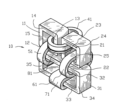
FIG. 1 is an isometric view of a first embodiment of
a variable impedance transformer incorporating the present
invention;
FIG. 2 is a circuit representation of the first embodi-
ment of the variable impedance transformer illustrating themagnetic flux directions during a first half cycle of an
alternating current wave;
FIG. 3 is a circuit rep-esentation of the first embodi-
ment of the variable impedance transformer illustrating the
magnetic flux directions during a second half cycle of an
alternating current wave;
FIG. 4 is an schematic diagram of the first embodiment
of the present invention shown in FIGS. 1-3 connected to an
alternating current source;
FIG. 5 is an equivalent circuit diagram of the circuit
of FIG. 4;
FIG. 6 is a graph of an offset voltage as a function
of the number of turns of the equalizing winding.
FIG. 7 is an isometric view of a second embodiment of
a variable impedance transformer incorporating the present
invention;
FIG. 8 is a circuit representation of the second em-
bodiment of the variable impedance transformer illustrating
the magnetic flux directions during a first half cycle of
3 n an alternating current wave;
FIG. 9 is a circuit representation of the second em-
bodiment of the variable impedance transformer illustrating
the magnetic flux directions during a second half cycle of
an alternating current wave;
FIG. 10 is an isometric view of a third embodiment of
a variable impedance transformer incorporating the present
invention;
2064446
~ 12
FIG. 11 is a circuit representation of the third em-
bodiment of the variable impedance transformer illustrating
the magnetic flux directions during a first half cycle of
an alternating current wave;
FIG. 12 is a circuit representation of the third em-
bodiment of the variable impedance transformer illustrating
the magnetic flux directions during a second half cycle of
an alternating current wave;
FIG. 13 is an isometric view of a fourth embodiment of
a variable impedance transformer incorporating the present
invention; and
FIG. 14 is a circuit representation of the fourth
embodiment of the variable impedance transformer.
Similar reference characters refer to similar parts
throughout the several Figures of the drawings.
2064446
_ 13
DETAILED DISCUSSION
Fig. 1 is an isometric view of a first embodiment of
the present invention illustrating a variable impedance
transformer 10. Fig. 2 and Fig. 3 are circuit representa-
tions of the first embodiment of the variable impedancetransformer 10 illustrating magnetic flux directions during
a first half cycle and a second half cycle of an alternating
current wave. The variable impedance transformer 10 in-
cludes a first and a second saturable reactor core 11 and
21 shown as closed loop square cores with a rectangular
cross section. The first saturable reactor core 11 com-
prises first, second, third and fourth legs 12, 13, 14, and
15 respectively. The second saturable reactor core 21 com-
prises first, second, third and fourth legs 22, 23, 24, and
25 respectively. A power core 31 has first, second, third
and fourth legs 32, 33, 34, and 35. The power core 31 is
shown as a rectangular closed loop core with a rectangular
cross section.
The saturable reactor cores 11 and 21 and power core
31 are of conventional core construction being fabricated
from a plurality of substantially planar lamination compris-
ing a material with a high magnetic permeability including
ferromagnetic elements or alloys thereof. For the purposes
of illustration variable impedance transformer 10 is shown
as an open air cooled assembly, however encapsulation of the
variable impedance transformer lO may be utilized as well
as providing a water cooling means (not shown).
Since the variable impedance transformer lO of the
present invention, may be designed for operation from less
than one hundred volt-amperes to several thousands of volt-
amperes in capacity, the input and the output voltages, the
frequency of operation, and the current capacity constitute
design variable of the variable impedance transformer 10.
A DC control winding 41 having a first end 42 and a
second end 43 is wound simultaneously about the second legs
13 and 23 of the first and the second saturable reactor
cores 11 and 21. A first power input winding 51 having a
20644~6
_ 14
first end 52 and a second end 53 is wound simultaneously
about the first leg 32 of the power core 31 and the first
leg 12 of the first saturable reactor 11. A second power
input winding 61 having a first end 62 and a second end 63
is wound simultaneously about the first leg 32 of the power
core 31 and the first leg 22 of the second saturable reactor
21. A power output winding 71 having a first end 72 and a
second end 73 is wound about the second leg 33 of the power
core 31.
The variable impedance transformer 10 as heretofore
described is a conventional variable impedance transformer
as should be well known to those skilled in the art. In
accordance with the prior art practice, a substantial effort
is made to construct the first and second saturable reactor
cores 11 and 21 to be identical to one another to produce
the same resultant magnetic flux from the first and the
second power input windings 51 and 61. In addition, the
first and second saturable reactor cores 11 and 21 are
established relative to one another such that magnetic flux
in the second leg 13 of the first saturable reactor core 11
opposes or cancels the magnetic flux in the second leg 23
of the second saturable reactor core 21. These prior art
construction techniques sought to eliminate an AC voltage
from being induced into the control winding 41. Since it
is difficu].t to construct the first and second saturable
reactor cores 11 and 21 in an identical manner, and for
numerous other reasons, the prior art technique has only
reduced the level of the AC voltage in the control winding
41.
To overcome this problem, the present invention incor-
porates an equalizing winding 81 having a first end 82 and
a second end 83. The equalizing winding 81 is wound simul-
taneously about the second legs 13 and 23 of the first and
the second saturable reactor cores 11 and 21. The first and
second ends 82 and 83 of the equalizing winding 81 are
either shorted or are connected to a low impedance 84.
Preferably, the number of turns in the equalizing winding
20~4446
_ 15
81 is substantially less than the number of turns in the DC
control winding 41. As will be described in greater detail
hereinafter, the equalizing winding 81 solves the problems
encountered by the prior art.
In accordance with the prior art practice, a wide
variety of conductor dimensions may be utilized in construc-
tion of the variable impedance transformer 10 including the
DC control winding 41, the equalizing winding 81, the first
and second power input windings 51 and 61 and the power
output winding 71. The conductor dimensions include the
number of turns per winding and the winding cross-section.
The winding cross-section may vary from fine insulated
round, gquare to rectangular wire or insulated foil to
metallic tubing as should be well known to those skilled in
the art.
FIG. 4 is an schematic diagram of the variable imped-
ance transformer 10 of FIGS. 1-3 connected to an alternating
current power supply 88. The schematic diagram of FIG. 4
is a simplified method for manually controlling the power
to the load 86 from the variable impedance transformer 10.
It should be appreciated by those skilled in the art that
the schematic diagram of FIG. 4 is not to be interpreted as
the normal method of controlling the output power of the
variable impedance transformer 10. Typically, the variable
impedance transformer 10 is controlled by feedback circuits,
computers or the like for maintaining the power to the load
86 at a desired level.
The alternating current power supply 88 is connected
to the first and second ends 52 and S3 of the first power
input winding 51 and is connected to the first and second
ends 62 and 63 of the second power input winding 61.
The first and second ends 72 and 73 of the power output
winding 71 are connected to a load 86. The load 86 may be
a furnace or lighting equipment or the like typically having
a substantial operating current requirement with a signifi-
cantly higher surge current required during the start of the
circuit.
20B44~6
~ 16
The alternating current power supply 88 is connected
to a variable auto transformer 90 having a variable voltage
tap 91 with the variable voltage tap 91 being connected to
an input winding 92 of a voltage reduction transformer 94.
An output winding 96 of the voltage reduction transformer
94 is connected to a DC bridge 98 for supplying a variable
DC voltage to the first and second ends 42 and 43 of the
control winding 41. A resistor 100 functions to limit the
current through the control winding 41 whereas a capacitor
102 functions as a filter.
The variable impedance transformer 10 of the present
invention operates in a manner similar to a conventional
variable impedance transformer. The variable voltage tap
91 of the voltage reduction transformer 94 is positioned to
supply a minimum DC voltage to the control winding 41. When
the AC power supply 88 is activated, an alternating current
flows through the first and the second power input windings
51 and 61 to establish a magnetic flux flow in the power
core 31. In addition, alternating current flow through the
first and the second power input windings 51 and 61 estab-
lishes a magnetic flux flow in the first and second satu-
rable reactor cores 11 and 21.
Since the magnetic flux established by the current flow
through the first and second input windings 51 and 61 is
divided between the power core 31 and the first and second
saturable reactor cores 11 and 21, the power transferred
through the power core 31 and the output winding 71 to the
load 86 is substantially reduced. The amount of the power
reduction is dependent upon construction parameters includ-
ing winding turns and core construction between the powercore 31 and the first and second saturable reactor cores 11
and 21. The reduction of power transferred through the
power core 31 and the output winding 71 to the load 86
compensates for the significantly higher surge current re-
quired during the start of the load 86.
As the variable voltage tap 91 of transformer 94 ispositioned to supply a DC voltage to the control winding 41,
2064446
_ 17
an additional magnetic flux is established in the first and
second saturable reactor cores 11 and 21. The additional
magnetic flux established in the first and second saturable
reactor cores 11 and 21 results in an increase in the level
of magnetic flux flow in the power core 31 and an increase
in the power transferred through the power core 31 and the
output winding 71 to the load 86.
As the variable voltage tap 91 of transformer 94 is
positioned to supply additional DC voltage to the control
winding 41, the magnetic flux in the first and second satu-
rable reactor cores 11 and 21 reaches magnetic flux satura-
tion. When the magnetic flux in the first and second satu-
rable reactor cores 11 and 21 reaches a saturation level,
substantially all the magnetic flux flow established by the
first and second power input windings S1 and 61 is estab-
lished in the power core 31. Accordingly, substantially all
of the power from the first and second power input windings
51 and 61 is transferred through the power core 31 and the
output winding 71 to the load 86.
If the first and second ends 72 and 73 of the power
output winding 71 of the variable impedance transformer 10
are connected to a load 86 such a furnace or lighting equip-
ment or the like typically having a substantial operating
current, the variable voltage tap 91 of the voltage reduc-
tion transformer 94 is positioned to supply a minimum DC
voltage to the control winding 41. When the AC power supply
88 is activated, the high impedance provided by the first
and second saturable reactor cores 11 and 21 limit the
current from the output winding 71 to the load 86.
Some variable impedance transformers of the prior art
have utilized the aforementioned method to cancel an induced
voltage in control winding 41. However, since precisely
identical winding placement combined with identical core
characteristics are substantially impossible to achieve in
production, non-significant differences or variations in the
cores and in the windings are sufficient to produce varying
levels of induced AC voltages in the DC control windings 41.
2~S~446
18
The variable impedance transformer 10 of the present
invention utilizes the equalizing winding 81 wound about the
second legs 13 and 23 of the first and second saturable
reactor cores 11 and 21. Preferably, the number of windings
in the equalizing winding 81 is substantially less than the
number of windings in the DC control winding 41. The first
and second ends 82 and 83 of the equalizing winding 81 may
be directly connected to one another forming a completed
electrical circuit or may be connected to a low impedance
84. The AC voltage induced as a result of non-significant
differences or variations in the cores and in the windings
is preferentially shunt dissipated by the equalizing winding
81 relative to the DC control winding 41. The AC voltage
is preferentially shunt dissipated by the equalizing winding
81 relative to the DC control winding 41 since the equaliz-
ing winding 81 is selected to have a significantly lower
impedance relative to the control winding 41. Since the AC
circulating currents produced by induced the AC voltages are
established within the equalizing winding 81, there is a
substantial reduction in the AC voltage induced in the
control winding 41. The value of the low impedance 84 may
be adjusted to reduce the circulating currents to acceptable
levels.
FIG. 5 is a substantially simplified equivalent circuit
of the variable impedance transformer 10. The simplified
equivalent circuit variable impedance transformer 10 with
the load 86 disconnected and no D.C. voltage applied to the
control windings 41. The variable impedance transformer 10
is normally designed so that the impedance of the first and
second saturable reactor cores 11 and 21 is equal to the
impedance of the power core 31. Therefore, one-half of the
input voltage 88 appears across the first and second satura-
ble reactor cores 11 and 21 and one-half of the input volt-
age 88 would appears across the power core 31.
When the load 86 is connected to the output winding 71,
the reflected impedance to the power core 31 is many times
less than the impedance of the first and second saturable
2064~46
19
reactor cores 11 and 21. The voltage across the input
windings 51 and 61 of power core 31 is substantially the
ratio of the input impedance of the power core 31 to the
impedance of the first and second saturable reactor cores
11 and 21 times the input voltage 88. Accordingly, with no
D.C. current flowing into the control windings 41, the
output power to load 86 is normally less than five percent
(5~) of the capacity of the variable impedance transformer
10. As D.C. current flows into the control winding 41, the
impedance of the first and second saturable reactor cores
11 and 21 drops allowing more voltage to appear across the
input windings 51 and 61 of power core 31. The voltage
across the input windings 51 and 61 of power core 31 pro-
gressively increases as more D.C. current flows into the
control winding 41 until saturation of the first and second
saturable reactor cores 11 and 21 is achieved. At satura-
tion, the first and second saturable reactor cores 11 and
21 become essentially resistive and substantially all of the
input voltage 88 appears across the input windings 51 and
61 of the power core 31.
The equivalent circuit is based on a test transformer
employing three Arnold AH320 cores. The specifications of
each of the cores was D=2; E=1; F=1.625 and G=4.5 and weigh-
ing 7.33 pounds. An input load resistor 104 was connected
for measuring the current through the variable impedance
transformer lo. Resistors R1 and R2 represent the equiva-
lent resistance of the first and second power input windings
51 and 61 whereas the inductance 106 is the equivalent
magnetizing core winding of the first and second power input
windings 51 and 61. Since the magnetic flux established by
the current flow through the first and second input windings
51 and 61 is divided between the power core 31 and the first
and second saturable reactor cores 11 and 21 as set forth
above, the first and second saturable reactor cores 11 and
21 appear in series with the first and second input windings
51 and 61 in the equivalent circuit of FIG. 5.
2064446
When a voltage of 8.38 volts was applied through the
input load resistor 104 of 0.257 ohms, a voltage of 0.611
volts was measured across the input load resistor 104 ohms
indicating that 2.38 amperes of current was flowing through
the first and second input windings 51 and 61. The test
transformer produced an open circuit voltage of 1.78 volts
on the output winding 71.
FIG. 6 is a graph of an offset voltage (induced AC
voltage) as a function of the number of turns of the equal-
izing winding 81. The abscissa of the graph plots the totalnumber of turns of the equalizing winding 81 as a percentage
of total number of turns of the control winding 41. The
ordinate of the graph plots the percentage of offset voltage
(induced AC voltage). With a zero turn equalizing winding
81, or the absence of the equalizing winding 81, the offset
voltage is one hundred percent (100%) for the tested vari-
able impedance transformer 10. With the introduction of an
equalizing winding 81 having only three percent (3%) of
total number of turns of the control winding 41, the offset
voltage (induced AC voltage) is reduced by almost fifty
percent (50%). When the number of turns of the equalizing
winding 81 is increased to twelve percent (12%) of total
number of turns of the control winding 41, the offset volt-
age (induced AC voltage) is reduced below twenty percent
2S (20%). When the number of turns of the equalizing winding
81 is increased to twenty-four percent (24%) of total number
of turns of the control winding 41, the offset voltage
(induced AC voltage) is reduced below ten percent (10%).
Accordingly, an equalizing winding having a small number of
turns relative to the total number of turns of the control
winding 41 provides a substantial reduction in the offset
voltage (induced AC voltage).
The present invention may be incorporated into a vari-
able impedance transformer of various designs and configura-
tions as illustrated by the second and third embodimentsshown in FIGS. 7-12. In addition, the equalizing winding
81 may be incorporated into a variable impedance transformer
~06~446
21
in various configurations as illustrated by the fourth
embodiments shown in FIGS. 13-14.
Fig. 7 is an isometric view of a second embodiment of
the present invention illustrating a variable impedance
transformer 110 having a different configuration than the
first embodiment shown in FIGS. 1-3. Fig. 8 and Fig. 9 are
circuit representations of the second embodiment of the
variable impedance transformer 110 illustrating magnetic
flux directions during a first half cycle and a second half
cycle of an alternating current wave. The variable imped-
ance transformer 110 includes a first and a second saturable
reactor core 111 and 121. The first saturable reactor core
111 comprises first, second, third, and fourth legs 112,
113, 114, and 115 respectively whereas the second saturable
reactor core 121 comprises first, second, third and fourth
legs 122, 123, 124, and 125 respectively.
In this embodiment, the power core comprises a first
power core 131 having first, second, third and fourth legs
132, 133, 134, and 135 respectively, and a second power core
136 having first, second, third and fourth legs 137, 138,
139, and 140 respectively. A DC control winding 141 having
a first end 142 and a second end 143 is wound simultaneously
about the second legs 113 and 123 of the first and the
second saturable reactor cores 111 and 121 respectively.
A first power input winding 151 having a first end 152 and
a second end 153 is wound simultaneously about the first leg
132 of the first power core 131 and the first leg 112 of the
first saturable reactor core 111. A second power input
winding 161 having a first end 162 and a second end 163 is
wound simultaneously about the first leg 137 of the second
power core 136 and the first leg 122 of the second saturable
reactor core 121. A first power output winding 171 having
a first end 172 and a second end 173 is wound about the
second leg 133 of the first power core 131 whereas a second
power output winding 175 having a first end 176 and a second
end 177 is wound about the second leg 138 of the second
power core 136. An equalizing winding 181 having a first
206~446
~ 22
end 182 and a second end 183 is wound simultaneously about
the second legs 113 and 123 of the first and the second
saturable reactor cores 111 and 121 respectively. The first
and second ends 182 and 183 of the equalizing winding 181
are connected to the low impedance 184.
The variable impedance transformer 110 of the second
embodiment of the invention shown in FIGS. 7-9 operates in
a manner similar to the operation of the variable impedance
transformer 10 of the first embodiment of the invention
shown in FIGS. 1-3.
The AC voltage induced as a result of non-significant
differences or variations in the cores and the windings is
preferentially shunt dissipated by the equalizing winding
181 relative to the DC control winding 141 providing a
substantial reduction in the AC voltage induced in the
control winding 41.
Fig. 10 is an isometric view of a third embodiment of
the present invention illustrating a variable impedance
transformer 210 having still a different configuration than
the first and second embodiment shown in FIGS. 1-3 and 7-9.
Fig. 11 and Fig. 12 are circuit representations of the third
embodiment of the variable impedance transformer 210 illus-
trating magnetic flux directions during a first half cycle
and a second half cycle of an alternating current wave. The
variable impedance transformer 210 includes a first and a
second saturable reactor core 211 and 221. The first satu-
rable reactor core 211 comprises first, second, third, and
fourth legs 212, 213, 214, and 215 respectively, whereas the
second saturable reactor core 221 comprises first, second,
third, and fourth legs 222, 223, 224, and 225 respectively.
A first power core 231 includes a first, second, third
and fourth legs 232, 233, 234, and 235 respectively, whereas
a second power core 236 includes a first, second, third and
fourth legs 237, 238, 239, and 240 respectively. A DC
control winding 241 having a first end 242 and a second end
243 is wound simultaneously about the second legs 213 and
223 of the first and the second saturable reactor cores 211
206~446
_ 23
and 221 respectively. A first power input winding 251
having a first end 252 and a second end 253 is wound simul-
taneously about the first leg 232 of the first power core
231 and the first leg 212 of the first saturable reactor
core 211. A second power input winding 261 having a first
end 262 and a second end 263 is wound simultaneously about
the first leg 237 of the second power core 236 and the first
leg 222 of the second saturable reactor core 221. A first
power output winding 271 having a first end 272 and a second
end 273 is wound about the second leg 233 of the first power
core 231 whereas a second power output winding 275 having
a first end 276 and a second end 277 is wound about the
second leg Z38 of the second power core 236. An equalizing
winding 281 having a first end 282 and a second end 283 is
wound simultaneously about the second legs 213 and 223 of
the first and the second saturable reactors cores 211 and
221 respectively, with the first and second ends 282 and 283
being connected to the low impedance 284.
The variable impedance transformer 210 of the third
embodiment of the invention shown in FIGS. 10-12 operates
in a manner similar to the operation of the variable imped-
ance transformers 10 and 110 of the first and second embodi-
ments shown in FIGS. 1-3 and 7-9. The AC voltage induced
by non-significant variations in the cores and the windings
is preferentially shunt dissipated by the equalizing winding
281 providing a substantial reduction in the AC voltage
induced in the control winding 241.
The variable impedance transformer 210 of FIGS. 10-12
operates in a manner similar to the variable impedance
transformer 110 of FIGS. 7-9. In contrast to the variable
impedance transformer 110 of FIGS. 7-9, the magnetic flux
in the first power core 231 and the first saturable reactor
core 211 flows in an opposite direction relative to the
magnetic flux in the second power core 236 and the second
saturable reactor core 221 in the variable impedance trans-
former 210 of FIGS. 10-12. The opposite magnetic flux in
the first and second power cores 231 and 236 and in the
2064446
_ 24
first and second saturable reactor cores 211 and 236 is the
result of the first power input winding 251 being wound in
a direction opposite to the second power input winding 261.
The first embodiment of the variable impedance trans-
former 10 shown in FIGS. 1-3 has several advantages over the
second embodiment of the variable impedance transformer 110
shown in FIGS. 7-9 and the third embodiment of the variable
impedance transformer 210 shown in FIGS. 10-12. The first
embodiment of the variable impedance transformer 10 shown
in FIGS. 1-3 only requires a single power core 31 and first
and second saturable reactor cores 11 and 21 in contrast to
the plural power core 131 and 140 of FIGS. 7-9 and the
plural power core 231 and 240 of FIGS. 10-12. Accordingly,
the first embodiment of the variable impedance transformer
10 of FIGS. 1-3 has a reduced weight of approximately sixty-
seven percent (67%) over the second and third embodiments
of the variable impedance transformer 110 and 210.
The second and third embodiments of the variable imped-
ance transformer 110 and 210 of FIGS. 7-9 and FIGS. 10-12
have an advantage over the first embodiment of the variable
impedance transformer 10 shown in FIGS. 1-3 since the output
windings 171 and 175 of FIGS. 7-9 and the output windings
271 and 275 of FIGS. 10-12 can easily be wound inside the
input windings 151 and 161 of FIGS. 7-9 and the input wind-
ings 251 and 261 of FIGS. 10-12 to provide a superior cou-
pling between the input windings and the output windings.
Fig. 13 is an isometric view of a fourth embodiment of
the present invention illustrating a variable impedance
transformer 310 with Fig. 14 being a circuit representations
thereof. The variable impedance transformer 310 is similar
to the first embodiment shown in FIGS. 1-3 and includes a
first and a second saturable reactor core 311 and 321. The
first saturable reactor core 311 comprises a first, second,
third and fourth legs 312, 313, 314, and 315 respectively.
The second saturable reactor core 321 comprises a first,
second, third and fourth legs 322, 323, 324, and 325 respec-
tively. A power core 331 has first, second, third and
206~4~
fourth legs 332, 333, 334, and 335. A DC control winding
341 having first and second ends 342 and 343 is wound simul-
taneously about the second legs 313 and 323 of the first and
the second saturable reactor cores 311 and 321. A first
power input winding 351 having first and second ends 352 and
353 is wound simultaneously about the first leg 332 of the
power core 331 and the first leg 312 of the first saturable
reactor core 311. A second power input winding 361 having
first and second ends 362 and 363 is wound simultaneously
about the first leg 332 of the power core 331 and the first
leg 322 of the second saturable reactor core 321. A power
output winding 371 having first and second ends 372 and 373
is wound about the second leg 333 of the power core 331.
In this embodiment, the variable impedance transformer
310 comprises a first and a second equalizing winding 381
and 381A. The first and second equalizing windings 381 and
381A are independently wound about the fourth legs 315 and
325 of the first and the second saturable reactor cores 311
and 321. The first equalizing winding 381 includes first
and second ends 382 and 383 whereas the second equalizing
winding 381A includes first and second ends 382A and 383A.
The first equalizing winding 381 is wound in opposition to
the second equalizing winding 381A with a low impedance 384
interconnection the first ends 382 and 382A of the first and
second equalizing windings 381 and 381A. The second ends
383 and 383A of the first and second equalizing windings 381
and 381A are directly interconnected.
In a manner similar to the equalizing winding 81 of
FIGS. 1-3, the first and second equalizing windings 381 and
381A preferentially shunt dissipate from the DC control
winding 341, the AC voltage induced as a result of non-
significant differences or variations in the cores and the
windings. More specifically, any difference of voltage
induced within the first and second equalizing windings 381
and 381A will cancel with one another to produce a resultant
voltage within one of the first and second equalizing wind-
ings 381 and 381A. The resultant voltage within the one of
208~446
26
the first and second equalizing windings 381 and 381A will
induce a magnetic flux in opposition to the original AC flux
developed as a result of non-significant differences or
variations in the cores and the windings. Preferably, the
first and second equalizing windings 381 and 381A are se-
lected to have a significantly lower impedance relative to
the control winding 341.
It should be appreciated by those skilled in the art
that a single or multiple equalizing windings may be uti-
lized in any of the embodiments set forth herein. In addi-
tion, the use of equalizing winding may be applied to vari-
able impedance transformers of various designs and construc-
tions as well as auto transformers and the like. It should
also be appreciated by those skilled in the art that the
principals set forth herein are equally applicable to either
single phase or three phase operation.
Although the saturable reactor cores and are illus-
trated as employing substantially square closed loop cores
with rectangular cross-sections and the power core is illus-
trated as employing a rectangular closed loop core with arectangular cross-section, it should be understood that
other core configurations may be utilized within the scope
of the present invention. In addition to square and rectan-
gular cores, oval cores, torroidal cores, "C" cores, and
distributed air gap cores may be used with equal success.
The utilization of "C" cores provides a simple core winding
process prior to the joining of two 'IC'' core assemblies.
Distributed air gap cores provide the same ease of winding,
but provide a more uniform magnetic flux flow around the
closed loop core, since the air gap spaces are distributed
about the closed loop. Core cross-sections may likewise
include square, rectangular and crucifix cross-sections as
is well known to those skilled in the art.
The present disclosure includes that contained in the
appended claims as well as that of the foregoing descrip-
tion. Although this invention has been described in its
preferred form with a certain degree of particularity, it
206444~
27
is understood that the present disclosure of the preferred
form has been made only by way of example and that numerous
changes in the details of construction and the combination
and arrangement of parts may be resorted to without depart-
ing from the spirit and scope of the invention.