Note: Descriptions are shown in the official language in which they were submitted.
~47~7
WO 91/19469 PCI/U~;gl/04585
SYSTEM F~R TRE~EDT OF SP~L DEFO ~ ~IES
Field of the Invention
This application is a continuation o~ United
States Serial No. 07/540,635 filed 19 June 1990.
This invention relates generally to surgical
apparatus and methods for use in the treatment of
spinal deformities such as scoliosis and kyphosis, ;
and for internal fixation of the spine. More ;~
specifically, the invention relates to a modular
instrumentation system and method in which individual
components of a spinal rod construct may be assembled
and surgically implanted. The system and methocl of
the invention provides much greater flexibility and
ease of use for the treatmPnt o~ spinal abnormalities
such as curvature of the spine, ~ractures, and the
like, when an arthrodesis is required.
DescriPtion o~ the Prior Art
.. . . .
Spinal deformities such as scoliosis and
kyphosis, fractures and conditions which n~ed an
arthrodesis, have been treated with a variety of
apparatus and methods, including external braces and
traction apparatus, and surgical implants. Surgical
treatment o~ scoliosis, ~or instance, is generally `
indicated when the lateral deviation of the spine
exceeds certain limits. Such surgical treatment,
known as arthrodesis, involves both correction of the
curvature of the spine in the region of deviation,
and fusion by autogenous bone grafts of the vertebrae
in the region of abnormal curvature. In bone fusion
technique-¢, it is imperative that a corrected and
fixed configuration of the vertebrae be immobilized
during the period in which vertebrae are being ~-
fused. Both posterior and anterior instrumentation
'~
WO91/19469 2 ~ 6 ~ ~2 ~ PCT/U591/0~58'
--2--
has been developed for this purpose, although the
posterior instrumentation i5 generally preferred
because of the more simple surgical technique
required to implement it.
One known surgical technique for maintaining
corrected positioning of vertebrae during the fusion
process involves the attachment of rods to the spine
to obtain anatomic alignment o~ the s~pine and
immobilize the spine until arthrodesis is completed.
A variety of different types of instrumentation for
implementing this procedure have been developed in
the prior art. These prior art instrumentations
utilize some form of compression and
contraction-distraction apparatus that is applied to
the spine to straighten the curvature. In some of
these systems, the rods are secured to the spine by
use of wires passed through the vertebrae and around
the rods. Such systems are described, for example,
in Russian patent publication Nos. 1053404 A of 1983,
and 44l932 of 1974.
In other systems, staples are attached by screws
to the ventral or anterior side of the vertebrae on
the convex side of the de~ormity, and the stapled
vertebrae are interconnected by passing a cablP
through holes in .the heads of the screws. Then,
starting at one end, pairs of stapled vertebrae are
compressed by applying tension to the cable to
straighten the curve. Compression between vertebrae
is maintained by crimping the screw heads onto the
cable. This system of staples, screws and cable is
known as Dwyer instr11mentationO
Instrumentation for posterior implantation is
disclosed in U.S. Patent No. 3,565,066, in which a
rigid member bridyes a scoliotic, kyphotic, or
lordotic curve and hooks are disposed orthogonally to
the rigid member to engage and move individual
vertebrae toward the rigid member. ~ ~
-
~ v v ~ ~
WO91/19469 PCT/U~91/04~85 ,.. ~::
.
3- :~
Other instrumentation for posterior implantation .,
includas that known as Harrington instrumentation.
This system has gained the greatest acceptance, and
comprises an elongate threaded rod in combination '::
with two or more hooks that are hooked onto the
lamina of respective vertebrae and secured to the
rocl. One rod and its associated hooks may be placed
on the convex side of the deformity to apply a
compressive force to the vertebrae, while a second
rod and its associated hooks may be applied on the
contralateral side of the deformity to apply
distraction to the vertebrae. Examples of Harrington ,'
instrumentation are disclosed in U.S. Patent Nos.
4,269,178, 4,274,401, 4,361,141,~4,369,769, ':' ' '
4,369,770, 4,382,438, 4,386,603, 4,404,967, '.,
4,409,968, 4,411,259 and 4,422,451. ,'
other examples of prior art apparatus for
treatment of spinal deformities are disclosed in ,' ',
Russian patent disclosure 654,251, of 1979, and U.S. ';''
Patent Nos. 3,242,922, 4,448,191, 4,567,884 and .:~
4,611,582. : ,
As is apparent from the prior art listed above, ,;
most prior art systems use some form of elongate rod :.
and hook structure. In many of these, the hooks are :,.',,
threaded onto an elongate threaded rod so that the :;,
hooks may be moved toward and away from one another :,,'
on the rod to apply either distraction or compression :'
on the vertebrae. Some devices, as disclosed by ~' :
BLISKUNOV (Russia, 654,251, March 1979) and DUFF : :
(United States, 4,611,582), are complex mechanisms
,having multiple threaded rods concentrically engaged
on one another, and/or with ratchet mechanisms for
adjusting the spacing between hooks. ,
'
.. , . .: . . ,.. : .. ~; . , ,: : , . : . . , ~: . , , :
., , . . ~ . . ~ .. .
~,5i~ 3~ 7,~ ;,
WO91/1946g PCr/US91/~45
4--
The prior art systems have several disadvantages
incident to their use. For instance, the most widely
accepted system uses threaded rods on which hooks are
engaged for applying compression or distraction to
the vertebrae. These systems are essentially
preassembled, with a predetermined nuD~er of hooks
~eing threaded in a paxticular order and spacing on
the rods for appropriate hooked engagement with the
vertebrae. Each construct is thus specific to a
particular order and spacing on the rods for
appropriate hooked engagement with the vertebrae.
Each construct is thus specific to a particular
surgical procedure, and any change that involves
repositioning, deletion or addition of hooks requires
disassembly of that construct and new instrumentation
for the modified construct.
Adaptation of these prior art systems to
specl~ically encountered needs during a surgica:L
process or treatment modality is relatively
inflexible, and the surgeon is limited to use o~ a
preassembled construct or to building of a new one.
Moreover, prior art instrumentation is generally
designed for correction of a specific abnormality,
and is not readily adaptable ~or additional
correction capabilities. Additionally, many prior
art systems are relatively unstable torsionally or in
~he frontal plane, and may require the use of
distraction for fixation.
The "fixed" nature of prior art constructs also
sometimes requires compromise in th~ positioning o~
hooks and/or screws, leading to inherent weakness in
the attachments, or undue intrusion of parts o~ the
instrumentation into the spina} canal, or preloading
o~ components.
'
9; 7 ~ r1 '
WO91/19469 5 PCT/~S91/0~585
Efforts at solving some of the above-described
problems have led to improved instrumentation, but
problems still exist. For example, one prior art
system uses slotted hooks which are assembled to a
rod by use of a threaded sleeve pre-positioned on the
rod. In this apparatus, the hook is held with a
special hooX holder, while the rod and sleeve are
moved transversely into the slot of the hook and then
moved longitudinally to secure the sleeve within the
slot, thereby securing the hook to the rod. This
system requires the manipulation of s:Leeves and
locking nuts movable along the rod to lock the hook
to the rod. A specially designed hook holder is
needed to use this instrumentation. Moreover,
adaptation of this system to include additional
hooks, or delete previously installed hooks, etc.
would require disassembly of the existing construct.
Further, because of the nature o~ the
construction of prior art systems, they are not
readily matched to the di~ferent anatomies of
different patients. Thus, with prior art systems it
may be necessary to bend or hiyhly stress one ox more
components of the system in order to span the lateral
dimension of the spine ~or bilateral attachment.
Additionally, it may be necessary with prior art
systems t~ contour the rod in order to obtain a
lordotic curve. Moreover, hooks in prior art systems
are not readily interchangeable with one another and
compromises must be made in fitting the hooks to
particular lamina~ For example, the surface of some
lamina may be tapered or inclined, because o~
shingling of the lamina, for example, and
conventional hooks are not shaped to properly fit
such configurations. The rigid attachme11t of bone
scrPws to conventional instrumentation also results
in comprises in selection of the guality of the
purchase obtained by the screw, or in attachment of
the screw to the rest of the instrumentation.
:: .~ . ` . .: : ~: ; , -
WO91/~9~69 PCT/US91/045~'
2~ 27 -6-
summary of the Invention
Accordingly, it is an object of the present
invention to provide a modular system and method for
surgical instrumentation of the spine in the
treatment of spinal deformities such as scoliosis,
kyphosis, and for obtaining interval fixation,
affording the surgeon ~lexibility in configuring the
internal fixation to the anatomic constraints of the
patient without compromising fixation capabilities.
Another object of the inv~ntion is to provide a
spinal instrumentation system and method in which the
instrumentation may be adapted during implantation to
use of either bone screws or hooks, or to use of both
in combination.
A further object of the invention is to provide a
spinal instrumentation system and method in which
hooks or screws secured on elongate rods are used to
apply compre~sion and/or distraction to the
vertebrae, and the hooks and screws are constructed
so that they may be positioned with respect to
selected vertebrae, the rods laid in place with
respect to the hooks and screws and then secured.
A still further object of ~he invention is to
provide a construct for internal ~ixation to the
spine, wherein components may be added or deleted
after the construct is in place without having to
dismantle the existing construct.
Yet another object of the invention is to provide
a system of instrumentation ~or the spine, wherein
elongate rods are pivotally connect~d with hooks and
screws engaged on the vertebraP, whereby the hooks
and screws may be pivoted to enable the
instrumentation ~o he used to derotate a scoliotic
curve, and to provide additional correction
capabilities. ~
':
. ."
WO91/19469 PCT/US91/04S85 ..
-7- .
~,.'' '
Another object of the invention is to provide an
instrumentation system and method for correcting
abnormalities of the spine, wherein hooks andtor
screws are engaged with the vertebrae and
interconnected through couplers and rods to apply
compressive or distra~tive forces to the vertebrae,
and in which the hooks and/or screws may be attached
to the vertebrae and then secured to the rod by means
of a locking mechanism accessible from a dorsal
approach. ~:
An even further object of the invention is to
provide an improved hook design for use in spinal
instrumentation, in which templating of the lamina of
the vertebrae may be per~ormed for seIection of a
preferred hook shape to optimize contact with the :.;
vertebrae, enabling tricortical capturing of the
lamina and avoiding single point laminar contact,
minimizing hook plunge into the spinal canal and
compensating for shingling of the spine, and
permitting the surgeon to instrument the system
without having to contour a lordotic curve into the
rod. :
A further object of the invention is to provide a
construct ~or spinal instrumentation in which
elongate rods are secured to hooks and screws engaged
with the vertebrae, and transverse cross bars extend
between the rods to form a quadrilateral construct,
stabilizing the rods both torsionally and in the
frontal plane, and also eliminating the need for
distraction for fixation.
A still ~urther object of the invention is to .
provide a spinal instrumentation system in which a
guadrilateral construct incorporates spaced apart
convergent bone screws to ~orm a delta con~iguration,
enhancing the holding strength of the bone screws by
forming a mechanical lock. ~ -
:
, , .
WO91/~9469 ~ 7 ~ 8- PCT/US9~/0458
An even further object of tlle invention is to
provide an instrumentation system and method for
correcting abnormalities of the spine, in which bone
screws and hooks may be used in com~ination or
separately, and are interconnected by use of elongate
rods, couplers and cross bars, with the hooks and/or
screws being rotationally engaged with the rods,
permitting the bone screw to be inserted in an
optimal position and avoiding preloading of the bone
screw.
Another object of the invention is to provide
surgically implantable instrumentation for correcting
abnormalities of the spine, in which the
instrumentation comprises modular components
assembled in situ, and in which each component is
fixed to adjoining components with consistent force,
resulting in a stable construct.
Yet a further object of the invention is to
provide a construct for surgical implantation in
instrumentation o~ the spine during arthrodesis,
wherein the construct is of low profile, enabling the
surgeon to perform decortication and application of
the bone graft as a last step in the fusion process,
thereby reducing intraoperative bleeding and
morbidity associated with the surgery.
Another object is to provide a spinal
instrumentation system having medially spaced
elongate rods interconnected by cross bars, wherein
cross bars of varying length may be selected to match
the construct closely to the anatomy of the patient,
avoiding the imposition of stresses in the system
caused by poorly fitting components.
A still further object is to provide a spinal
instrumentation system which uses hooks for engaging
the lamina of the vertebrae, and in which a plurality
of dif~erently configured and sized hooks may be
interchanged in the construct ~or optimizing contact
of the hook with the lamina of the vertebrae.
,,
20~7~ri~ '
WOgl/19469 PCT/US91/04585
-9-
An even further object is to provide a spinal ;
instrumentation system in which a combination of
hooks and screws may be used to minimize damage to
joints adjoining the area being fused. .
Yet a ~urther object is to provide a spinal
instrumentation system in which screws are pivotally
attached to elongate rods so that the screws may be
inserted into the pedicle of the vertebrae in a ~;. -
convergent orientation to form a mechanical lock.
These objects are achieved by a simple and
effective structure and method in which hooks and/o:r
screws are adapted to be secured on elongate rods and
engaged with the vertebrae o~ the spine in order to
apply compression to the convex side of the
curvature, and distraction to the contralateral side,
respectively, in the treatment of spinal deformities
~uch as scoliosis and kyphosis, for example.
The instrumentation of the invention .is modular,
and comprises elongate rods adapted to extend
alongside the spine, with i~dividual hooks engaged
with selected vertebrae and adjustably secured on thP
rods with readily accessible fasteners, such as hook
bars and set screws. Cross bars and couplers may be
interconnected with the rods to form a quadrilateral
construct, which stabilizes the rods both torsionally
and in the frontal plane. The hooks, cross bars and
couplers may be selectively added to or removed from
the construct by loosening the set screws and
removing the hook bar, thereby releasing the hook
from the rod. :
WO91/194~9 2 ~ ~ ~ 7 ~ ~ PCT/U~91/0458~-
--10--
The hooks are specially configured and are
provided in a plurality of sizes so that an
appropriate hook may be selected for optimum
engagement with the lamina of each vertebrae. They
also have a dorsal slot so that they may first be
positioned in operative relationshlp with the lamina
of the vertebrae, and the elongate distraction or ~-
compression rod then laid into the dorsal slot. The
hooks are also interchangeable with one another in
the instrumentation, enabling an appropriate hook to
be selected for best fit on a given lamina. This
system enables customization of the construct, and
the addition of further hooks, etc., without
dismantling the construct. It also greatly
facilitates the task of the surgeon and minimizes the
effort required to instrument the spine.
The cross bars for interconnecting two elongate
rods in a construct according to the invention are
provided in a plurality of varying lengths so that
the construct may be closely matched to the anatomy
of the patient, thus avoiding the imposition of
stress on the components of the system, as might be
caused by an improperly ~itted device.
The interchangeability of components in the
system also permits the surgeon to select either
hooks or screws, or a combination of both, in making
a construct. Thus, ~or example, a hook and screw
combination could be used in order to obtain maximum
purchase of the system and at the same time avoid use
of a screw in the joint next to that being fused, !~
thereby saving that joint from the damage that would
be caused by use of a screw.
~.
, ' .
:'
;',:
2 ~ J
WO91~19469 ~T/~S91/045~5
--11-- .,
In the system of the invention, the screws are
T-shaped and are pivotally mounted in the coupler
used to attach them to the elongate rod. This
permits the screws to rotate or pivot relative to the
rod and enables the screws to converge as they
penetrate the pedicle, forming a delta configuration
and forming a mechanical lock. The sc:rews used in
the instrumentation of the invention are applied
using a special driver which is engaged with the
screws to turn them into the selected vertebrae.
In preparing the instrumentation of the
invention, trial hooks are selected and placed in
operative association with the selected lamina, then
driven into final position by use of a drive mallet.
These trial hooks are then used as guides to select
the hook to be used in the final construct, thus
enabling a close fit of the hooks on the lamina. The
trial hooks actually comprise a tool in accordance
with the invention, in that a mock hook is
permanently af~ixed to the end o~ a handle which is
used to manipulate the hook. Six di~ferent trial
hooks are provided, in two different sizes ~or each
of three different configurations.
Similarly, the hooks are initially held in
position with respect to the selected lamina by use
o~ a special hook holder that is con~igured with
projections shaped complementally to the oval shaped
openings in the hook bodies.
Brief Description of the Drawinqs
The foregoing objects of the invention, as well
as other objects and advantages, will become apparent
from the following detailed description when it is
considered in conjunction with the accompanying
drawings, in which like reference characters
designate like parts throughout the several vi~ws,
and wherein:
:. ~ .: : ~ : - :. . ,
:
.
WO91/19469 2 ~ ~ ~ 7 2 7 PCT/US91/045~'
-12-
Fig. 1 is a perspective view of an assembled
construct of adapted for implantation between the S-l
and L-4 vertebrae, as viewed from the dorsal side;
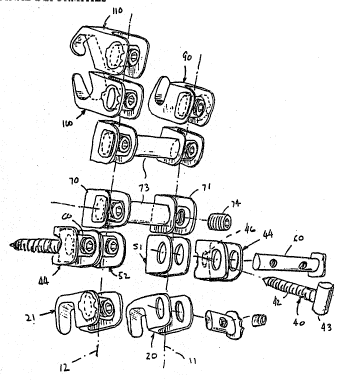
Fig. 2 is an exploded perspective view of the
construct of figure 1, showing the various elements
or components that make up the construct;
Fig. 3 is an enlargad, fragmentary, perspective,
exploded view of one of the hooks of figure 1
showing the hook bar and set screw use!d therewith in
position to rPceive the elongate distraction or
compression rod;
Fig. ~ is a view similar to figure 3, showing the
rod in place in the hook body, and the hook bar about ~
to be inserted; .
~ ig. 5 is a view similar to figure 4/ showing the
rodl hook bar and set screw all in operative position
to secure the hook to the rod;
Fig. 6 is an exploded view in side elevation o~ a
bone screw coupler and bone screw as used in the. :
invention;
Fig. 7 is a distal end view in elevation of the
bone screw coupler of figure 6;
Fig. 8 is a distal end view in elevation of the
bone screw used in the apparatus of figure 6;
Fig. 9 is a top plan view of a bone screw ~
coupler, bone screw, cross bar and set æcrew as used ~ .
in the apparatus of ~igure 6;
Fig. 10 is a somewhat schematic view, in
transverse cross section, of a vertebra having a pair
of convergent bone screws and a cross bar attached
thereto, producing a delta configuration and
achieving a mechanical lock in accordance with one
aspect of the invention;
', "
.
,. ''
: , " . '
-, . . .:
2~72~
WO91/19469 PCT/US91/045B5
-13-
Fig. 11 is a view in side elevation of a pair of
mated hooks, wherein each hook has a different
configuration to enable cus~omization or optimizing
of the purchase of the hooks on differently shaped
lamina;
Fig. 12 is a side view, with portions in section,
of a hook and associated hook holder ~Eor use in
placing the hooks used in the invention;
Fig. 13 is an enlarged, fragmentaly view, with
portions broken away, taken along linea 13-13 in
figure 12;
Fig. 14 is an exploded perspective view, with
portions broken away, of a bone screw coupler, bone
screw and threaded driver for inserting the bone
screw in accordance with the invention;
Fig. 15 is a perspective view of a trial hook
tool for templating the lamina of the vertebra prior
to application of an appropriate hook;
Fig. 16 is a somewhat schematic dorsal view of
one form of the instrumentation of the invention
shown attached to a spine; and
Fig. 17 is a slightly enlarged Yiew similar to
figure 16, showing a part of the instrumentation of
the invention as it is applied to one of the
vertebrae. ~ :
Detailed ~ n of the Preferred Embodiments
For purposes o~ illustration, a spinal
instrumentation system for a particular construct,
i.e., extending from the level of lumbar vertebra L-4
to the S-1 lamina o~ the sacrum~ will be illustrated
and described herein. However, it is to be
understood that the same principles would apply to
differently configured constructs, extending oYer
di~ferent portions of the ~pine~
. .:.:. .:~: ~, .: i::
WO91/19469 ~ P~T/~S91/04585`~
-14-
Referring more particularly to the drawings, one
version of a construct for instrumentlng the spine in
accordance with the invention is referenced generally
at lO. As seen best in figures l, 2 and 13, this
construct comprises first and second elongate rods ll
and 12 extending generally parallel to one another,
and adapted to extend on laterally opposite sides of
the spine in spanning relationship to the deformity.
The rods each have a smooth, rounded cephalad end 13
and a flanged or headed caudal end 14. Moreover, in
the particular construct shown, the rod 12 has a
greater length than the rod ll in order to
accommodate additional instrumentation, dascribed
hereinafter.
A first pair of downwardly ~acing hooks 20 and 2l
are mounted on the caudal ends of the rods, in
abutting relationship to the flanged ends l4. These
hooks are of a first con~iguration, referred to
hereinafter as neutral hooks, and have a spine 22
extending generally perpendicularly to the axi~ o~
the respective rod; a downturned lip or hook 23 on
the anterior end of the spine; a rear wall 24 ~.
extending from the posterior end of the spine in
spaced, parallel relationship to the hook 23; and a
pair of spaced apart parallel walls or flanges 25 and :
26 projecting rearwardly from the wall 24. The walls
or ~langes 25 and 26 are spaced so as to closely
engage on opposite side~ o the respective rods, and
the hooks are secured on the rods by a ~ook bar 27
extended through aligned openings 28 and 29 in the
walls 25 and 26, on the posterior side of the : .
re~pective rod, and fastened in place by a set screw
30 extended transversely through a threaded opening : :
3l in the hook bar into contact with the respective
rod. In the particular ins~rumentation shown, these
hooks are engaged on the lamina of the sacrum.
':
'.,'
2~g~727
WO91/1~469 PCT/US91/04585
-15-
It should be noted that the open.ings 28 and 29
are oval in shape, and the hook bars have a
corresponding oval cross sectio~ so that they will
fit the openings in only one orientation. Further,
the hook bars have a shaped ~langed end 32 to limit
insertion of the hook bars into their respective
openings, and to provide a tactile and visual
indication of the proper orientation of the hook ~ar
in the openings. That is, the threaded opening 31 in
the hook bars is threaded to receive the sek screw
from only one end of the threaded opening, and i.t is
therefore necessary that the appropriate end of the
threaded opening faces in a posterior direction for
receiving the set screw. `
A pair of bone screws 40 and 4l are attached to
the respective rods in spaced relationship to the
hooks 20 and 21, for insertion into the pedicle of
the S-l vertebra in the particular construct shown.
The bone screws each comprise an elongate threaded
shank 42, having a T-shaped head 43 on the posterior
end (figures 6-9) and are carried by screw couplers
44.
The screw couplers 44 are generally U-shaped in
top plan view, and each comprises an anterior wall 45
having a central opening 46 therethrough for
receiving the shank 42 of the respective bone screws,
and a pair of spaced apart, parallel side walls 47
and 48 extending in a posterior direction from the ,.; .
wall 45. Aligned, oval shaped openings 49 and 50 are
formed through the side walls in spaced relationship
to the wall 45.
The head 43 of the bone screws is sized and
shap~d to fit snugly between the side walls 47 and
48, against the anterior wall 45, and just anteriorly
of the openings 49 and 50.
WO91/19469 ~ 7; 7 PCT/US91/0458
-16-
Second U-shaped couplars 51 and 52, constructed
substantially identically to the screw couplers 44,
are disposed in side-by-side, contiguous relationship
to the screw couplers and each has an anterior wall
53 with a pair of spaced apart parallel side walls 54
and 55 projecting rearwardly therefr~m. Aligned,
oval-shaped openings 56 and 57 are formed through the
side walls 54 and 55. These openings are also in
alignment with the corresponding openings in the
screw couplers when the two couplers are disposed
side-by-side as shown in the drawings.
The coupler pairs 44, 51 and 44, 52 are held in
mating relationship to one another an in secured
relationship on the rods 11 and 12, as shown in
figure 1, by cross bars 60 extended through the
aligned openings in the respective couplers. The
cross bars have a length sufficient to extend through
the openings in both couplers of the respective.
pairs, and each has a first opening 61 located to be
positioned midway between the side walls of the bone
screw coupler 44, and a second opening 62 located to
be positioned midway between the side walls of the
mating coupler 51 Qr 52. A set screw 63 is threaded
through the respective first openings and into
engagement with the head 43 of the bone screws, and a -
set screw 64 is threaded through the respective
second openings and into engagement with the rods 11
and 12, securing the screws to the screw couplers,
securing the coupler pairs together, and securing the
entire assembly to the rods.
~S~L7~
WO91/19469 PCT/US91/04585
-17-
As indicated in figure 9, the screw can pivot or
tilt about the longitudinal axis or the T-shaped head
43 in the screw coupler, which axis, as seen in
figure l, is generally parallel to the axis oP the
rod ll or 12 to which the screw is attached. This
enables the bone screws 40 and 41 to be screwed into
the pedicle of the vertebra or body of the sacrum
such that the screws converge toward one another, and
in conjunction with the cross bar form a delta
configuration. Thus, the screws grip a wedge-shaped
section of bone between them, defining a mechanical
lock and affording a much stronger purchase on the
bone than could be obtained by the screw threads
alone.
A first rod coupler 70 extends between the rods
ll and 12 just above the level o~ attachment of the
bone screws, and is secured to the respective rods at
its opposite ends by use of couplers 71 and 72,
constructed identically to the couplers 51 and 52
used in association with the bone screw couplers. A ,:
cross bar 73 o~ appropriate length for the anatomy of
the patient being instrumented extends between the
couplers 71 and 72 and is secured in position on the
rods ll and 12 by set screws 74 and 75, respectively.
A second rod coupler 80 xtends between the rods
ll and 12 in spaced relationship above the first rod
coupler, and is constructed identically to the first
rod coupler. Accordingly, further description of
this rod coupler will not be given. It is su~icient
to note that the two rod couplers form a
quadrilateral construct with the rods ll and 12,
maintaining the rods in appropriately spaced
relationship on laterally opposite sides o~ the
spin~. This ~uadrilateral construct de~ines a
"ladder" con~igurationl stabilizing the rods ll and
12 botb torsionally and in the ~rontal plane.
-,'.
~ .
., . : ~: ., . . ,, : ~ :. : . . : . .. :.
WO9l/19469 ~ 7 2 ~ PCT/US91/0458' -
18-
Moreover, the cross bars function conjointly with the
convexgent bone screws to form the mechanically
locked delta configuration described previously, and
eliminates the need for distraction to achieve
fixation.
A third neutral hook 90, identica.l in
construction to the hooks 20 and 21 p:reviously
described, i5 secured on the rod 11 i~mediately a~ove : .
the second rod coupler 80. This third neutral hook
is oriented with its hook opening upwardly or toward
the head o~ the patient, and in the construct shown
is intended to engage on the caudal side of the right
lamina of the L-4 lumhar vertebra, as viewed from t:he
dorsal side of the spine. As in the previous .~
examples, this hook is secured to the rod by use o~ .
the hook bar 27 and set screw 30. :.
Second and third hook configurations lO0 and llO, .. ;;
respectivelyj are secured on the cephalad end of the
rod 12 immediately above the second rod coupler 80,
~or gripping engagement on both th~ cephalad and
caudal surfaces of the le~t lamina of the L-4 lumbar .:~
vertebra. This engagement both above and below the
lamina of this verte~ra maintains the instrumentation
in proper engagement wi~h ~he spine during bending
movements of the patient.
: The second hook configuration 100 is a down-angle
or downwardly opening hook and has a curved anterior
wall lO1 and a pair of spaced part, parallel side
walls 102 and 103, with aligned openings 104 and 105
therethrough just as in the previously described
hooks 20, 21 and 30. However, in this configuration
the hook opening is defined by a hook or lip 106 that
is inclined in an anterior direction at about a 45
: angle, and a complementally shapsd posterior wall 107 ~. `
; that extends parallel to the lip 106 in spaced
: . relationship thereto. .
. ~ ....
. . ..
,
. .:.
.,
2~72~
WO91/19469 PCT/US91/04585
--19--
Third hook configuration 110 is an up~angle or
upwardly opening hook that also ha~ a curved anterior
wall 111 and a pair of spaced apart, parallel side
walls 112 and 113, with alignsd openings 114 and 115
therethrough just as in the previously described
hooks. However, in this configuration the hook
opening is defined by a hook or lip 116 that includes
a first section 117 extending downwardly in an
anterior diraction at about a 45O angle, and
terminating in a second section or tip 118 that
extends downwardly in a posterior direction
perpendicular to the first section. A complementally
shaped posterior wall 119 extends parallel to the tip
118 in spaced relationship thereto, and as seen in
figure lO has a considerable length.
All of the hooks and couplers have essentially
U-shaped bodies open toward the posterior side,
whereby when the hook bars and/or cross bars are
removed, the rods can simply be laid into the hoo~s
and couplers from the posterior side thereofu
Moreover, the hook and coupler bodies, particularly
the curved anterior wall, spaced side walls and oval
shaped openings, are all virtually identical. This
enables the hooks and couplers to be mated and
organized on the rods in any order, right side-up or
inverted, and in any combination.
Further, the various couplers and hooks are able
to rotate on the rods 11 and 12, even when the set
screw is partially tightened to prevent axial
transIation of the hooks and/or couplers along the
rod. By loosening the set screws ~ the hooks and/or
couplers may be easily moved axially along the rods. ~ -
Thi enables the surgeon to quickly and easily adapt
the instrumentation to the di~ferent anatomies of
dif~erent patients. This ability of the rods to
rotate in the hooks and/or couplers has the
additional advantage of enablinq the instrumentation
to be used to derotate a scoliotic curve.
... . ... ...... . ... .. . . . - . - ~ . . .. . .
WO91/19469 ~ P~/US91/0458S`
-20-
Additionally, and as noted earlier herein, the
cross bars are provided in a multiplicity of lengths,
varying by one-half diameter of the set screw fxom
one size to the next. This enables the surgeon to
vary closely match the width of the finished
construct to the anatomy of a particular patient, and
eliminates the stress which would othe~ise be
imposed on the components by a too-wide or too-narrow
construct for the anatomy of the particular patient.
In order to facilitate handling and placement of
the hooks, a unique hook holder 120 is provided
(figures 12 and 13). This tool is a scissor- or ..
forceps-like device, and comprises a pair of opposed
jaws 121 and 122 having a shaped projection 123 on
khe confronting faces for mating engagement in the
aligned openings in the various hooks, shown here as ~;
a neutral hook 20. The jaws are manipulated toward
and away from one another by elongate handles 124 and ..
125, operating through a pivot 126. A pivoted
latching bar 127 is carried on the distal end of ons
of the handles 125, and has a serrated undersurface
128 which cooperates with a tooth 129 on the distal -
end of the other handle 124 to latch the handles and
thus the jaws in any of a plurality of positions, and
securing the grip of the.tool on the hook until
released by the surgeon or an assistant.
Insertion of the bone screws 40, 41, etc., is
accomplished by use of a special threaded driver
140. This tool resembles a screwdriver, with a . .:
handle 141 and elongate shank 142 extending axially .
therefrom. However, rather than a screwdriver blade
; on the end of the shank, the distal end of the shank
is externally threaded at 143. This threaded end is
matPd with the threaded opening 31 in the hook bar . :
27, whereby the threaded end of the driver may be
engaged in the threaded opening of the hook bar to
securely engage the driver with the bone
~a~7~7
WO91/19469 PCT/US91tO458S
-21-
screw/coupler/hook bar construct. The tool may then
be manipulated similarly to a scxewdriver to rotate
the screw and its coupler until the screw is inserted
into the pedicle of the vertebra. The driver is then
disengaged from the opening 31 to enable the bone
screw and its coupler to be attached to the rest of
the instrumentation.
Trial hooks are used to template the lamina of
the vertebrae prior to selection and use of an
appropriate hook 20, 100 or 110. These trial hooks
are in the form of a tool 150 tfigure 15), and
comprise one each of the different hook
configurations, with two different sizes for each
configuration. The ~ool 150 shown in figure 15 is a
trial hook for the neutral hook configuration 20, and
rather than the spaced, parallel side walls 25 and 26
provided on the hook used in the final construc~, has
a solid body with a permanently attached handle lS1.
In use, an approximately sized trial hook is selected
by the surgeon, based on his observation of the
lamina to be templated r and the trial hook is seated
on the lamina using a mallet and driver (not shown).
The trial hook sh~uld fit snugly on the lamina, and
each of the three surfaces of the hook opening should
contact a corresponding surface of the lamina. When
an appropriately sized and configured trial hook has
been found, a correspondingly sized and configured
hook for use in the final construct is selected by
matching it to the trial hook.
Instrumentation of the Spine
Usinq the System of the Invention
The surgeon should approach the spine in his
usual and customary method, exposing the spinous
pr~cessus, lamina, facets and transverse processus of
the involved spinal segments, after which the spine
may be instrumented with the system o~ the invention.
` , ' ~''';.
'
.: . , " . ~ . - . . . . , , ~
, ~ : . . . .. . .
: , :, : . . . ,,, - . .:
WO91/19469 ~ 7 2 7 PCT/~s91/0458s
-22-
The system of the invention offers screws that
are cannulated, and at the surgeon's preferen~e, can
be inserted with the aid of fluoroscopy or by
exposure of the pedicle. The following description
will be for the pedicle exposure methcld.
After exposing the pedicle and choosing the
appropriate point of entry into the pedicle, the
cortex is broached with a pedicle probe (not shown).
The first five millimeters o~ the pedicle are entered
with this probe, followed by hand drilling of the
pedicle in a slow, circular motion to an appropriate
depth, and then driven into the body o~ the vertebra
to an appropriate depth. The position and depth
should be confirmed radiologically and once the
appropriate depth has been obtained, a depth gauge
(not shown~ is used to determine the screw length.
The appropriate length screw is then chosen in
preparation ~or insertion.
The appropriate length screw is placed in the
screw coupler 44, a hook bar 27 is inserted through
the aligned openings in the coupler, and the threaded
driver is engaged with the threaded opening 31 in the
hook bar. An open end wrench ~not shown) is used to
hold the screw/coupler construct while the driver is ,
being tightened in the opening 31 in the cross bar.
The screws 42 are self tapping. However, a pilot
hole may be pre-tapped in the pedicle with an
appropriate mated tap (not shown), i~ desired. The
ped.icle tap depth may be measured with a suitable
guide (not shown) such as used for guiding the depth
of insertion of the drill bit during the drilling
procedure.
:, .
~ . ~ . . . .... ..
2~72~
WO~1/19469 PCT/US91/04585
-23-
The construct for~ed by the driver 140, screw 40,
screw coupler 44 and hook bar 27 is manipulated with
the driver to screw the construct into the pedicle to
fully engage all of the threads on the shank 42 of
the bone screw. The driver is then removed from the
threaded opening 31 in the hook bar, while the
construct is stabilized with a wrench. The hook bar
27 is also then removed from the coupler 44. This
procedure is repeated on the contralateral side. The
~urgeon then repeats these steps for the number of
levels to be instrumented with screws.
Prior to templating the lamina with the trial
hooks 150, each lamina should be made square with a
small laminotomy at its inferior lateral corners.
The ligamentum flavum should be elevated o~f the ;-
lamina in a subperiosteal manner to allow proper ~ -
seating of the hook.
When instrumenting the ~pine from the thoracic to
L-5 lumbar lamina, the most cephalad and caudal
lamina must be captured unilaterally with
appropriately mated hooks. When the spine is
instrumented with the inclusion of the sacrum, the ~ ' -
sacral segment is instrumented with bilateral laminar
hooks and bilateral bone screws inserted into the S-l
pedicle.
The instrumentation shown in the present instance
is from the sacrum to the L-4 lumbar vertebra. The
instrumentation is most easily started at the sacrum
by templating the S-1 lamina with an appropriate
trial hook. NPxt, the most proximally instrumented
lamina is templated, in this case the L-4 lamina.
The lamina of L-4 is exposed unilaterally at its
most cephalad edge and a small laminotomy is used to
s~uare o~f the lateral-mo~t border of the lamina.
After the ligamentum fla~um has been freed, the
appropriate trial hook is selected. This is usually
the up-angled hook configuration 110. Once the
WO91/19469 2 0 ~ ~ 7 2 ~ PCT/US91/04S85
-24-
laminar hook is found to be well seated, the caudal
edge of the L-4 lamina is exposed in a similar
manner, this being done bilaterally. Appropriate
hooks are applied to either side of the midline. In
this construct, the down-angled hook configuration
100 is chosen.
At this point, the surgeon has determined the
proper hook size and configuration for use in the
construct.
The length of the rods 11 and 12 to be used is
determined by utilization of a flexible rod template
(not shown). Rods of appropriate length are selected ;
from pre-cut rods or they are cut to size. After an
appropriate length rod is selected, a lordotic curve
may be applied in a conventional manner, i~ needed.
The previously chosen sacral hook 21, hook bar 27 -
and set screw 30 are assembled on a rod 12, with the
hook engaged against the caudal end 14 of the rod.
The set screw is partially tightened so that the
sacral hook 21 can be rotated on the rod but not
moved axially on the rod. Next, a coupler 72 and an
appropriate length cross bar 73 are mounted on the
rod and allowed to abut the previously mounted sacral
hook 20. The set screw of the coupler is then
tightened suf~iciently to prevent axial movement of
the coupler on the rod but yet enabling the sacral to
be rotated about the axis of the rod.
The lamina of L-4 is approached and tricortical
capturing of the lamina is per~ormed unilaterally
with the previously chosen hooks 100 and llO. These
are seated onto the lamina and held in position by
use of the hook holders 120. The inferior and
superior hooks of the same lamina are held ~`
simultaneou~ly, while the rod, coupler and sacral
hook construct is mounted onto the lamina of 5-1.
The rods o~ this construct are then laid into the
open slots of the hooks 100 and 110, which have been
previously seated on the L-4 lamina.
:
~ v ~
WO91~194~9 PCT/US91/~4585
-25-
Each hook holder i5 sequentially removed after a
hook bar and set screw have been applied to the hooks
l00 and ll0 to maintain them in position. This step
is repeated for each laminar hook.
Once the construct is formed, the lordotic curve
of the rod is rotated appropriately in the sagittal
plane and all set screws are tightened but not
torqued.
The process is repeated for the contralateral
side, keeping in mind that the L-4 lamina is captured
unilaterally. In this case an up-angled hook ll0 has
previously been applied to the opposite side.
Distractors, not shown, can be used at this point
to maintain appropriate tension between the
inferiorly down-angled hook l00 o~ L-4, and the
neutral hook 21 o~ the sacrum. It must be reme~bered
that the system does not rely on distraction for its
stability, and that only enou~h distraction should be
applied to hold the construct in position.
The set screw is removed from the cross bar 73 of
the previously mounted coupler 72, and an appropriate
length cross bar 73 is used to connect the mated
couplers 71 and 72 on the rods ll and 12. If the
previously mounted cross bar 73 is of inappropriate
length, it may be replaced at this time. This
maneuver is performed to include as many transverse
cross bars as needed. In the present construct, only
two are needed to c~mplete the quadrilateral frame.
The sacral hooks 20 and 21 will now have oriented
themselves to the slope of the sacral l~mina in the
transverse plane, and their set screws may be
tightened, but not torqued.
The most proximal coupler 7l, 72 and transverse
cross bar 73 construct is slid pro~imally on the rods
to allow the application of couplexs 51, 52 that will
be mated to the previously installed bone screw
coupIers 44~ and secured by cross bars 60 and set
screws.
" . . .... , . - ........ , . . ... . . ,. ~ , . . .
' : , ''" ' : ' ', ,.' '., . . . ' , . ' ": ' '. . ' " ," . .~ ` ' ' , . ' ' ' ' ' ' ' ' ~ . ' ' :
WO91/19469 ~ 26- PCT/US91/045B'
The construct is now complete and if no changes
are necessary, each set scr~w is torqued with a
torque wrench while an assistant stabilizes the
construct with a rod holder (not shown). The torque
wrench ensures that an appropriate amount of torque ~,
is applied without over-torquing the system or
stripping the set screws. Use of the torquP wrench
to torque the set screws at each of the attachme~ts
produces a constant holding force throughout the
construct.
The modularity of the system affords the surgeon
great flexibility in configuring the internal
fixation to the anatomic constraints without
compromising fixation capabilities. It also allows -
customization of the hook and screw fixation and does
not limit or commit the surgeon to either fixation
mode. Further, components can be added after a ;
construct has been completed. This gives the surgeon
the ability to instrument any additional segments at ,~
a later setting without having to dismantle the
existing construct. ~;
The ability o~ the couplers and hooks to pivot on
the rods ~akes it possible to use the construct to ~ ;
derotate a scoliotic curve, thus providing additional
correction capabilities. This derotation can be
performed with a hook construct, a bone screw
construct, or a hybrid construct including a
combination of hooks and bone screws.
~ The slotted or open back hook and coupler design
facilitates instrumentation by allowing the hooks to
be preseated onto the lamina, followed by application
of the rods into the slots of th2 hooks and couplers,
rather than having to pre mount the hooks onto the
rods. The same aase o~ instrumentation i5 also
provided by the screws, which are affixed to the bone
prior to the application of the rod(s). The locking
mechanism, i.e., the set screws and bars, are easily
accessible from a dorsal approach, adding further to
the ease of use of the system.
:
''
:
~ . . . : .~ . - : '
WO91/1~469 PCT/USg~/04585
27-
The unique, multiple hook configurations permit
tricortical capturing of the lamina and avoids the
single point laminar contact that is sometimes
obtained with prior art systems. The superior fit of
the hooks onto the lamina also minimizes intrusion
into the spinal canal, and the angled hook
configura~ions of hooks 100 and 110 compensates for
the "shingling" of the vertebrae in the spine. This
also makes it possible for the surgeon to instrument
the system without having to contour a lordotic curve
into the rod.
-The use of screws in the sacral pedicle permits
fixation of the system to include the sacrum, and the
use of the transverse cross bars not only forms a
quadrilateral construct but also cooperates with the
convergent bone screws to form a delta configuration,
obtaining purchase on the bone by gripping a wedge
shaped section o~ bone and forming a mechanical
lock. This provides a much more secure purchase than
relying solely upon engagement of the threads of the
screws in the bone.
Further, the ability of the heads of the screws
to pivot in the screw couplers permits the surgeon to
place the screws in such a manner that they need not
be at the same level from the laminar margin, and at
the same time allows coupling of the screw to the
coupler via the transverse cross bars. The ability
o~ the screw coupler, screws, and couplers to rotate
further enables the screws to be inserted in optimal
position relative to the pedicle ~or maximum
purchase, and minimizes pedicle cut-out. This same
flexibility also permits the bone screws to be
coupled to the rod with the use of various length
transverse cross bars, thereby avoiding preloading of
the bone screws.
,
WO91t19469 PCT/US~1/0458~
-28- ..
,
The system of the invention remains medialized ,
and is of low profile, allowing the spinal surgeon to
perform his decortication and application of the bone
~raft as a last step in the fusion. This reduces
intraoperative bleeding and morbidity associated with
the surgery by not having to work in a bloody f~eld.
Although the invention has been described wlth
reference to a particular embodiment, it is to be
understood that this embodiment is merely
illustrative of the application of the principles of ::
the invention. Numerous construct configurations may
be made therein and other arrangements may be devised
without departing from the spirit and scope of the
invention. :~
.
'
':
. ~ ' '
: