Note: Descriptions are shown in the official language in which they were submitted.
2~1~5~2~
PLASMA ARC TORCH WITH IMPROVED
NOZZLE SHIELD AND STEP FLOW
Backqround of the Invention
This invention relates to plasma arc cutting
torches. More specifically, it relates to a plasma
arc cutting torch and method that protect the nozzle
from gouging and double arcing during the piercing and
cutting of metal workpieces.
Basic components of modern plasma arc torches
include a torch body, an electrode (cathode) mounted
within the body, a nozzle (anode) with a central
orifice that produces a pilot arc to the electrode to
initiate a plasma arc in a flow of a suitable gas,
typically nitrogen, and associated electrical
connections, passages for cooling, and arc control
fluids, and typically a ceramic insert mounted at the
face of the torch immediately adjacent the workpiece
Various plasma arc torches are known which
control the flow dynamics of the fluids producing the
plasma. One of the present applicants, for example,
is the patentee of U.S. Patent No. 3,641,308 which
uses a flow of a cooling water developed in the nozzle
of the torch to constrict the plasma arc to produce a
better quality cut. Any torch must also provide
cooling since the plasma arc produces temperatures in
excess of 10,000C which, if not controlled, could
destroy the nozzle. Water cooling has heretofore been
~L
2~6~025
preferred because the heat transfer ability of water
is much greatee than that of any gas, and water is a
readily available, inexpensive liquid. In piercing
metal, however, another important design consideration
is the ejection of molten metal from the cut kerf back
onto the torch which can destroy the nozzle. There
are two principal modes for this destruction. First,
molten metal ejected from the cut kerf can disturb the
plasma jet causing it to gouge the nozzle. Second,
the molten metal can solidify and adhere to the front
face of the nozzle which eventually causes an
electrical bridging between the nozzle and the
workpiece. This results in "double arcing" which can
drastically reduce the life of a nozzle.
There have been several approaches to solving
the gouging and double arcing problems created by the
ejection of molten metal. In high current plasma
cutting torches (200 amperes and more), the solution
has been to use a multi-piece nozzle with water
injection cooling. A typical such nozzle of the type
manufactured by Hypertherm, Inc. is illustrated in a
simplified schematic form in Figs. la and lb. In Fig.
la, corresponding to Hypertherm Models HT400 o.099,
HT400 0.166 and PACS00 0.187, the front face of the
nozzle is made of a ceramic. This arrangement
controls gouging and double arcing because (1) the
ceramic nozzle face is non-conducting and therefore
will not cause double arcing and (2) the nozzle is
protected by the ceramic barrier. Further the
excellent cooling properties of the water, operating
20650~
by cooling the ceramic nozzle piece and by water vapor
cooling the molten metal ejected during piercing,
inhibit the molten metal from boding or fusing to the
ceramic element or in the extreme case, from attacking
the ceramic. Figure lb shows a variation on the
high-current, multi-component nozzle similar to the
nozzle sold by Hypertherm as its Model PACS00 0.250.
Again, the key to the solution is radial water
injection, but the ceramic nozzle piece is replaced by
a copper front piece. An insulating element separates
the nozzle components so that the front of the nozzle
is floating electrically. The copper is more readily
cooled than the ceramic and it withstands abuse
significantly better, and therefore has a longer life.
At low current operation, 0-200 amperes,
water injection ~ecomes less practical. Aside from
the obvious additional costs of the water cooling
system and fabricating a multi-part nozzle, at these
lower power levels water cooling draws too much energy
from the plasma. However, the problem of high nozzle
wear due to piercing remains. Heretofore the only
commercially viable solution known to applicants has
been to use a single piece copper nozzle, take no
measures to protect it against splattered molten
metal, and to restrict operation to currents below 150
amperes. The nozzle is sometimes gas cooled, and the
gas can serve as a cover gas, but there is no piercing
protection for the nozzle. Molten metal can, and
does, deflect the plasma arc so that it gouges the
nozzle and can, and does, build up on the nozzle face
-
~4~ 2065~25
causing double arcing. Because this nozzle is
comparatively inexpensive to fabricate, industry
practice is to accept nozzle destruction and to
replace the nozzle periodically. A typical life for a
nozzle of this type, operating at 40-50 amperes, is
about 1 hour of operation when used to pierce 1/4 inch
mild steel.
Fig. 2a shows, in simplified schematic form,
a typical one-piece, low-current nozzle of this type.
As shown, a cooling gas flow is typically along the
outer surface of the nozzle toward the workpiece.
Nozzles of this type are sold by Hypertherm, Inc. as
its Model Nos. HT40 0.038 and MAX100 0.059. There
have been attempts to protect low-current,
single-piece nozzles. One attempt is shown in Fig.
2b. A ceramic insulating sleeve is attached to the
outside of the nozzle. This is a so-called "shield
cup". Its main purpose is to stop nozzle-to-workpiece
contact. An operator can then touch or drag the torch
on the workpiece without double arcing. This ceramic
sleeve, however, offers no protection during piercing
against molten metal splatter and the attendant
gouging and double arcing problems. Also, the ceramic
shield (1) is brittle and breaks easily and (2) not
having the protection of w2ter cooling, is attacked by
the molten metal e~ected from the cut.
In all of the prior art designs shown in
Figs. la - 2b, there is no arrangement to control
interference of the cooling fluid with the cut. There
is also no arrangement disclosed which provides extra
2116502S
protection for the nozzle during an initial piercing
of the metal, as compared to normal cutting conditions
once the metal is pierced.
While replacement of one-piece nozzles may be
acceptable the 0-50 ampere range, at the 50-200 ampere
range the molten metal damage to the nozzle occurs so
guickly that nozzle replace~ent is economically
undesirable. The problem is worse with increased
currents, so that, commercial plasma arc cutting
torches using single piece nozzles are not yet
available to operate above 150 amperes.
It is therefore a principal object of this
invention to provide a plasma arc cutting torch and
method that protects the torch nozzle from gouging and
double arcing, without using water cooling while
operating at current levels from 0-200 amperes, or
even higher, and which provides extra protection for
the nozzle on piercing.
Another object of this invention is to
provide a plasma arc torch and method with the
foregoing advantages that uses gas cooling, but where
the gas exiting the nozzle during cutting does not
interfere with the cutting action of the arc or
degrade the quality of the cut.
A further object of the present invention is
to provide the foregoing advantages with a single
piece nozzle.
Another object of the present invention is to
provide the foregoing advantages using replaceable
components and standard materials that can be adapted
-6- 2~ 6 5 025
to retrofit existing plasma arc torches which have no
piercing protection.
Yet another object of the invention is to
provide the foregoing advantages while maintaining a
favorable cost of manufacture.
Summary of the Invention
A plasma arc cutting torch has a body, an
electrode mounted within the body, and a nozzle
mounted on the body at a lower end of the torch
adjacent a workpiece to be cut. A space between the
electrode and the nozzle defines part of a primary gas
flow path for gas that is ionized to produce a plasma
arc. The body has internal passages to supply the
primary gas, and the nozzle has an outlet orifice from
which the plasma arc exits the torch once the arc
transfers to the workpiece for piercing. The torch
also includes conductors which introduce a direct
current, typically in the range of 0-200 amperes, to
the electrode-nozzle pair.
A cup-like shield formed of a material with a
large thermal conductivity, preferably copper, is
mounted on the lower end of the torch to substantially
enclose the nozzle, in a spaced relationship, except
for (i) a central exit orifice that is generally
aligned with the nozzle orifice and (ii) at least one
and preferably plural bleed holes equiangularly spaced
around the exit orifice and lying in the front face of
the shield immediately opposite the workpiece A
mounting ring formed of a dielectric material supports
--7--
2a65û25
the shield and insulates it electrically from the body
so that the shield is electrically "floating". A
secondary gas flow path through the torch body directs
a flow of cooling gas to the space between the nozzle
and the shield. Preferably the secondary flow first
enters a plenum formed in the body by a cap threaded
onto the body which in turn supports the dielectric
mounting ring. The plenum feeds the cooling gas
through a set of canted ports formed in a flange of
the cap swirl the secondary gas flow. A portion of
the swirling flow exits the torch via the bleed holes
formed in the front face of the shield. The remaining
gas flow is directed to and stabilizes the plasma
arc. The flow cools the front face of the shield.
The number and dimensions of the bleed holes, the exit
orifice diameter, the shield-nozzle spacing and the
secondary gas flow rate are correlated empirically for
each application to produce the aforementioned
stabilization and a sufficient cooling of the shield
to resist the adherence or fusion of molten metal on
the shield. The upper edge of the shield at the exit
orifice is preferably rounded to facilitate the smooth
merging and exit from the torch of the remaining
cooling gas flow and the plasma arc (the ionized
primary gas flow).
The bleed ports are angled away from the
plasma arc at an angle of 5 to 90 from the vertical
(the direction of the arc, transverse to the metal
workpiece). The angle is preferably about 55 and
formed by a straight cylindrical bore in an angled
-8- 2~65~2~
side wall of the nozzle shield. The degree of
angling, whether of the bore, the side wall, or some
combination of both, is correlated with the particular
application to ensure that the excess secondary
cooling gas existing through the bleed ports does not
interfere with the action of the arc in making the
cut.
The secondary gas flow line includes a
mechanism to change the flow rate of the secondary
cooling gas quickly and reliably in order to adjust to
changes in the operating conditions of the torch. In
a preferred form, an electrically actuated valve in
one parallel branch in the flow line allows a heavy
flow when the valve is open. This condition provides
a substantial cooling of the nozzle sufficient to
protect the nozzle even under the extremely hostile
conditions experienced on piercing a metal workpiece.
After piercing, this valve closes and the secondary
gas flows through a second ~arallel branch containing
another valve that is set to allow a much smaller
flow, suitable for normal c~ltting of the workpiece
without the cooling gas deg-ading the cut quality.
With this structure, a gas flow has been
found to be sufficient to cool the shield sufficiently
to prevent its destruction ~y the molten metal or the
plasma itself despite the fact that the specific heat
of the gas is many times smaller than that of cooling
liquids, especially water. The flow has also been
found to significantly improve the quality of the cut
made by the torch. The bleed ports and exit orifice
.
- 2065025
g
are relatively small openings so that the shield
blocks substantially all of the molten metal that
would otherwise quickly destroy the nozzle. Locating
the bleed ports in the side wall of the nozzle shield
rather than its front face opposite the workpiece also
aids in shielding the nozzle from splattered molten
metal.
Stated as a process the present invention
involves the steps of blocking the molten metal
ejected from the cut-from reaching the nozzle using a
shield, cooling the shield with a secondary gas flow,
and controlling the secondary gas flow rate as a
function of the operations performed by the torch.
The process also includes bleeding off a portion of
the flow to enhance the total flow rate, swirling the
flow at a sufficient velocity and mass flow rate to
provide a cut of good quality and directing the
bled-off flow away from the arc to avoid interfering
with the cut.
- These and other features and objects of the
present invention will be more fully understood from
the following detailed description which should be
read in light of the accompanying drawings.
Brief Description of the Drawings
Fig. la is a simplified view in vertical
cross section of a prior art electrode and multi-piece
nozzle of a high-current, water-injection plasma arc
torch;
Fig. lb is a view corresponding to Fig. la of
2065025
--10--
an alternative prior art multi-piece, water-injection
nozzle;
Fig. 2a is a simplified view in vertical
section of a prior art one-piece, nozzle and electrode
of a plasma arc torch for use with low currents;
Fig. 2b is a view corresponding to Fig. 2a of
an alternative prior art one-piece nozzle embodiment
for low current use using a cylindrical ceramic shield;
Fig. 3a is a simplified view in cross section
of a plasma arc cutting torch according to the present
invention;
Fig. 3b is a detailed view of the nozzle,
cap, shield and gas flow paths of the plasma arc torch
shown in Fig. 3a;
Fig. 4 is a view in perspective, with
portions broken away, of the lower portion of the
plasma arc torch shown in Figs. 3a and 3b;
Fig. SA is an exploded perspective view of
the torch shown in Fig 4;
- Fig. 5B is a perspective view of the torch
shown in Figs. 4 and 5A;
Fig. 6 is a view in perspective corresponding
to Fig. 4, but showing an alternative shield
configuration;
Fig. 7 is a simplified view in side elevation
and partially in section showing the plasma arc torch
of Figs. 3a-6 piercing a workpiece;
Fig. 8 is a view in vertical section of the
cut kerf in the workpiece shown in Fig. 7 after
piercing; and
-11- 206~
Fig. 9 is a view in vertical section
corresponding to Fig. 3a showing a system for stepping
the secondary gas flow and for directing the bleed gas
away from the cut.
Detailed Description of the Preferred Embodiments
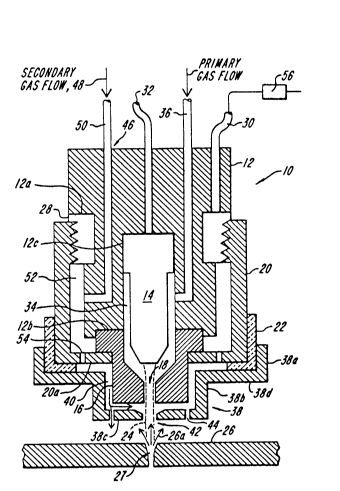
Figs. 3a and 3b show in simplified form a
plasma arc torch 10 constructed according to the
present invention. The torch 10 has a body 12, and
electrode 14, a nozzle 16 with a nozzle orifice 18, a
cap 20 threaded onto the body and an insulating ring
22 threaded or otherwise secured on the cap. As is
also shown in Figs. 7 and 8, a plasma arc 24 impinges
on a workpiece 26, e.g. a thick sheet of mild steel
where it pierces the metal creating a cut kerf 27.
Molten metal at the site of the piercing initially is
ejected laterally, but as the cut becomes deeper into
the workpiece, molten metal 26a is ejected more
vertically so that it is directed back towards the
nozzle 16. The ejection of molten metal from the
workpiece to the nozzle is most severe, and most
likely to damage the nozzle, during this initial
piercing. During normal cutting, the molten metal can
run out of the kerf under t~.e force of gravity.
Therefore, during cutting it becomes less critical to
cool the nozzle, but more critical to avoid
interference between the cooling gas exiting the
nozzle and the cutting action of the arc in the kerf.
As shown, the body 12 is a generally solid,
cylindrical single piece with various internal
-
-12-
2065û2~
passages and recesses to provide the necessary fluid
flow passages and electrical connections, whether
alone or in cooperation with other components.
However, the body can be formed of multiple pieces
with any of a wide variety of configurations provided
that they provide the necessary support functions and
form the necessary internal passages. In the
preferred form shown, a current ring 28 is secured to
the outer surface of the body 12 in a circumferential
recess 12a. The current ring is formed of a material
that has good electrical conductivity properties, such
as brass, and is in electrical connection with a pilot
arc lead 30 which passes through the upper end (as
shown) of the body 12. The cap 20 is also formed of a
good conductor, such as copper or brass, and closes a
pilot arc circuit to the nozzle 16 which is clamped in
place, replaceably, between a cap flange 20a and a
circular recess 12b formed on the lower end of the
body 12. The recess 12b and cap 20 also align the
nozzle radially within the torch. The body also has a
central bore 12c that holds the electrode 14
replaceably in electrical connection with a current
lead 32 that also passes through the upper end of the
body 12. The recess 12b also aligns the electrode so
that it is ~enerally uniformly spaced from the
interior surface of the nozzle to define therebetween
a plasma chamber 34. A gas tube 36 passes through the
body 12 to direct a primary flow of a conventional
gas, such as nitrogen, to the chamber where it is
ionized and forms plasma arc 24 exiting the nozzle
-13- 2~6~D25
orifice 18.
A nozzle shield 38 is threaded at its upper
side wall 38a to the insulating ring 22. In the
simplified form shown in Figs. 3a and 3b, the shield
has a stepped, cup-like configuration including a
lower, generally cylindrical side wall 38b, a front
face 38c, and a recessed front face 38d that spans and
connects the side walls 38a and 38b. The shield is
preferably machined as an integral component from a
metal with a high thermal conductivity. Copper is
preferred. The shield 38 is configured so that it is
spaced from the cap flange 20a and the nozzle to
define a gas flow passage 40. The front face 38c of
the shield has an exit orifice 42 aligned with the
nozzle orifice 18 to provide a clear exit path for the
plasma arc. It also includes a set of generally
equiangularly spaced holes 44 spaced radially from the
exit orifice.
A secondary gas flow path 46 directs a flow
48 of a cooling gas, such as nitrogen, from a supply
tube 50 passing through the body 12 to a plenum
chamber 52 (defined by the cap, the opposite outer
wall of the torch body, and the clamped portion of the
nozzle) and then through a set of ports 54 found in
the cap flange 20a to the space 40. The plenum
chamber 52 provides a local reservoir of gas that
isolates the flow through the space 40 from transient
fluctuations in the gas pressure or flow rate in the
supply tube 50. The ports 54 are preferably
equiangularly spaced and sized to produce a sufficient
2û65û2S
gas flow rate through the space 40 to cool the shield
38 to a degree that inhibits the adherence of ejected
molten metal. The ports are also angled
circumferentially to induce a swirling motion in the
gas flow 48 through the passage 40. This swirling has
been found to be significantly related to the guality
of the cut kerf produced in the workpiece by the
plasma arc. The degree of angling of these ports is
related to the gas flow rate. With known torches, and
for typical cutting operations, an angling of 1 to
5, and preferably 2, has been found to be preferable
The holes 44 bleed off a portion of the gas
flow 48 to allow an enhanced flow rate, and therefore
increased cooling. The remaining gas flow 48a which
swirls inwardly from the bleed holes 44 to the exit
orifice 42 (1) cools the front face 38c and (2)
stabilizes the plasma arc, that is, it assists in
controlling the location and diameter of the arc so
that it does not attack and gouge either the noz21e or
the shield. The upper edge of the exit orifice is
rounded to smooth the transition of the remaining gas
flow 48a as it encounters and interacts with the
plasma arc, and then flows downwardly out of the exit
orifice 42.
Figs. 4-6 illustrate a commercial form of the
torch 10 shown schematically in Figs. 3a and 3b, like
parts having the same reference numbers. In Fig. 4
the shield has a planar front face as shown in Figs.
3a and 3b. In Fig. 5 the shield has a front face with
radially directed recesses associated with each bleed
- 2065025
--15--
hole 44. This arrangement reduces the likelihood of
ejected molten metal attacking the nozzle by passing
through one of the holes, or blocking the hole. Fig.
6 shows the lower end of the torch of Fig. 4 when it
is assembled. The electrode, current leads and gas
passages are not shown.
Fig. 9 shows an alternative form of the torch
10 which is substantially the same as the torch shown
in Fig. 3a except that (1) the nozzle shield 38 is
designed with the outwardly directed bleed holes 44
formed in a side wall 38b that is inclined and (2) the
secondary gas flow line 50 is fed through a flow
control system 60.
The holes 44 are preferably drilled directly
through the side wall 38b and are at an angle A with
respect to the "vertical" which is greater than zero
degrees, but preferably is about 55. Herein
"vertical" is defined as the direction of longitudinal
axis of the torch which is generally aligned with the
arc and is transverse to the surface of the
workpiece. The precise angle selected depends on the
gas flow rate and the cutting conditions.
In general, the heavier the flow required to
cool the nozzle, the larger the angle will be. While
the holes 44' are shown as straight cylindrical bores
perpendicular to an inclined side wall, they can, of
course, also be drilled at an angle, either in the
side wall 38b', a vertical side wall 38b as shown in
Fig. 3a, or the front face 38c (shown in phantom in
Fig. 3b as holes 44"). The perpendicular bore in an
; -16- 2 065025
inclined wall has been found to be a somewhat superior
design in terms of directing a flow that is as laminar
as possible, while also effectively bleeding off a
desired portion of the flow and achieving the desired
cooling of the nozzle shield.
The flow control system 60 includes two
parallel branch conduits 62 and 64 both fed by a
common supply of the secondary gas and both feeding
the same secondary gas supply line 50. The branch 62
has an in-line electrically actuated valve 66 that
moves between a closed position and a fully open
position. In the open position, the valve 66 passes a
heavy gas flow to the line 50 which produces a large
degree of cooling of the nozzle shield to protect the
shield during piercing. For example, in piercing 3/4
inch mild steel while operating at 200 amperes, the
secondary gas flow 48 through the valve 66 and the
line 50 is typically 240 scfm. When the workpiece is
pierced and normal cutting begins, an electrical
signal S applied over lines 68 closes valve 66. The
secondary gas flow is then diverted exclusively
through branch 64 containing a manually adjustable,
in-line set valve 70. This valve is adjusted so that
when valve 66 is closed, it meters a comparatively
light secondary gas flow to the line 50 which is
sufficient to cool the nozzle, but which does not
interfere to any significant degree with the action of
the arc in the kerf 27. For the same example given
above, this lighter "cutting" gas flow is typically 4
scfm. Besides, the sharp step adjustment produced by
-17- 2~65Q2~
valving the gas flow between branch 62 and 64, or
branch 64 only, adjustment of valve 70 allows a fine
tuning of the light flow through branch 64 to ensure
the proper level of cooling and a good cut quality.
This step flow gas control also allows the
swirl ports 54 to be angled much more severely than
would otherwise be possible, typically canted at 10.
Without a step flow, the heavy gas flow required to
cool the nozzle shield on piercing required that the
swirl ports be comparatively straight. However, then
during a lighter flow associated with normal cutting,
these "straight" ports produce comparatively little
swirl, with a corresponding deterioration in the
quality of the cut.
In operation, the torch is positioned over
the workpiece 26 at a nozzle-to-workpiece standoff
that is typically in the range of 0.100 to 0.200
inch. The precise distance varies with the current
and other operating parameters, as is well known in
the industry. To initiate the arc, the current path
is in a pilot arc mode: current flows from the
current lead 32 through the electrode 14, the nozzle
16, the cap 20, and the current ring 28 to the pilot
arc lead 30. The current is in the range of 0-200
a~peres, but can exceed 200 amperes. The torch is
operated in this mode long enough to ionize the gap
between the nozzle and the workpiece. When this
ionization occurs, a pilot arc between the electrode
and the nozzle transfers from the nozzle to the
workpiece. A relay 56 is then opened on the pilot arc
-18- 2 ~6 ~2~
lead 30 so that the current path of the transferred
arc is then from the current lead 32, through the
electrode 14 and to the workpiece 26 via the plasma
arc 24.
During the arc ignition, there is a primary
gas flow 58 through the tube 36 and plasma chamber
34. The flow preferably is swirling. The secondary
gas flow 48 is also initiated. The ports 54 swirl the
flow 48 which then proceed through the passage 40,
with a portion of the flow being bled off through the
holes 44. The secondary gas flow in the passage 40
cools the nozzle and the shield; the remaining gas
flow 48a cools the front face 38c of the shield and
stabilizes the plasma arc.
As the plasma arc heats the workpiece, it
melts the metal and the molten metal 26a is ejected
out of the developing "crater" at relatively high
velocities as shown in Fig. 7. Initially the forming
crater is relatively shallow and the molten metal is
ejected wide of the shield 38. As the crater becomes
deeper, the molten metal is ejected in an increasingly
vertical trajectory. Because the shield has a high
thermal conductivity, it can be cooled by the gas flow
48 to a degree that the molten metal does not attack
the shield, and adherence is controlled. (While some
metal may adhere, when the torch cools after a cut,
tapping the shield will cause the metal to fall off.)
Since the shield is insulated, no double arcing can
occur as a result of a metal build up. In pierci~g
thick workpieces (e.g. in excess of 1/2 inch), it is
- - 20 502~
also desirable to translate the torch laterally during
the piercing to reduce the opportunity for molten
metal to be ejected directly vertically back into the
nozzle orifice.
On piercing, the valve 66 will be open to
preferentially direct the secondary gas flow to the
torch. When the piercing is complete, as sensed by a
change in the current being drawn by the torch in a
manner well known to those skilled in the art, the
valve 66 closes and the secondary cooling gas flow is
decreased in a step-wise manner to a level set by the
valve 70.
The precise gas flow rate and the dimensions
of the various passages, orifices, ports and holes
will vary in an interrelated manner and depending on
the operating parameters. For example, a larger
current will, in general, require a larger secondary
gas flow rate to cool the torch and stabilize the
arc. In particular, while the exit orifice should be
large enough not to interfere with the egress of the
plasma arc, it should also be sufficiently small that
the remaining gas flow 48a interacts with the arc to
provide the desired stabilization. Further, the
secondary gas flow rate and velocity that are optimal
for the piercing and cutting modes of operation vary
for each torch and with different operating conditions
to produce a degree of swirling which results in the
best possible cut. The precise values for a given
torch and application are determined empirically. By
way of illustration, but not of limitation, for a 100
2 2~65025
ampere torch with a nozzle orifice diameter of 0.059
inch, the exit orifice is preferably about 0.170 inch.
There has been described a plasma arc cutting
torch with an electrically neutral metallic nozzle
shield operating in conjunction with a secondary flow
of cooling gas that protects the nozzle from gouging
and double arcing due to molten metal ejected from the
cut kerf. The torch includes systems to ensure that
the cooling gas flow is large enough to protect the
nozzle during piercing, but is changed in a
step-fashion to a small enough value to avoid
interference with the cutting operation after the
piercing. These systems are readily retrofit onto
existing torches and have a favorable cost of
manufacture.
While this invention has been described with
respect to its preferred embodiments, it will be
understood that various modifications and alterations
will occur to those skilled in the art from the
foregoing detailed description and drawings. For
example, while the secondary gas flow is described as
having an independent supply and delivery path from
the main gas flow, it is possible to divert a portion
of the main gas flow to create the secondary gas
flow. Further, while the shield has been described as
having a cup-like configuration, the invention is not
limited to any one configuration for the shield, or
any particular arrangement for mounting the shield, as
long as the shield is effective in mechanically
blocking the molten metal, can be cooled effectively
-21- 2QB5~2~
with a gas flow, and preferably also produces a
gas-plasma arc interaction that stabilizes the arc.
Further, while the flow control system for the
secondary system for the secondary gas has been
described in a preferred valved, parallel branch form,
it will be understood that various alternative
arrangements can be used to produce the step flow
described hereinabove. These and other modifications
and variations are intended to fall within the scope
of the appended claims.
What is claimed is: