Note: Descriptions are shown in the official language in which they were submitted.
DESCRIPTION
SOCKET WITH ~ LAMP WITHoUT A METALLIC BASE AND
METHOD OF MANUFACTURING THE SAME
TECHNICAL ~IELD
The present invention relates to a socket with a lamp
without a metallic base which socket is mounted on an
electrically conductive board, such as a print bcard or a
flexible board, when used, and to a method of manufacturing
0 such a socket.
BACKGROUND ART
One example (the first example) of lamps without
metallic bases which have been used as small lamps for
display, indication or illumination of guages is a lighting
method employing a lamp generally called a wedge base lamp,
and a socket thereof. The method employs a socket device in
which: a pair of metallic electrode contact-strips are
arranged inside a socket body which ls previously formed of
an electrically insulating material such as a synthetic
resin; and the contact-strips mechanically clamp the wedge
base of the lamp to hold the lamp inserted in the body and
thus to electrically connect to lead wires laid on the
¦ outside of the base.
¦ This socket device is constructed so that it is fitted
~ ~5 and fixed in a mountlng hole portion of an exteFior
.
- -- c~ n n r ~ r
conductive board and that, at the same time, the board
electrodes and the contact-strips pressingly contact each
other to form electric passage.
However, in such a construction of a socket having a
lamp without a metallic base, the pressed contact between
the lead wires and the contact-strips is sometimes
insufficient, or contact failure between the lamp and the
contact-strips may be caused by, e.g. deterioration of the
elasticity of the contact-strips caused by use over time,
0 which i5 likely to result in lighting failure or accidental
flickering. Further, because of the construction and shape
of such a socket, the socket has a drawback in that it fails
to meet strong contemporary market demand, i.e. the
downsizing of lighting devices.
In order to solve such problems, a structure of the
contact portion ~the second example) has recently been
proposed and put into use. In the structure, instead of the
metallic aontact-strips in the above socket, lamp lead wires
coiled around a portion of a flange of the socket body are
used to directly contact the electrodes of the conductive
board.
The second example, a so-called sub-miniature lamp
type, achieve~ the downsizing of the entire lighting device
lncludln~ the lamp.
Since such a structure does not require complicatedly
.
.
' . ' ' ~ .
.
- - -
bent contact-strips, it avoids the lighting failure
resulting from the contact-strips. However, since the
contact portion is formed by coiling the lead wires, the
structure ~without contact-strips) has its own problems.
Because the contact portion around which the lead wires are
coiled lacks elasticity, changes in the socket body over
time caused by the heat cycle effect by the lamp being
turned on and off may result in lighting failure. Tension
on the lead wires occurring during the coiling process may
act on a lamp sealing portion whose strength is reduced by
glass internal strain caused during processing. In such a
: case, a crack or slow leakage may occur. Further, if the
; lead wires coiled around the portion contacting the
electrodes of an exterior board has wrinkles, a lighting
j 15 failure may occur. Also, the lead wires are required to be
relatively long for the coiling process. Such long lead
wires make it difflcult to automatize the coiling process or
- to achieve high-quality products becausé of the difficulty
in malntaining the shape of long lead wires. Still further,
, 20 since the lead wires are used as contact points, a secondary
¦ process, i.e. plating the lead wires, is required at the
¦ flnal stage of the lamp manufacturing, in order to prevent
.¦ oxidation of the contact surfaces. Thus, costs are expected
to rise.
In order to solve the problems set forth in the second
fi~-r
~u~ U~ J
example, a contact-strip structure and means for ~ounting
such contact-strips has already ~een proposed. In this
third example, lead wires of a lamp are integrally pre-
connected to previously-prepared contact-strips of a socket
by, e.g. electric welding means. Then, such contact-strips
are fixed to the socket at the same time the lamp is mounted
on the socket.
However, with such a contact-strip structure and means
for mounting the sockets, operations of forming lead wires
0 and positioning the lead wires to contact-strips as pre-
processes of the electric welding process are difficult.
Also, since the relatively bulky metal terminals are
connected to the tips of the pliable and fine lead wire by
the electric welding process, such contact-strips wobble and
hardly stay in position or may be trapped by each other,
before the lamp and two contact-strips are mounted on a
socket body. Thus, aligning and restricting the parts for
automatization of the mounting process on socket bodies is
extremely difficult.
Therefore, realization of the structure and mounting
means of the third example is reconsidered because of the
anticipated problems in production cost and quality
consistency.
Still another example of lighting devices of this type
(tho fourth example) ha~ been propo~ed, in which,
.
-
. .
2 ~ 5
simultaneously with mounting contact-strips onto a socket
body, lead wires of a lamp mounted beforehand are sandwiched
between the contact-strips and grooves on the body to make
connections between the lead wires and the contact-strips.
However, in the fourth example, it is difficult to
automatize the complicated mounting operations such as
proper sandwiching of lead wires.
The objects of the present invention are to develop a
socket with a lamp without a metallic base which solves all
the above-mentioned problems in the conventional structures
and to provide a method for manufacturing sockets with lamps
. without metallic bases at low costs, which enables
; thoroughly automatized processing for saving labor in the
production processes and upgraded product quality.
! 15 DISCLOSURE OF THE INVENTION
The present invention proposes a socket with a lamp
without a metallic base which comprises a lamp without a
metallic base, an electrically insulating socket body formed
of synthetic resin and having a bottomed receivin~-cylinder
for the lamp and a flange on the outer periphery thereof,
~ and a pair of electrically conductive metallic contact~
~ ~ strips which pressingly contact electrodes of an exterior
; .
~ electrically conductive board, and wherein: the pair o:E
contact-strips are mounted, facing each other, on portions
25 ~ around the receiving cylinder ~he socket body in a direction
:
1i
1
- .
5~ Y ~9 ~ r~ :
J v ~ ~
parallel with the direction of inser~ion of the lamp; the
socket body has a work space ln which exterior electric
welding elec~rodes are inser~ed to reach each of the
contact-strips moun~ed on the body; and lead wires oE the
lamp without a metallic base inserted in the receiving
cylinder are placed through lnsertion holes provided on the
bottom portion of the receiving cylinder, are laid along
welding portions of the contact-strips, and are electrically
welded thereon.
When the palr of electrically conductive metallic
contact-strips are moun~ed on the ~ocket body, they may be
inserted in portions around the receiving cylinder in a
diréction intersecting the direction of insertion of the
lamp.
Each oE the welding portions may be a protruding ear-
like qtrip formed by bending a portion of the contact strip.
The welding portion may be formed on an end portion of the
contact-strip or may be formed by bending aEter the welding
prOCeBS 90 as to become a stopper end of the contact strip.
The welding portion is not required to be at specific
portions but may be on either obverse or reverse sides of
the electricity receiving contact-portions. The work space
may be formed, according to the manner the contact-strips
are mounted, extending in a dlrectlon parallel with or
~25 interRectlng the direction oE the insertion of the lamp lnto
'
' ., , : ~ :
the receiving hole.
On the other hand, the work space may be formed
extending in the direction parallel to or intersecting the
direction of the insertion of a lamp into the receiving
hole.
The lead wires are placed either through ~he insertion
holes provided on the bottom portion of the receiving
cylinder for a lamp without a metallic base or through slits
formed on the receiving cylinder for the lamp without a
metallic base extending in the direction of the lamp
insertion toward the portions where the contact strips are
mounted, so that the lead wires are led to the corresponding
welding portions on the conductive metallic contact-strips.
The electricity receiving contact-portions of the
conductive contact-strips which are inserted transversely
are formed as one-side-uncut portions (the uncut side being
either in the rotatlonal direction of the flange or the
radial direction) by cutting and bending them out from the
contact strips. Such a structure is practically effective
because it provides the contact strips with elasticity in
the dl~rection of the contact with electrodes of an exterior
conductive board.
A thus-constructed socket with a lamp witbout a
metallic base according to the present invention is
manufactured by effective processing means comprising the
i , , .
.~ - . .
' :
:
2~67~3~
steps of; mounting the pair of contact-strips on a socket
body previously formed o~ synthetic resin; mounting the lamp
without a metallic base on the socket body; laying the lead
wires of the lamp along welding portions of the contact-
strips; and welding the welding portions and lead wires,which are pressed to contact each other, by electric welding
electrodes which are inserted in a work space formed in the
socket body.
However, when conductive metallic contact-strips which
are inserted in a direction intersecting the direction of
the insertion of the lamp without a metallic~base are used
in the processing steps, the lamp may be mounted on the body
before the contact strips are mounted. In this case, the
lead wires are placed along the reverse sides, i.e. the
lower sides, of the welding portions of the contact strips.
A pair of conductive contact-strips used in the above-
described structure according to the present invention are
terminalq which pressingly contact electrodes of an exterior
conductive board and function as intermediating members
j 20 connecting the board electrodes and the lamp lead wires.
i
The contact strips and the lead wires are rigidly connected
by electric welding, eliminating causes of contact failure
therebetween.
The contact strips can be inserted into the socket ~ody
- 25 by an automatic proce~sor as ln the conventional art. The
;
~,
: i :
i
.
. , . ' . . . ~ -
- - .: - . , '
,
- . .
. ... :: : ~ .. . , : . .
.: :
2 ~
lead wires can be laid along the inserted contact strips by
an operation from the lower side of the flange. Electric
welding electrodes can be inserted in the work space
provided in the socket body toward the contact strips and
thus can weld the lead wires and the contact strips.
All these operations, i.e. inserting contact strips
into a socket body, mounting a lamp on the body and the
welding process, can be performed by an automatic processor.
The welding portion ear-like strips provided on the
contact strips are bent to become portions separate from the
other portions of the contact strips, particularly from
press-contact electrode portions. Therefore, external
forces, such as welding impact and pressing pressure from
the welding electrodes during the welding of the lead wires,
are absorbed by the bent portions and do not propagate over
! the entire contact strips.
i In a case where the welding portions are on end
portions of the contact strips, such portlons effectively
,
reduce the impact of the spot welding propagating to the
2~0 other portions of the contact strips, particularly to the
press-contact electrode portions, because the end portions
are comparatively firmly supported in the socket body due
to, e.g. the engagement made by the insertion of the contact
strips therein. Further, in a case where stopper ends of
Z5~ the contact strlps are ~ormed by ~ending portions after
. ' ~ .
'
: . ,
- - ~ ù
2~5~
welding the lead wires, the stopper ends are located
sufficiently apart from the press-contact electrode portions
during welding. Thus, the propa~ation of external forces
such as impact between this distance can be reduced.
In a case where the conductive metallic contact-strips
are narrow plates having cut-and-bent strips, arranging the
contact strips in the direction of the insertion of the lamp
makes an appropriate structure and facilitates the assembly
operation by an automatic processor.
0 In a case where the conductive metallic contact-strips
are short rails each having a sectional shape like an
inverted "U" with sharp corners, the contact strips can be
inserted into the socket body in a direction intersecting
the direction of the lamp insertion, either before or after
t5 the lamp is mounted on the body. Therefore, designing
processing machines, particularly an automatic processor, is
easy, and also reliable assembling can be performed.
Normally, the pair of the lead wires of the lamp are
drawn out downwards through the insertion holes provided on
the bottom portion of the receiving cylinder, and then are
spread apart to be laid along the welding portions of the
contact strips mounted beforehand.
In a case where the conductive contact-strips are
inserted in a direction interqecting the direction of the
lamp insertion, beside the means for mounting lead wires,
1 .
~ :
, ~-, .
:
.
. .... ~ - - ïl - - . -
- . . ~. . ... ..
2~5~a3~
slits are provided in the receiving cylinder. In such a
structure, lead wires are bent apart, like spread legs, at
their portions close to the bottom of the lamp without a
metallic base. The spread lead wires can be slid through
the slits, simultaneously with the insertion of the lamp, to
be laid on the upper surfaces of the contact strips
previously mounted. The lead wires may be laid on the lower
surfaces of the contact strips subsequently mounted.
Since a work space is specifically formed in the socket
body, the electric welding electrodes can be relatively
easlly inserted. Therefore, the contact-strips structure
can be simplified and operation efficiency can be upgraded.
When a lamp without a metallic base is inserted in the
socket body after mounting the contact strips in the above-
described method of manufactur~ng sockets, transition to thefollowing process, i.e. laying the lamp lead wires on the
welding portions of the contact strips, can be smoothly
carried out.
When electric welding means is employed, at the final
process of the assembly, between the contact strips and the
lead wires laid thereon, the socket with a lamp constructed
as described above is completed.
BAIEF DESCRIPTION OF THE DRAWINGS
Fig. l is a plan view of one embodiment of a socket
according to the present invention.
'
,:
2~~~a~25
Fig. 2 is a bottom view of the embodiment of a socket
according to the present invention shown in Fig. 1.
Fig. 3 is a central longitudinal section of the above
embodiment.
5Fig. 4 is a perspective view of a contact~strip in the
above embodiment.
Fig. 5 is a central longitudinal section of another
embodiment of the socket according to the present invention.
Fig. 6 is a perspective view of a contact-strip in
still another embodiment according to the socket according
to the present invention.
Fig. 7 is a central longitudinal section of an
embodiment employing the contact-strip shown in Fig. 6.
Fig. 8 is a central longitudinal section of a further
embodiment of the socket according to the present invention.
Fig. 9 is a ~ide ~iew of a still further embodiment of
the socket according to the present invention.
Fig. 10 is the perspective view of another embodiment
of the electrically-conductive metallic contact~strip
employed in a socket according to the present in~ention.
Fig. 11 is a central longitudinal section of still
another embodiment employing ~he contact-strip shown in Fig.
10 .
THE BEST MODE FOR CARRYING OUT THE INVENTION
~ 25In an embodiment shown in Fig. 1, a socket body 1 is
i:
1:
'
.
: ' ' , ' ' ~ , . : .
2 ~ 3 ~
formed of electrically-insulating synthetic resin. The
socket body 1 has, at its central portion, a lamp-receiving
cylinder 2 formed in the shape of a cylinder having a
bottom. A flange 3 is formed at the periphery of the bottom
portion of the cylinder. The bottom of the receiving
cylinder 2 has small holes 6, 6 through which lead wires 5,
5 of a lamp without a metallic base 4 are inserted.
Electrode contact-strips 7 (see Fig. 4) are formed by
blanking out of electrically-conductive metallic plates. ~s
shown by full lines in Fig. 4, each of the electrode
contact-strips 7 has electricity-receiving strip portions
8a, 8b which clamp an exterior electrically-conductive board
(not shown) in the direction of the thickness of the
contact-strip 7. Each of the contact-strips 7 also has an
ear portion 9 protrudlng sideways. A welding portion x is
formed on the ear portion 9. Further, stopper ends 10 are
formed so as to work as stoppers. After the contact-strip 7
is mounted on the socket body 1, the stopper ends 10 are
folded, as shown in Fig. 4 by the chain lines, so as to keep
the contact-strip 7 from slipping out of the body 1.
Guide grooves 11, 11 are cut out radially on the bottom
surface of the ~ody 1. The lead wires 5, 5 are put through
the small holes 6, 6 and bent away from each other so that
the lead wires 5, 5 lie in the grooves 11, 11 and face the
lower sides of the ear portions 3 of the contact-strips 7.
iq -:
- ~ -
29~5~
Then, spot welding electrodes (not shown) are inserted
in work spaces 12 so as to be positioned at the upper and
lower sides of the ear portions 9. The work spaces 12 are
formed by cutting out portions of the lower surface of the
flange. Each free end of the lead wires 5, 5, which faces
one of the ear portions 9, is thus welded to the welding
portion x of each ear portion 9. In such a manner, the
contact-strips 7 and the lead wires 5 are connected
mechanically and electrically.
Further, in the embodiment shown in the above-mentioned
figures, engaging stoppers 13 for a conductive board are
formed at portions of the upper side of the flange so as to
prevent the socket body 1 from rotating in reverse to the
direction of the rotational operation of the socket body 1
for mounting it on a board. Grooves 14 are formed in which
tool for mounting a socket, such as the tip of a screw
driver, are inserted.
Fig. 5 is a central longitudinal section of another
embodiment of the present invention. In this embodiment, a
welding portion x of the contact-strip 7 is formed on th~e
reverse side of each of cut-and-bent stopper ends 10', 10'
extend$ng down from the lower port$on of the contact-strip.
A work space 12', which enables spot welding electrodes ~o
be pos$tioned on e~ther side of a set consisting of an end
10' and a lead wire 5 extending along the end 10', is formed
. i ,, , ..... ~ ... .. .
. .
-
~ ~ l5 --~
.~
2 ~ 5
transversely extending not only between the pair oE stopper
ends 10, 10 but furtiler out beyond them. Functional parts,
the same or similar to tllose of the foregoing embodiment,are
denoted by the same numerals.
Stopper ends of the contact-strip 7 may be bent-
backward type stopper end~ 10", 10" as shown in Fig. 6. In
such a case, the reverse side o~ a vertical tongue strip 15
therebetween can be used as a welding portion x. The
vertical tongue str~p 15 protrudes from the bottom portion
of a thin-type flange. Spot weldlng electrodes can reach
the welding portion x thereof sideways, along the bottom
surface of the Plange. ~fter welding, they are folded into
work 9paces 12" formed by cutting out portions at bottom of
the flange, as shown by chain lines in Fig. 7. In this
embodiment, tllerefore, the flange 3 can be formed thin.
The posltion of the welding portion x is not
necessarily specific. When contact-strip9 7 and a flange 3
of a socket body l are constructed as shown in Fig. 8, a
lead wire 5 may be directly welded to the reverse side of
one end 8b of each of facing electricity-receiving portions.
Functional parts whiah are the same or similar to those of
the~other embodiments are denoted by the same numerals.
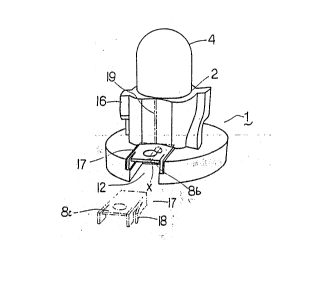
Flg. 9 ~hows a still further embodiment. While ~he
above embodiments ~omprise the contact-strlps which are
formed ~o a~ to clamp an exterior contact board on the top
'
::;
- :
:~ . . .
:
'
'
s~ j s.~ ~ ,
~ u ~
and bottom surfaces, this embodiment comprises: engaging
platforms 16 pro~ectlng from the outer periphery of a
receiving cylinder 2 of a socket body 1; and contact-strips
17 having a cut-and-bent electricity-receivlng portion 8c,
which together clamp an exterior contact board. In this
embodiment, the contact-strips 17 are formed so as to have a
sectional shape like an inverted "U" with sharp corners.
The contact-strips 17 are inserted toward the center of the
socket body 1 in a direction intersecting the direction of
0 insertion of a lamp 4 (in a direction along the flange
bottom surface). The contact strips 17 also have cut-and-
bent stoppers 18 formed at the sides thereof, which engage
with portions of the body when inserted therein, thus
preventing the contact-strips 17 from slipping out.
Further, in the embodiment shown in Fig. 9, slits 19
(shown by two-dot lines in the figure) may be formed by
cutting open the peripheral wall of the receiving cylinder 2
in the direction of the insertion of the lamp 4 toward the
portions where the contact-strips 17 are inserted. With
thi~ construction, lead wires S, 5 of the lamp 4 are bent
apart at the portions close to the lamp base and are
positioned facing the slits 19, and thus the lead wires 5, 5
can be positioned at welding portions of the contact-strips
instantly when the lamp 4 is inserted in the receiving
~25 cylinder 2. In this case, the contact-strips 17, 17 may be
,,.
.
,
' ' ' ' '
-, ' ' - ,' ,, '
-
- - - - - : - .-
i 2 ;~ ~ ~ v ~ ~
inserted in the socket body 1 either before or after the
insertion of the lamp 4. If the the contact-strips 17, 17
are placed before the lamp 4, the lead wires 5, 5, which are
subsequently placed, are positioned on top of the welding
portions of the contact-strips 17, 17. If the the contact-
strips 17, 17 are placed after the lamp 4, the lead wires S,
5, which are previously placed, are positioned on the lower
side, i.e. the reverse side, of the welding portions of the
contact-strips 17, 17.
Fig. 10 shows still another embodiment of an
electrically-conductive metallic contact-strip in a socket
according to the present invention. Contact-strips 17, 17
have electricity-receiving portions 8c which are cut and
bent following the direction of the rotation of the flange
3. The contact-strips 17, 17 are placed in the socket body
1 (see the central longitudinal sectional view shown in Fig.
11) in the following manner. The uncut end of each of the
electricity-receiving portions 8c is ahead ln the direction
in which the flange 3 is rotated when the socket 1 is
~; 20 mounted on an exterior conductive board, and the cut end of
the~elect~icity-receiving portion 8c.is at the other side.
Functional parts which are the same or similar to those
of other~embodiments are denoted by the same numerals.
As~described above, slnce a socket according to the
25 ~present~1nvention employs contact-strips as structural parts
: ~ :~: :
,
.-:
.
: ~ :
. - - . .: :
,
,
: ' ~ :'' ' . ` ' . . ' .' '
~ ~ . . .
in construction of the socket body, elastic force caused by
the material and structure of contact-strips can be
utilized. The elastic force provides contact pressure onto
a conductive board. Despite repetition of the heat cycle
caused by the lamp going on and off, the contact pressure
does not substantially decrease over time. Thus, such a
socket can be used for a long time and can substantially
prevent the lighting failure caused by contact failure
between contact strips and an exterior conductive board.
Particularly since lead wires are rigidly connected to
contact-strips by electric welding, and further, since this
spot welding is performed after the contact-strips are
mounted in the socket body, the forming process for lead
- wires and the positioning operation for the lead wires to
the contact-strips preceding the welding process can be
performed by an automatic processor with the socket body
being held. Thus, all the processes for assembling socket
- bodies, i.e. from inserting contact-strips to fixing lead
wires, can be performed by an automatic machine. As a
result, operation efficiency will be improved.
Also,~ since~;the~lead wires can be positioned along
; welding~portiono;~of contact-strips without being sub~ected
to~ .g.~strong~exterior tension, excessive strain on
eàling~ba?e? of the lead wlres does not occur. In other
25~ word9,;the~causes of cracks or slow-leakage are eliminated.
: ~
,~' ,' ' ' "" ' ' ' , ' ' ' ,' ., ', . , ' ': '
.... .. . . . . . . ......... . .
.. , ~ . , , . ... : . . . . - . .: . - , , . , . :
: : . . - . ' , , '
.
., ... .. , , . 1 9 . ~ n ~ r
u v a
Thus, product quallty can be upgraded.
Further, since a work-space is formed by cutting out a
portion of the socket body, electric welding electro~es can
reach welding portions through the work-space. Thus, means
for welding lead wires after mounting of contact-strips can
be employed.
When the welding portions are formed on protruding ear-
like strips formed at specific sites of contact-strips,
pressingly-contacting electricity receiving portions will
0 not directly receive clamping pressure or impact actlng on
the welding portions during spot welding. Thus, the
electricity receiving portions can be safely maintained in a
predetermined shape for contact with a conductive board.
The same effect can be obtained if the welding portions
are stopper ends of contact-strips. Such contact-strips do
not require portions specifically formed for welding, thus
effectively contributing to the slmplification of the
structure of contact-strips.
Further, if the stopper ends are bent back, after the
spot welding, to obtain the stopping function, the spot
welding can be performed relatively easily. For example,
spot welding electrodes can clamp a stopper end which is not
yet bent but extends downwards. In a case where a priority
is given to the simplification of the contact-strip
structure, the welding portions may not necessarily be
- ,,
.
.
, ',: ' ' "'' , ' .' , ' ' ' '
'
:
- .
:
2~gJ~?~
located at specific sites on the contact-strips but may be,
e.g. on the reverse sides o~ the pressingly-contacting
electricit~ receiving portions.
Still further, since a pair of contact-strips are
mounted onto the socket body in the first process and a lamp
is mounted onto the body in the second process, or since
slits for guiding lead wires are provided on a socket body
into which contact-strips are inserted in a direction
intersecting the direction of the insertion of the lamp, the
process o~ inserting the lamp and the process o~ laying the
lamp lead wires on the contact-strips can be performed in a
continuous operation, smoothly followed by the process of
electrically welding the contact-strips and the lead wires.
Since the process of welding contact-strips and lead
wires i9 per~ormed after mounting them on a socket body,
such a socket structure and manufacturing method thereof can
be achieved.
INDUSTRIAL APPLICABILITY
Thus, a socket with a lamp without a metallic base
according to the present invention can be used as
illuminating devices in automobile guages, or is suitable as
a light source device in a display means comprising, e.g.
many light-source lamps arranged in a grid.
- - . ' .
':
' ' ' .
:, ' . . ' ', , :,