Note: Descriptions are shown in the official language in which they were submitted.
61935_74
2065054
CLEANER UPPER PORTION WITH TOOL STORAGE AND DOOR
BACKGROUND OF THE INVENTION
Field of ths~ Invention
This invention relates to vacuum cleaners and, more
particularly relates to a tool storage and door arrangement
utilized with an upright cleaner.
Summary of t:he Prior Art
The use of internal tool storage with vacuum cleaners
including uP~right: <:leaners has already been developed. However,
the storage arrangement referred to in the first sentence was
designed for use with a hard bag cleaner so that space
constrictions as well as accessibility required it disposition at
or near the top of the hard bag and, thus, medial placement of
the tool storage arrangement which might provide enlarged storage
capability over that described was not contemplated. This
storage posi~ion could, of course, be obtained in a hard bag
cleaner- with some additional dirt capacity penalty but, moreover,
could very advantageously be provided in a cleaner having an
upper portion hard housing not utilized as a hard bag cleaner
upper portion.
The use of a covering door for this storage arrangement
is also apparent :since the the above described tool storage
arrangement also i.nc:ludes as old a variety of closable, swinging
tool doors utilized to cover a variety of tool storage
arrangements. Several of these doors include positive stops and
all inc:Lude non detachable hinges but unless these positive stops
or hinges are structurally very strong there is a possibility of
inadvertent breaking of a hinge or a stop by the operator of the
upright cleaner or even the breaking of the door, itself. Thus a
door, hinge and stop which were not subjected to such undue
operator' strain would also be desirable.
2065054
Accordingly, it is an object of this invention to
provide a tool storage and tool door arrangement medially of
an upright cleaner: upper portion hard housing.
SUMMARY OF THE INVENTION
The invention provides an upright cleaner having a
tool storage arrangement including: a) a hard housing
portion pivoted to a suction nozzle and extending upwardly
therefrom; b) a tool storage well disposed in said hard
housing portion; c) a tool door extending vertically to cover
said tool storage well and hingedly pivoted to said hard
housing portion; dl) said tool door downwardly pivoting for
uncovering said tool storage well to abut an overridable
deformable stop and, upon further forced downward pivoting, to
override said stop and, upon further swinging, to selectively
break-away for release of it from said hard housing portion;
e) said hinged pivoting provided by open, spaced hinge pivot
members forming open slots on one of said door and said
housing; f) hinge: pivot pins on the other of said door and
said housing and disposed in said open slots to permit
pivoting removal c~f said door; g) said overridable deformable
stop mounted on on.e of said tool door and said hard housing
portion removed from and independent of said spaced hinge
pivot members to provide an overridable limit overridden by
said further forced swinging movement of said tool door; h)
said stop, upon being overridden, cammingly permitting said
tool door to pivot further downwardly for its eventual
breakaway release from said hard housing portion; i) said
spaced hinge pivot members having opposed curvilinear open
ends to form a pivot point for hinging of said pivot pins for
- 2 -
61935-74
2065054
swinging of said doors; and j) at least some of said
curvilinear open ends of said spaced hinge pivot members being
acted against by raid pivot pins during breakaway swinging of
said door to cam raid door away from said hinge pivot members
for breakaway final release of said door from said hard
housing portion after said further forced swinging of said
door over said overridable stop.
Thus, tree upright cleaner has a "breakaway" or
detachable feature for the door and its associated structure
l0 so that tool door stop and/or hinge is not easily subject to
breakage by inadvertent overstressing. The cleaner tool door
stop can be overridden by additional forced swinging of the
tool door beyond the normal stop position. In the described
embodiment door i~; easily released from its cleaner.
- 2a -
61935-74
_, Hoover Case 2378
2065054
The door hinge is composed of a pair of spaced horizontally
extending pivot pintles formed integrally with the bottom of the
door which engage in a pair of open clevis portions formed
slightly below the bottom of the tool storage volume in the hard
housing. The tool door pintles lodge in open bores formed in
each of the opening clevis portions at their outer terminations.
i
The remainder of each of the outwardly opening clevis' slots
being narrowed sufficiently to require a slight amount of force i
i
to push the pintles inwardly of the hard housing so that they i
tend to lodge in the bores of the clevis portions. Disposed 1
medially between the clevis portions is mounted, fixed to the
hard housing a cammable stop latch having a downwardly engageable
hook portion which is abuttingly engaged by the tool door at its t
bottom as it swings downwardly open. This latch then provides a
stop for the door to halt its opening movement with the tool door i
substantially ;parallel to the horizontal. However, in the event
that the operator forces the door beyond this point, the bottom
of the door cams the stop downwardly, permitting the door to
"pop" past the stop latch so that it may swing further downwardly ~,
and, essentially, swing out of its clevis mountings to be
.substantially automatically removed from its hinged engagement.
The tool door may be easily remounted by inserting the pintles in
their clevis mountings at a below horizontal angling of the door,
coupled with am upward swinging of the door to engage the bottom
of the door with the nose of the stop latch to cam it again but
this time upwardly to a non interfering position so that the tool
door may be swung past it and closed.
BRIEF DESCRIPTION OF THE DRAWINGS
Reference may be had to the accompanying Drawings for a
better undersitanding of the invention, both as to its
organization and function, with the illustration showing a
preferred embodiment, but being only exemplary, and in which:
3
Hoover Case 2378
2065054
Figure 1 is a left front perspective view of an upright
cleaner incorporating the invention; I
Figure 2 is a front elevational view of the tool door;
I
Figure 3 is a front elevational view of the hard
I
housing portion. and mounted tool door;
Figure 4 is a cross sectional view of the closed tool
door and hard housing as generally viewed when taken generally on
line 4-4 in Figures 2 and 3;
Figure 5 is a similar view with the tool door swung
partly open;
Figure 6 is a detailed view of the tool door hinge
arrangement and cammable stop latch taken generally as indicated
in Figure 4 and showing the tool door closed;
t
Figure 7 is a similar view showing the tool door swung I
to its stop po:;ition prior to caroming override of it;
Figure 8 is a similar view showing tool door swung past
its stop position after caroming the cammable stop latch for
release;
Figure 9 is a similar view but showing the tool door
released from the hard housing upon further swinging movement;
land
Figure 10 is a similar view but showing the tool door
pintles reinserted in their clevises and the tool door caroming
the cammable stop latch during its upward swinging movement.
DETAILED DESCRIPTION OF DRAWINGS
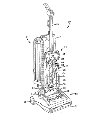
There is shown in Figure 1, an upright cleaner 10
having a mounted hose and tool rack 11 and a floor engaging
nozzle 12 pivoted to a hard housing upper portion 14 surmounted
by a handle 15. A cloth bag 16 which houses the dirt collecting
bag (not shown) is disposed behind the hard housing upper portion
14 to receive the discharge of dirty air from the floor engaging
nozzle 12. A handhold 17 for transportation of the cleaner 10 is
provided in th.e upper reaches of the hard housing upper portion
4
Hoover Case 2378
20fi5054
14. Wheels 18 (only one shown) permit movement of the floor
engaging nozzle 12 over floors to provide for this cleaner's
cleaning function. A manually actuated height elevation knob 19
is movably mounted on the front of the floor engaging nozzle 12
and a furniture guard 21 surrounds this same nozzle.
A tool storage arrangement 20 is disposed in a front 22
of the hard housing and includes a crevice tool 24, a floor
nozzle 26 and a wall and floor brush 28 mounted in a well 30
formed in the hard bag upper portion 14. A tool door 32 covers
the well 30 and may, ideally, be made of smoked transparent
plastic to permit user viewing of the tools from the front of the
upright cleaner.
The tools are conventionally mounted in shaped
depressions in well 30 such as furniture nozzle depression 34 and
wall and floor brush depression 36 (Figures 4 and 5) with the
tools held in these depressions by conventional, spaced plastic
spring fingers (not shown) which compressingly grasp cylindrical
portions of the tools. A wall 38 forming these depressions and
the inward side of well 30 is an integral continuation of front
22 of hard bag upper portion 14.
Tool door 32 includes at its upper end and medially
disposed an integral latch means 40 formed by a pair of integral
latch members 42, 42 each having a catch 44 at its end and a
deformable arm 46 extending to and attached to a back side of
front wall 48 of tool door 32. Each of the opposed latch members
42, 42 then take the general shape of a bottom latch member 50
used as the caammable stop for limiting the tool door 32 swinging
to open position.
The tool door 32 also includes vertical side walls 52,
54 that extend the total height of the front wall 98 of door 32
and a top wall. 56 and bottom wall 58 which .extend along the total
horizontal width of the top and bottom sides of front wall 48.
Hoover Case 2378
2065054
Top wall 56 and front wall 48 are rounded at their juncture as
are the vertical side walls 52 and 54 with their juncture with
I
front wall 48 (not shown) while the bottom wall 58 is chamfered
at its junction with front wall 48. These smooth junctures i
i
provide a pleasing aesthetic effect to the tool door 32. The
front wall 48 may also be slightly bowed from side to side from
I
the top extent of the tool door 32 to its bottom extent to add to
this pleasing effect. Top wall 56 may be made discontinuous at i
its middle to provide an opening 60 in it for a finger hold for
easy operator manipulation of the tool door 32.
The tool door 32 is hingedly attached to the hard I
I
i
housing upper F~ortion 14 near its bottom termination by a pair of
integral pintlea 62, 62 extending parallel to bottom wall 58 but
,set slightly upwardly therefrom, each substantially centered in a
pintle notch 64 extending both through the front wall 48 and
bottom wall 58 so that there is a clearance space in tool door 32
both above and below the pintles 62, 62 for the reception of
their corresponding hinge parts. '
ThesE: pintles are each received in an open clevis
portion 66 (Figures 6-10) formed by two outwardly extending short
arms 68, 70 whiich are turned inwardly towards each other at their
outer ends. This forms a pivot hinge 72 for lodgement of a
pintle 62. By this arrangement, the tool door 32 can be seen as
hingedly swing:lng from the hard housing upper portion 14.
The tool door 32 includes a medially disposed bottom
latching tab or ledge 74 which extends inwardly from and is
aligned with an inner portion 76 of bottom wall 58. This
provides the catch for latch 50 which is integral with an extends
outwardly from hard housing upper portion 14. Latch 50 includes
a nose 78 and a hook 80 to be essentially formed in a
conventional latch shape with the hook 80 situated for engagement
by the latch 74. The latch 50 is plastic and generally
deformable so that it, acting against latching tab or ledge 74,
6
Hoover Case 2378
206505 I
forms a deformable stop for the tool door 32 when swung to its
open position. '
I
This function of tool door 32 is clearly portrayed in
these same Figures 6-10.
In Fj~gure 6 the tool door 32 is shown in closed
position with each of its hinge pintles 62 disposed within its t
pivot hinge 72., The door is latched closed in this position as (
shown, e.g., in Figure 4 covering the tool well 30 and its i
a
mounted tools.
I
In Figure 7, the tool door 32 has hinged
counterclockwise, in the view afforded, from that of Figure 6 as
shown by the long arrow so that the tool door 32 is open for
I
operator selection of a desired tool. To limit this swing, tab I
I
74 on the bottom side 58 of tool door 32 has abutting engaged
latch 50 through its hook 80 to provide a positive stop for the
tool door 32. This may be overcome with additional operator
effort by swinging the tool door 32 further counterclockwise (in
the direction of the long arrow) to cammingly cause the latch 50
I
to rotate cloclkwise in this view (short arrow) to permit the tool
door 32 to swing further downwardly as its tab 74 clears from
latch hook 80.
In Figure 8, the tool door 32 is shown swung past
.engagement of latch 50 with ledge or tab 74 to place these two
elements in a non-abutting, non-interfering relationship while
the pintle 62 of tool door 32 is still engaged with the pivot
hinge.
In Figure 9 the tool door 32 is shown as it has been
swung further downwardly to a completely released position. This
release is occasioned by each of the tool door pintles 62
essentially walking out of the pivot hinges 72 by the pintles
caroming against the inside of the lower arm 70 and forcibly
springing past the upper arm 68. The tool door 32 is then
completely removed from the upright cleaner 10 so that a
7
Hoover Case 2378
2065054
breakaway feature is provided for this door through the
cooperation of the latch 50, pintles 62, 62 and pivot hinges 72,
72.
Figure 10 illustrates the remounting of the tool door
32. It is shown as rotated to be positioned, with the pintles
62, 62 in an inserted position within the hinge pivots 72, 72,
with the tab 7~4 downwardly or outwardly of the latch 50 but
~lengaged with it. This engagement of the latching tab 74 with the
nose 78 of the latch 50 as the tool door 32 swings clockwise
upwardly (long arrow) cams the latch 50 also clockwise (short
arrow) until tlhe tab 74 clears the latch 50 and takes a position
inwardly or belhind it. The latch 50 springly moving back to its
original and undeformed state at this time. This relative
position of tool door 32 and its latch 50 and latching tab 74 can
be seen by again viewing Figure 7. It should now be obvious that
both assembly .and disassembly of the tool door 32 from the hard
housing upper portion 14 is occasioned by upward or downward
swinging of this tool door and a caroming engagement and
disengagement ~~f its latch means 82 formed by latch 50 and latch
tab 74.
It slhould be clear that the structure described fully
meets all the objects set out for it in this Application and,
that, there could be many changes made to it which would still
fall within ita spirit and purview. For example, the releasable
hinges of this structure could be utilized alone but there would
be a tendency for the tool door to collide with the hood before
separation of the tool door occurred. Also, the cammable stop of
this structure could be utilized with non releasable hinges and
it would still serve somewhat as a stress protector for the tool
door and its hinges and stop.
8