Language selection

Search

Patent 2065169 Summary

Third-party information liability

Some of the information on this Web page has been provided by external sources. The Government of Canada is not responsible for the accuracy, reliability or currency of the information supplied by external sources. Users wishing to rely upon this information should consult directly with the source of the information. Content provided by external sources is not subject to official languages, privacy and accessibility requirements.

Claims and Abstract availability

Any discrepancies in the text and image of the Claims and Abstract are due to differing posting times. Text of the Claims and Abstract are posted:

  • At the time the application is open to public inspection;
  • At the time of issue of the patent (grant).
(12) Patent Application: (11) CA 2065169
(54) English Title: RETAINER RING
(54) French Title: BAGUE DE RETENUE
Status: Dead
Bibliographic Data
(51) International Patent Classification (IPC):
  • E21B 33/03 (2006.01)
  • E21B 17/10 (2006.01)
  • E21B 23/02 (2006.01)
  • F16B 21/18 (2006.01)
  • F16L 37/088 (2006.01)
(72) Inventors :
  • THORNBURROW, EDWARD T. (United Kingdom)
(73) Owners :
  • COOPER INDUSTRIES, INC. (United States of America)
(71) Applicants :
(74) Agent: DEETH WILLIAMS WALL LLP
(74) Associate agent:
(45) Issued:
(22) Filed Date: 1992-04-06
(41) Open to Public Inspection: 1992-10-10
Availability of licence: N/A
(25) Language of filing: English

Patent Cooperation Treaty (PCT): No

(30) Application Priority Data:
Application No. Country/Territory Date
91303096.1 European Patent Office (EPO) 1991-04-09

Abstracts

English Abstract


ABSTRACT


A retainer ring for retaining generally
tubular member (10) within a generally cylindrical
bore (11). The ring comprises a split-ring like
member 16 which has a radially extending portion or
portions which define a shoulder 26 for engaging a
groove 18 in the wall of the bore 11. The ring is of
non-uniform diameter such that it exhibits a generally
wave-like form in its circumferential direction. The
retainer ring has application to retaining a wear
bushing in a wellhead system.


Claims

Note: Claims are shown in the official language in which they were submitted.


THE EMBODIMENTS OF THE INVENTION IN WHICH AN EXCLUSIVE
PROPERTY OR PRIVILEGE IS CLAIMED ARE DEFINED AS FOLLOWS:

1. A retainer ring for use in retaining a
generally tubular member within a generally
cylindrical bore comprising a split-ring like member
having a radially extending portion or portions which
define a shoulder for engaging a groove in the wall of
the bore, the ring being of non-uniform diameter such
that it exhibits a generally wave-like form in the
circumferential direction of the ring.

2. A retainer ring according to claim 1,
wherein the waveform is of very shallow amplitude and
is generally sinusoidal.

3. A retainer ring according to claim 1 or
claim 2, wherein the peaks of the waveform are
distributed equi-angularly around the ring.

4. A retainer ring according to any preceding
claim, wherein the outer periphery of the ring defines
a shoulder inclined at approximately 45° to the
ring axis.

5. A retainer ring according to claim 4,
wherein the outer periphery of the ring also defines a
shallow taper extending from an end face of the ring
to assist insertion of the ring into the cylindrical
bore.

6. A wear bushing including a retainer ring
according to any preceding claim disposed in a
circumferential groove in the bushing.

Description

Note: Descriptions are shown in the official language in which they were submitted.


--~ 2 ~


RETAINER RING

This invention relates to a retainer ring
for use in retaining a generally tubular member within
~ g~nerally cylindrical bore. The retainer ring has
par~icular application to the retention of a wear
bushing within a wellhead system, although its use is
by no mean~ limited to such an application.

During drilling operations which occur in
the formation of well bores it i5 the practice to
insert wear bushings within the wellhead system in
order to protect the bore of the wellhead system from
damage during such operation~. The walls of the bore
in the wellhead system typically have one or more
circumferen~ial grooves which are used to support
equipment in the well bore. Wear bushings
conventionally employ re~ainer ring~ which engage such
grooves to retain the wear bushing within the bore. A
common type of retaining ring used in the retention of
wear bushings is an elastomer ring. Such rings are
employed since quite commonly wi~h wall thicknesses of
the order of ~ inch it is not possib}ç to use
latches or other mechanical devices in the limited
sp~ce available. However, elastomer rings have no~
proved tD be entirely satisfactory 6ince the reten~ion
force which they can generate is l~mited. The presen~
invention i~ concerned with an Lmproved form of
retaining ring which can be used in retain~n~ a
~ubular member within a bore where the space for the
retention ring is relatively restricted.


According to the present invention there is
provided a xetainer ring for use in retaining a
generally tubular member within a generally
cylindrical bore comprising a split-ring like member
having a radially extending portion or portions which
define a shoulder for engaging a groove in the wall of
the bore, the ring being of non-uniform diameter such
that it exhibits a wave-like form in the
circumferential direction of the ri~g.

The waveform may be of very ~hallow
amplitute and be generally ~inusoidal. The peaks of
the waveform may be distributed equi-angularly around
the ring. The ring, for example, may include eight
lobes uniformly distributed around the ring.

The outer periphery of the ring may define a
shoulder inclined at approxlmately 45 to the ring
axi~. The outer periphery of the ring may also define
a shallow taper extending from an end face of the ring
to assist insertion of the ring into the cylindrical
zo bore.
The retainer ring m y be for retaining a
wear bushing in a wellhead system.

It has been found that the wave-like form of
the present ring is capable o~ producing a ~ignifiGant
retaining forGe when the ring engages the gro~ve in
the wall of the cylindrical ~ore.

The invention will ~e ~escribPd now by way
of example onlyt with particular reference to the
accompanying drawings. In the drawings:
.

~6~;L59


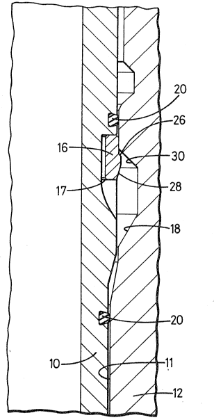
Figure 1 is a sectional view showing a wear
bushing located within ~he cylindrical bore of a
wellhead system;

Figure 2 is a p}an view of a retaining ring
in accordance with the present invention, and

Figure 3 is a section on the line III-III of
Figure 2.

Referr~ng to Figure 1 there is shown a
generally tubular wear bushing 10 which is disposed
within ~he generally cylindrical bore 11 of a wellhead
system 12. The wear bushing as will be apparent to
those skilled in the art is loc~ted in the bore of the
wellhead ~ystem in order to protect the wall of that
bore during the passage of, for example, drilling
equipment into the well bore.

The wear bushing 10 is retained in the bore
by means of a retainer ring 16 which is di~po~ed
~thin a circumferential grooYe 17 ~ormed in outer
wall of the wear bushing. The ret~iner ring 16
eng~ge~ a groove 18 in the wall of the cylin~rical
bore to retain the wesr bushing within the bore.
Seals 20 are provided on opposite side~ of the
re~ainer ring and provide a seal be~een the bushing
And the wall of the bore 11.

Referring to Figure 2 of the drawing~, ~he
retainer ring i~ of the split ring type. ~he ring is
split at 22, the gap ~etween the ends being typically
~ inch. As shown in Figure 2 of the drawings the
retainer ring is of non-uniform diameter and exhibits
a wave-like form in the circumferential direc~ion of


. . .

2 ~ ~`g ~

- 4 -
the ring. This waveform is very shallow and generally
~inusoidal. The high points are being indicated at H
and the low points at L. It has been found that this
configuration substantially increases the retentlon
force which can be provid2d by ~he retaining ring. In
the form of the ring shown in Figure 2 there are eight
wavelengths distributed equiangularly around the
circumference of the ring so that typically there is
an angular spacing o 45 between successi~e high
point~ H on the ring. It will be appreciated with
refer~nce to Figure 1 of the drawing~ that it i8
princ~pally in the region of the high point~ that
engagement occurs between the xing and the groove in
the bore wall. ~he ~ection of Figure 1 is t~ken
through a high point on the ring.

Referring now to Figure 3 it will be seen
that the outer surface of the ring is formed w~th a
radia~ly pro~ecting part which defines a shoulder 26
which extends at approximately 45 to the axis of
the ring~ The pro~ecting part also define~ a ~hallow
tapering surface 28 which extends at approximately
15 to the axi~ of tha ring.

The material from which the ring i5
construc~ed i~ not critical and t~pically c~n be a low
all~y ste21.

To install the wear bushing in ~he wellhe~d
bore the retainer ring is initially located in ~he
groo~e 17 formed in the outer periphery of th~ wear
bushing, The wear bushing is then in3erted i~to ~h~
cylindrical bore and movement of th~ ret~ining ring
into the bore is assisted by the shallow taper 28
formed on the outer periphery of the ring. Nhen the

,.. ~ 2 ~


retainer ring reaches the axial location of the groove
lB formed in the wall of the cylindrical bore 11 it
springs outwardly so that the shoulder 26 can enga~e
the inclined wall 30 of the groo~e 18 ~nd hence resist
removal of the wear bushing from the wellhead. It
will be appreciated that it is principally at the high
points around the circumference of the ring tha~
engagement occurs ~etween the shoulder 26 and the wall
of the groove 18.

The wear bushing can be removed by
application of significant upward force to the wear
bushing using suitable equipment located at, for
example, a drilling platform. It hac been found that
the pre~ent ring can be retrieved from a wear bu~hing
and used many times over without any significAnt wear
occurring to the ring.

It will he appreciated that whilst the
retainer ring has been de~cribed specifically in
relation to the retention of a wear bushing within a
well bore the ring has much wider application
generally to the retention of a tubul~r member within
a generally cylindrical bore.

Representative Drawing
A single figure which represents the drawing illustrating the invention.
Administrative Status

For a clearer understanding of the status of the application/patent presented on this page, the site Disclaimer , as well as the definitions for Patent , Administrative Status , Maintenance Fee  and Payment History  should be consulted.

Administrative Status

Title Date
Forecasted Issue Date Unavailable
(22) Filed 1992-04-06
(41) Open to Public Inspection 1992-10-10
Dead Application 1995-10-08

Abandonment History

There is no abandonment history.

Payment History

Fee Type Anniversary Year Due Date Amount Paid Paid Date
Application Fee $0.00 1992-04-06
Registration of a document - section 124 $0.00 1993-06-25
Maintenance Fee - Application - New Act 2 1994-04-06 $100.00 1994-03-31
Owners on Record

Note: Records showing the ownership history in alphabetical order.

Current Owners on Record
COOPER INDUSTRIES, INC.
Past Owners on Record
THORNBURROW, EDWARD T.
Past Owners that do not appear in the "Owners on Record" listing will appear in other documentation within the application.
Documents

To view selected files, please enter reCAPTCHA code :


To view images, click a link in the Document Description column. To download the documents, select one or more checkboxes in the first column and then click the "Download Selected in PDF format (Zip Archive)" or the "Download Selected as Single PDF" button.

List of published and non-published patent-specific documents on the CPD .

If you have any difficulty accessing content, you can call the Client Service Centre at 1-866-997-1936 or send them an e-mail at CIPO Client Service Centre.


Document
Description 
Date
(yyyy-mm-dd) 
Number of pages   Size of Image (KB) 
Office Letter 1994-05-31 1 20
Office Letter 1992-10-23 1 33
Description 1992-10-10 5 186
Drawings 1992-10-10 2 40
Claims 1992-10-10 1 36
Abstract 1992-10-10 1 15
Cover Page 1992-10-10 1 14
Representative Drawing 1999-07-06 1 18
Fees 1994-03-31 1 37